Fluke 3563 User manual

Fluke 3563 Sensor/Gateway Installation
Quick Guide and Checklist

2 Fluke Corporation Fluke 3563 Sensor/ Gateway - Installation
Unpack the
product
Step-1
Create an account
Step-2
Set up groups,
assets, and test
points
Step-3
Commission
gateways, then
sensors
Step-4
Position/install
sensors and
gateways
Step-5
Evaluate readings
Step-6
Step 1: Unpack the product
Step 2: Create an account
Step 3: Set up groups, assets, and test points
Step 4: Commission gateways, then sensors
Step 5: Position/install sensors and gateways
Step 6: Evaluate readings
Steps to follow:
Fluke 3563 Sensor/Gateway Installation
Quick Guide and Checklist

3 Fluke Corporation Fluke 3563 Sensor/ Gateway - Installation
STOP
Description 16KIT Quantity
3503 Gateways 2
3563 Analysis Vibration Sensors 16
Software subscriptions enabled for sensors 16
Getting Started Manual 1
Carefully unpack all items from the box. See below:
Unpack the ProductStep 1
Watch the setup video to see the system setup and installation:
http://www.fluke.com/quickstart
Important: For a successful setup, follow the sequence in these instructions.
Do not permanently install sensors/gateways until the very end of Step 5.
Before you install:
Required Accessories: Mounting Plate (Screw or Adhesive) and
Adapter key — adhesive mount included; screw mount optional
3563 Analysis Vibration Sensors (16)
3503 Wireless Gateways (2)

4 Fluke Corporation Fluke 3563 Sensor/ Gateway - Installation
Call: 425-200-0080 for more information.
Create a new login account
1. Access the LIVE-Asset™ web page by going to
live-asset.com or scanning the QR code to the right.
2. Click “Sign up,” and then enter your email address in the
provided field on the new page.
3. Click “Register” to proceed. A hint appears on the page
indicating that a verification email has been sent to the
provided email account.
4. Upon receiving the verification email, follow the link.
5. From the Accelix page, enter information as required.
6. After successfully creating the user account, click Go to
Login Page to navigate to the application’s login page.
After starting the application, define the required test points for specified assets.
To define the test points:
Setup groups, assets, test points
y Create Location (e.g., company; location of plant; site or facility)
y Create Sublocation (if required)
y Create Asset (machinery)
y Enter Asset Details
y Define Components
y Define Test Points (bearing location)
y Define Tasks and Alarms
y Define Device Settings
Step 3
Step 2
1. To set up the asset from the application,
The configuration icon is the module where assets
are set up. Detailed information about configuration
is in LIVE-Asset™ Portal online help.
yClick the Configuration icon ( ) to access the
Configuration module.
yClick ? ( ) at any time to access the online help.
yClick the Edit tab ( ) to create an Asset hierarchy.
y
1
2
3
Scan QR code to go to:
www.live-asset.com
1
2
3

5 Fluke Corporation Fluke 3563 Sensor/ Gateway - Installation
Detailed information about the different trend measurements
is available at the software online help, which is accessed by
clicking ?on the header.
2. Click Add Group and edit the location name. If required, click
Add SubGroup and edit the name of the sublocation. See at
left.
3. Click Add Asset. The Asset name may be edited only in the
Asset Details editor, where other asset properties, including
speed, power, ID, and type of foundation, may also be edited.
See at left.
4. Use the Components editor to define the asset components.
See at left.
5. In the Test Points editor, click the Add test point tab at the
respective components, and then use the drop-down menus
to define the required test points:
yTest point name – edit name
yPosition on the machine – define test point position
yOrientation – define sensor orientation at the test point
6. Use the Tasks & Alarms editor to configure the vibration
trends to be measured and the alarm limits to be set. You can
choose to apply recommended alarm limits that are based on
verified ISO standards and experience.
7. Use the Device Settings editor to set the interval of the mea-
surement cycles (Overall Measurement interval) and data
transfer cycles (Overall Reporting interval). For detailed infor-
mation, refer to the LIVE-Asset™ Portal online help.

6 Fluke Corporation Fluke 3563 Sensor/ Gateway - Installation
STOP
The Fluke Connect app supports the commissioning process. The app may be downloaded
from the App Store (for iOS) or Google Play (for Android).
Important: Complete all steps in this section
before you mount the gateway or the sensors.
1Ethernet (PoE) communication port
224 V DC input terminal
Download Fluke Connect
1. Go to the appropriate download platform and
download the Fluke Connect app.
2. Install the app on a mobile device.
3. Launch the app and log in.
yLog in using the email address and password
registered in LIVE-Asset™ Portal.
Commissioning gateways. Then sensors
Add gateway
1. Power the gateway using either Power over Ethernet
(PoE) or the supplied 24 V DC adapter. The power on
LED lights up.
Note: The Login screen may be used to request login
credentials by tapping Forgot password?
Note: Do the commissioning process at a location with a verified internet connection.
Step 4
2. From the commissioning Home screen, tap Add New to
start the gateway commissioning process.
Note: The user can only commission sensors only after one
gateway is commissioned.
3. In the Setup Overview screen that appears, tap Start
Setup. The Add New Gateway screen opens with the
options to scan the gateway QR code or connect the
gateway manually.
Note: If the manual connection is selected, the
gateway information fields must be entered manually.
This information is on the gateway housing.

7 Fluke Corporation Fluke 3563 Sensor/ Gateway - Installation
NOTE: If the connection between Fluke
Connect and the gateway fails, a hint to
retry the process appears. Try to rescan the
QR code. If gateway details were entered
manually, retry scanning the QR code.
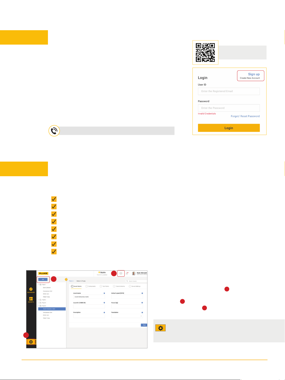
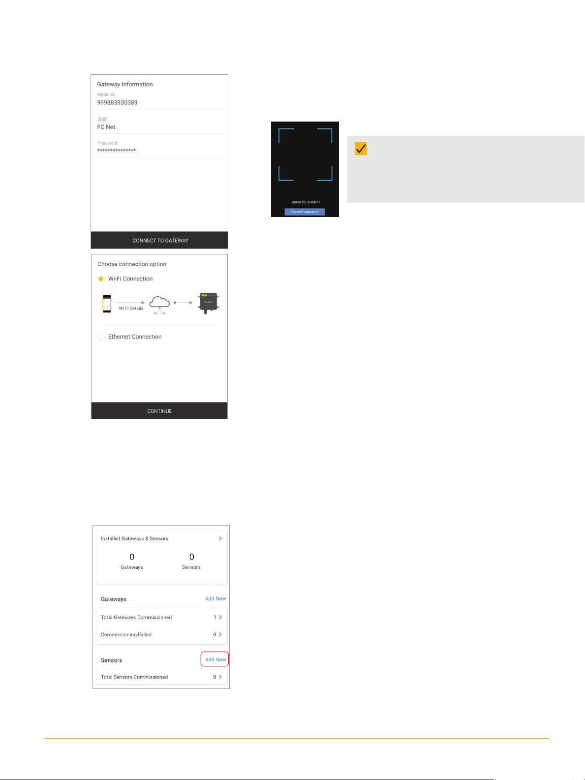
4. Tap Connect To Gateway to establish communication between
the Fluke Connect app and the gateway. A connection is estab-
lished between the gateway and the Data Platform.
5. The gateway connects to the Data Platform using either a Wi-Fi
or Ethernet connection. The Configure Network Details screen
offers the options.
6. If using Wi-Fi, select Wi-Fi Connection and tap Continue. If using
an Ethernet connection, connect the gateway Ethernet port to
the network using an Ethernet cable and tap Continue. Use any
saved network or detected network or add a network.
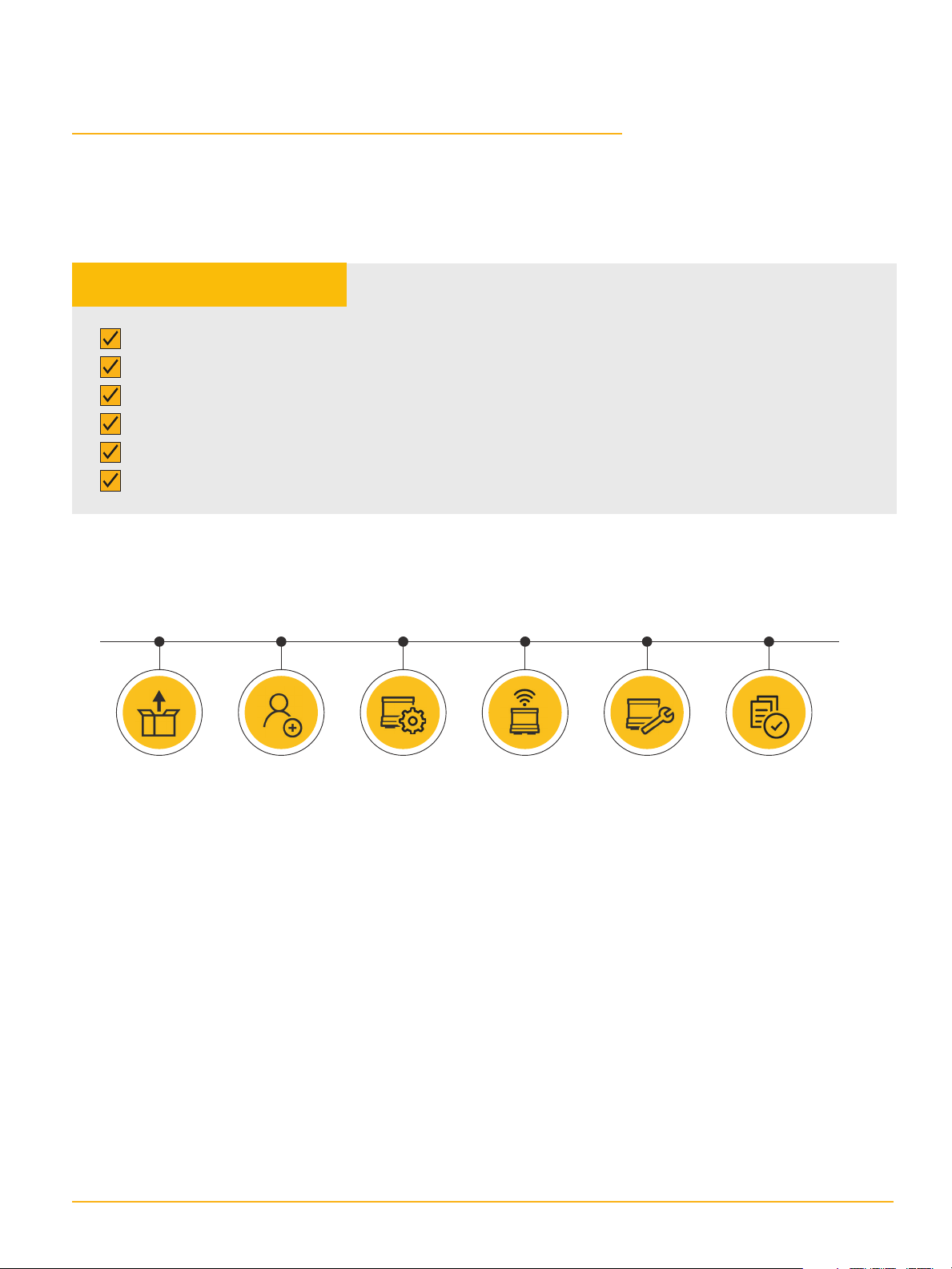
Commissioning sensors
With at least one gateway commissioned, the user may now commission sensors. Make sure the
sensors are correctly powered. If battery terminals were protected during transport, ensure that the
insulation is removed.
yDetected network: Provide the network credentials, and then
tap Update To Gateway to send information to the gateway.
yAdd a network: Enter the necessary network details such as
SSID (network name), type of security required, and the pass-
word. Check the relevant box to save the network to the Fluke
account.
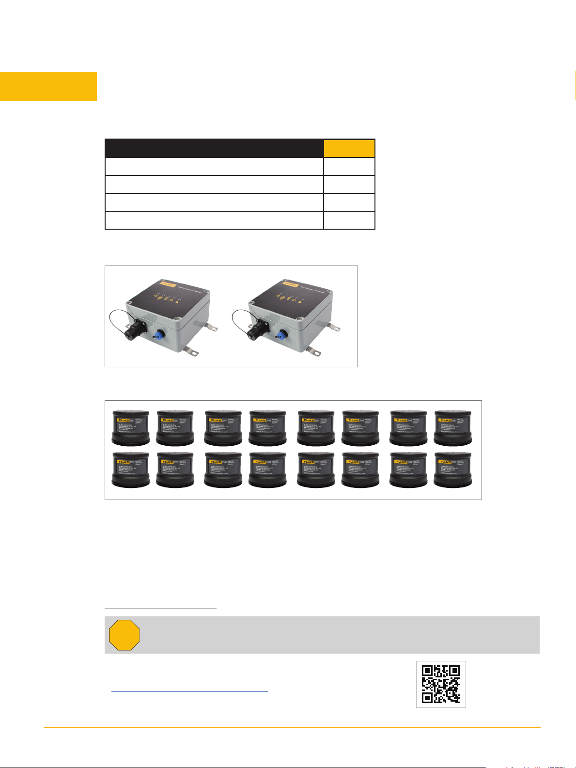
1. From the Home screen, tap Add New in the Sensors. Use
one of these methods:
yAutomatically — Tap the Auto Detect On/Off button to find sen-
sors automatically. All detected sensors will appear on the Sen-
sors screen. (They must be in the vicinity of a powered gateway,
which must be commissioned and connected to the Data Plat-
form.)
yManually — Tap Manually to proceed to Add Manually screen.
Tap Add and then enter the sensor serial number in the Serial
No. field. When all sensors have been entered, Tap Save. The
sensors will appear.
yQR Code — Tap the QR code icon and scan the QR code affixed to
the side of the sensor. Once scanned, the sensor is listed on the
Sensors screen.
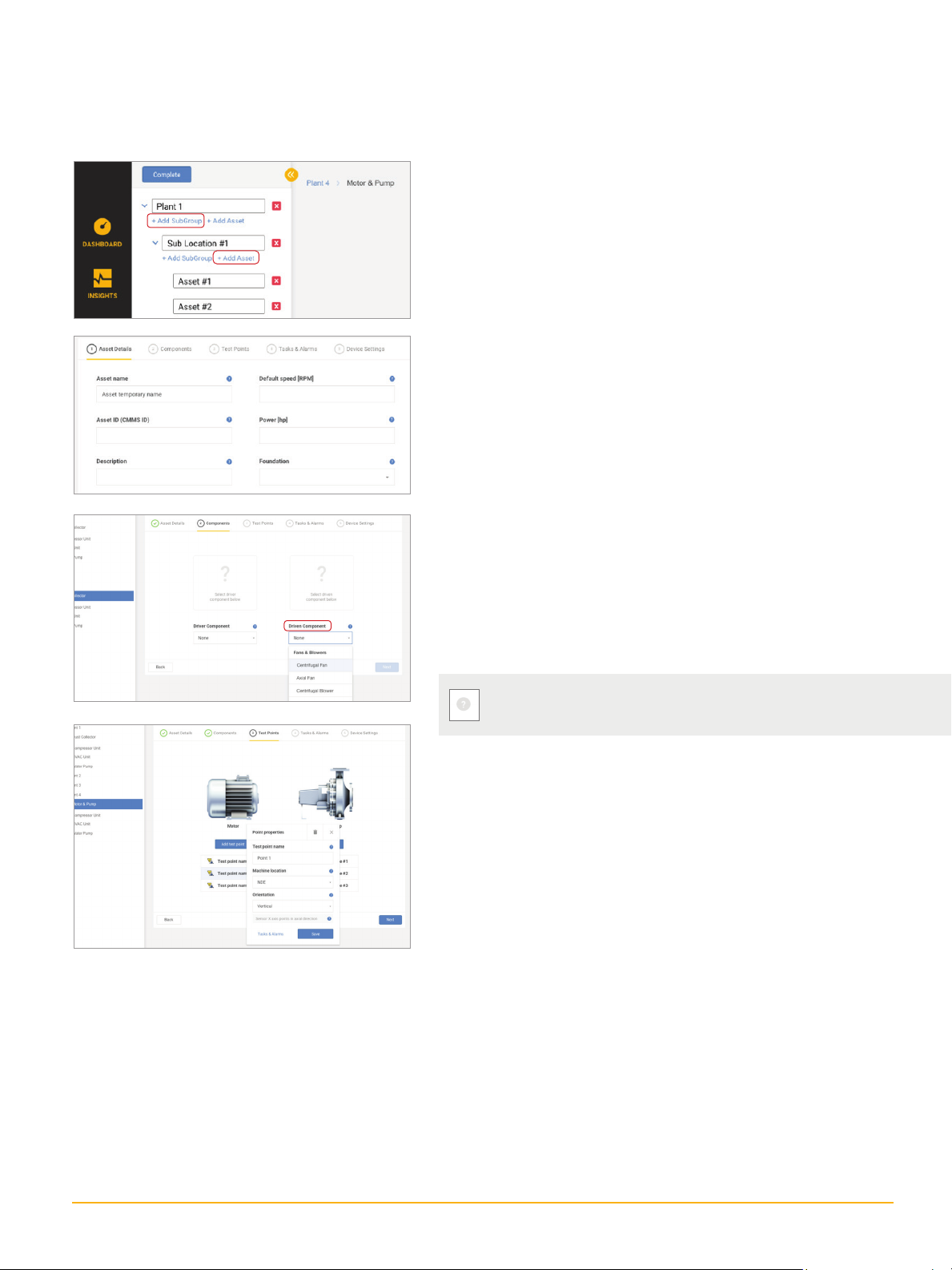
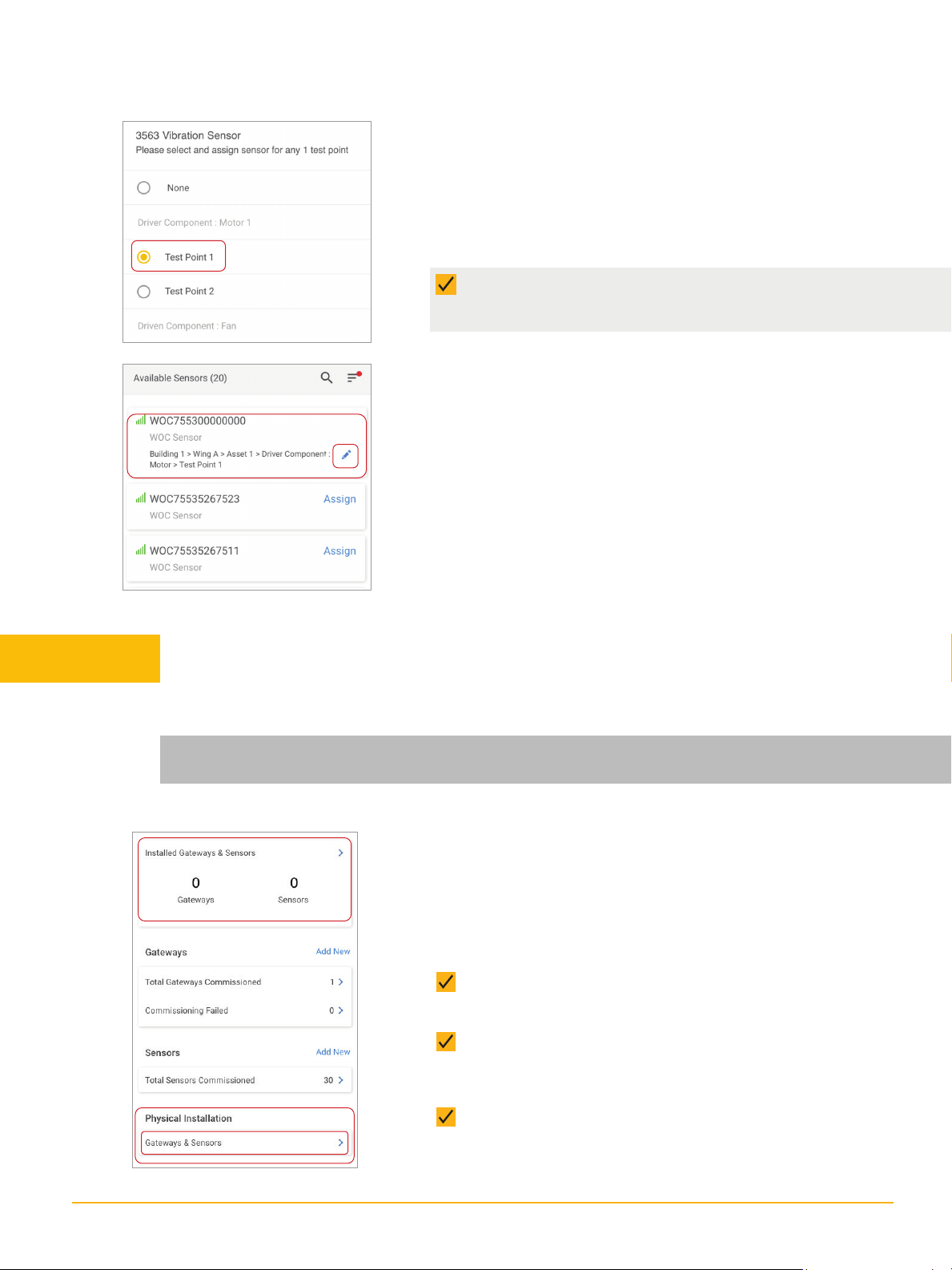
2. Tap Assign at the respective sensor to assign the sensor to a
specific test point on an asset. Or tap Done to exit the screen
and return to the Home screen.

8 Fluke Corporation Fluke 3563 Sensor/ Gateway - Installation
1. Tap Assign on the Sensors screen. The asset hierarchy in the
Web-based software appears.
2. Assign the selected sensor to the desired asset test point.
3. Tap Save to complete the action.
Assign sensors to asset test points
yOn completion, the assigned sensor appears on the sen-
sor list with a breadcrumb showing the test point within
the hierarchy (e.g., Building 1>Wing A>Asset1>Driver
Component>Motor>Test Point1).
yTo change or unassign a test point, tap the pencil icon (next
to the breadcrumb). This returns the user to the individual
asset screen.
NOTE: If no asset hierarchy has been configured within the
LIVE-Asset™ Portal, no asset hierarchy will appear when Assign
is selected
Select gateway to install
1. From the Home screen, tap Gateways & Sensors in the Physical
Installation frame to select the gateway to be installed. All com-
missioned gateways appear under Available Gateways.
2. The following actions are available:
ySelect an active gateway, tap Continue, and position at the
desired location.
ySelect an inactive gateway, tap Connect to be guided
through the process of connecting the gateway to the cloud-
based Data Platform.
yTap Skip to bypass the gateway installation and proceed
directly with sensor installation.
This section guides the user to physically mount gateways and sensors and should be
performed on-site.
Step 5 Position/install sensors and gateway
Important: Temporarily position sensors and gateways as you complete all steps in this section
before you permanently mount the sensors or gateways. They may need to be repositioned.

9 Fluke Corporation Fluke 3563 Sensor/ Gateway - Installation
Select sensor to install
1. All commissioned sensors appear in the Select Sensor to Install
screen. Select sensors to be installed, then tap Continue and
position the sensors at the designated test points.
Check gateway and sensor connection
1. From the Instructions screen that appears, tap
Continue to check whether the sensors are connected to the
gateway.
yOn-screen hints show if connectivity between the gateway
and any sensor fails. If necessary, reposition the gateway.
yAn additional gateway may be selected for installation by
tapping Add Gateways.
yThe sensor connection check is not finalized until all
connection failures are resolved. Sensors that fail to connect
to the gateway must be removed.
Mount sensor permanently and finish Fluke Connect process
1. AFTER connectivity with all sensors has been achieved, tap Continue and mount the sensors
permanently at the selected asset test points, as described in the mounting instructions.
2. AFTER mounting the sensors permanently, return to the Fluke Connect App to finalize the
permanent installation process.

10 Fluke Corporation Fluke 3563 Sensor/ Gateway - Installation
Mount gateways permanently and
finish with Fluke Connect
1. AFTER confirming connectivity with all sensors,
mount the gateways permanently at the deter-
mined position as described in the Mounting
instructions.
2. AFTER mounting the gateway(s) permanently,
return to the Fluke Connect app to finalize the
permanent installation process. Check the
Installed box, then tap Done. Check the number
of gateways and sensors installed.
You are now ready to remotely view vibration trends, alerts, and alarms from your sensors.
Step 6 Evaluate readings remotely
Fluke Corporation
PO Box 9090, Everett, WA 98206 U.S.A.
Fluke Europe B.V.
PO Box 1186, 5602 BD
Eindhoven, The Netherlands
For more information call:
In the U.S.A. 856-810-2700
In Europe +353 507 9741
In UK +44 117 205 0408
Web access: http://www.accelix.com
©2021 Fluke Corporation. Specifications subject to
change without notice. 6/2021 6013901b-en
Modification of this document is not permitted
without written permission from Fluke Corporation.
Table of contents
Other Fluke Accessories manuals

Fluke
Fluke 700P01Ex User manual

Fluke
Fluke 80K-15 User manual

Fluke
Fluke 700P29 User manual

Fluke
Fluke RUBBER SHOE ACCESSORY PN 3125710 User manual

Fluke
Fluke 700P00 Service manual

Fluke
Fluke PPC4 User manual

Fluke
Fluke 9040 User manual

Fluke
Fluke 80PK-3A User manual

Fluke
Fluke 80i-110s User manual

Fluke
Fluke 3562 User manual

Fluke
Fluke 805ES User manual

Fluke
Fluke VIBCODE VIB 8.660 User manual

Fluke
Fluke 80PK-IR User manual

Fluke
Fluke Thermalert 4.0 User manual

Fluke
Fluke 9135 User manual

Fluke
Fluke FLK-050-CLKT Instruction manual

Fluke
Fluke U1500s User manual

Fluke
Fluke Thermalert 4.0 Series User manual

Fluke
Fluke VIB 6.631 Owner's manual

Fluke
Fluke 80T-150UA User manual