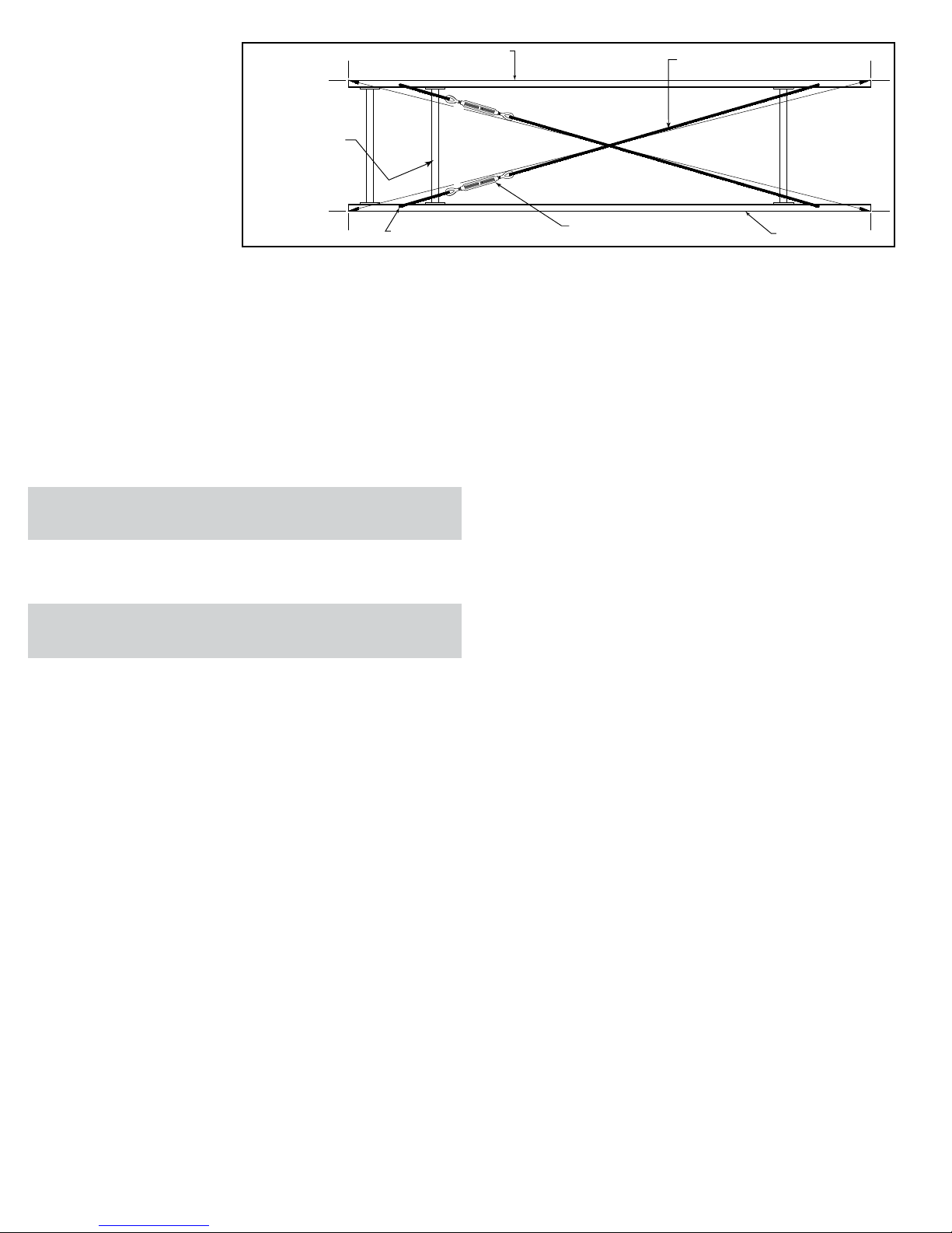
• Racked Sections
It is important that each bed section
be checked for a “racked” or out-
of-square condition. If conveyor is
not square, tracking problems will
result. Figure 6A indicates a racked
section.
TO CORRECT AN OUT-OF-
SQUARE SECTION
1. Locate points on corners of sec-
tion and measure distance “A” &
“B”. If the dimensions are not equal,
the section will need to be squared.
(Figure 6A).
2. Use crossbracing supplied on
underside of conveyor to square
each section. Adjust turnbuckle until Dimensions “A” & “B” are equal.
3. After all bed sections have been checked and corrected for “racked condi-
tion”, tighten all butt couplings and pivot plate bolts.
4. Make final check to see that all conveyor sections are level across width
and length. If entire conveyor is level, supports can be lagged to floor.
OPERATION
• Conveyor Start-Up
Before conveyor is turned on, check for foreign objects that may have been
left inside conveyor during installation. These objects could cause serious
damage during start-up. After conveyor has been turned on and is operat-
ing, check motors, reducers, and moving parts to make sure they are work-
ing freely.
MAINTENANCE
• Electrical Equipment
CONTROLS
Electrical Code: All motor controls and wiring shall conform to the National
Electrical Code (Article 670 or other applicable articles) as published by
the National Fire Protection Association and as approved by the American
Standards Institute, Inc.
CONTROL STATIONS
A) Control stations should be so arranged and located that the operation of
the equipment is visible from them, and shall be clearly marked or labeled to
indicate the function controlled.
B) A conveyor which would cause injury when started shall not be started
until employees in the area are alerted by a signal or by a designated person
that the conveyor is about to start.
When a conveyor would cause injury when started and is automatically
controlled or must be controlled from a remote location, an audible device
shall be provided which can be clearly heard at all points along the conveyor
where personnel may be present. The warning device shall be actuated by
the controller device starting the conveyor and shall continue for a required
period of time before the conveyor starts. A flashing light or similar visual
warning may be used in conjunction with or in place of the audible device if
more effective in particular circumstances.
Where system function would be seriously hindered or adversely affected
by the required time delay or where the intent of the warning may be misinter-
preted (i.e., a work area with many different conveyors and allied devices),
clear, concise, and legible warning shall be provided. The warning shall
indicate that conveyors and allied equipment may be started at any time, that
danger exists, and that personnel must keep clear. The warnings shall be
provided along the conveyor at areas not guarded by position or location.
C) Remotely and automatically controlled conveyors, and conveyors where
operator stations are not manned or are beyond voice and visual contact from
drive areas, loading areas, transfer points, and other potentially hazardous
locations on the conveyor path not guarded by location, position, or guards,
shall be furnished with emergency stop buttons, pull cords, limit switches, or
similar emergency stop devices.
All such emergency stop devices shall be easily identifiable in the imme-
diate vicinity of such locations unless guarded by location, position, or guards.
Where the design, function, and operation of such conveyor clearly is not
hazardous to personnel, an emergency stop device is not required.
The emergency stop device shall act directly on the control of the con-
veyor concerned and shall not depend on the stopping of any other equip-
ment. The emergency stop devices shall be installed so that they cannot be
overridden from other locations.
D) Inactive and unused actuators, controllers, and wiring should be removed
from control stations and panel boards, together with obsolete diagrams, indi-
cators, control labels, and other material which serve to confuse the opera-
tor.
SAFETY DEVICES
A) All safety devices, including wiring of electrical safety devices, shall be
arranged to operate in a “Fail-Safe” manner, that is, if power failure or failure
of the device itself would occur, a hazardous condition must not result.
B) Emergency Stops and Restarts. Conveyor controls shall be so arranged
that, in case of emergency stop, manual reset or start at the location where
the emergency stop was initiated, shall be required of the conveyor(s) and
associated equipment to resume operation.
C) Before restarting a conveyor which has been stopped because of an
emergency, an inspection of the conveyor shall be made and the cause of
the stoppage determined. The starting device shall be locked out before any
attempt is made to remove the cause of stoppage, unless operation is neces-
sary to determine the cause or to safely remove the stoppage.
Refer to ANSI Z244.1-1982, American National Standard for Personnel
Protection – Lockout/Tagout of Energy Sources – Minimum Safety
Requirements and OSHA Standard Number 29 CFR 1910.147 “The Control
of Hazardous Energy (Lockout/Tagout).”
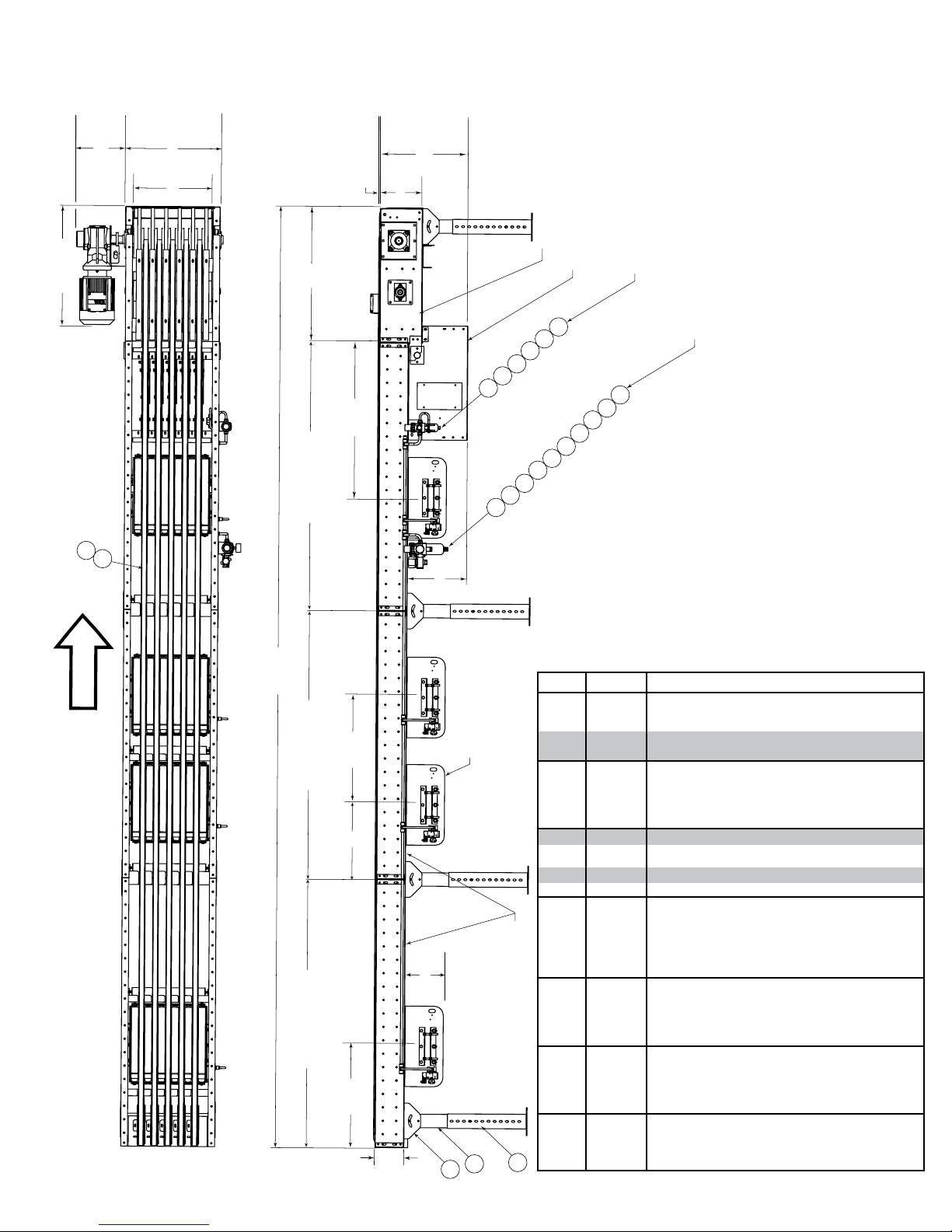
• HyPower Cabling Installation
WARNING: Do not disconnect or connect any HyPower Cabling
Components while under power!
1. All cabling connections are to be made without power on the system.
2. Connect three-phase electrical service to disconnect box. A single-sided
disconnect requires a 15 Amp service, double-sided disconnect requires a 30
Amp service. (See Fig. 7A & 7B)
3. From the disconnect box connect the HyPower Extension Cable(s) to the
HyPower T-Connector.
4. Connect the HyPower T-Connector to the Male HyPower Cable that is
pre-wired to the VFD.
5. Connect the Female HyPower Cable on the VFD to the Male HyPower
Cable pre-wired to the divert motor.
6. Connect the remaining Female connection on the T-Connector to the next
divert zone on the conveyor and repeat steps 3 & 4 for each divert location.
WARNING! Electrical controls shall be installed and wired by a qualified
electrician. Wiring information for the motor and controls are furnished by
the equipment manufacturer.
IMPORTANT NOTE:
Electrical Code: All motor controls and wiring shall conform to the National
Electrical Code (Article 670 or other applicable articles) as published by the
National Fire Protection Association and as approved by the American Standards
Institute, Inc. Subject to local code and local customer acceptance.
FIGURE 6A
(CANAL LATERAL)
SIDE CHANNEL CROSSBRACING (LONG ROD)
FRAME SPACER
CROSSBRACING (SHORT ROD) TURNBUCKLE SIDE CHANNEL
(CANAL LATERAL)
(ESPACIADOR DE CAMA)
(TIRANTE TENSOR [VARILLA CORTA]) (TENSOR)
(TIRANTE TENSOR [VARILLA LARGA])
CAUTION!
Because of the many moving parts on the conveyor, all personnel in the area
of the conveyor need to be warned that the conveyor is about to be started.
6