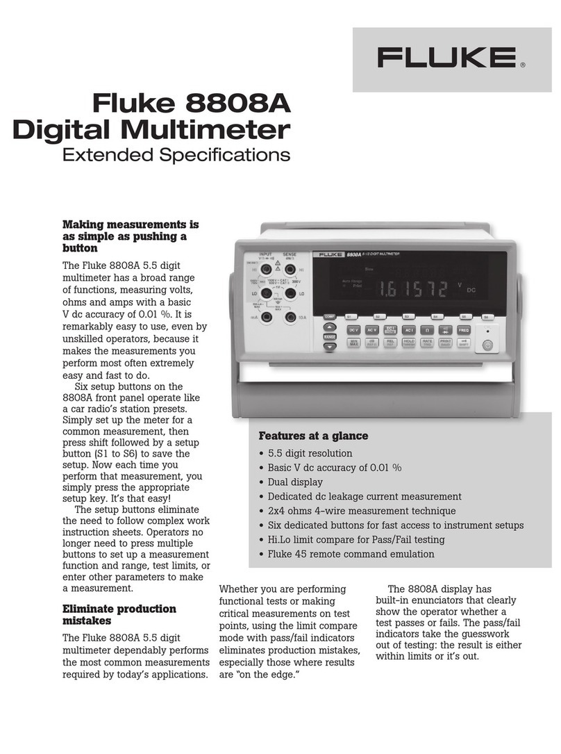
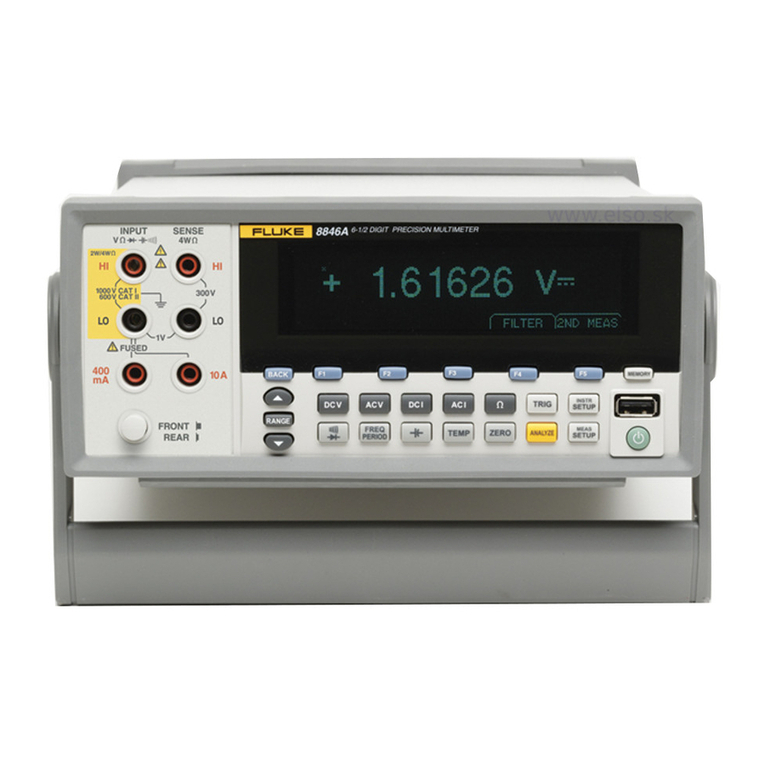
Fluke 183 User manual

®
183 & 185
True RMS Multimeters
Users Manual
February 2001 Rev.2, 4/02
© 2001-2002 Fluke Corporation. All rights reserved. Printed in USA
All product names are trademarks of their respective companies.

LIFETIME LIMITED WARRANTY
Each Fluke 20, 70, 80, 170 and 180 Series DMM will be free from defects in
material and workmanship for its lifetime. As used herein, “lifetime” is defined
as seven years after Fluke discontinues manufacturing the product, but the
warranty period shall be at least ten years from the date of purchase. This war-
ranty does not cover fuses, disposable batteries, damage from neglect, misuse,
contamination, alteration, accident or abnormal conditions of operation or han-
dling, including failures caused by use outside of the product’s specifications, or
normal wear and tear of mechanical components. This warranty covers the
original purchaser only and is not transferable.
For ten years from the date of purchase, this warranty also covers the LCD.
Thereafter, for the lifetime of the DMM, Fluke will replace the LCD for a fee
based on then current component acquisition costs.
To establish original ownership and prove date of purchase, please complete
and return the registration card accompanying the product, or register your
product on http://www.fluke.com. Fluke will, at its option, repair at no charge,
replace or refund the purchase price of a defective product purchased through
a Fluke authorized sales outlet and at the applicable international price. Fluke
reserves the right to charge for importation costs of repair/replacement parts if
the product purchased in one country is sent for repair elsewhere.
If the product is defective, contact your nearest Fluke authorized service center
to obtain return authorization information, then send the product to that service
center, with a description of the difficulty, postage and insurance prepaid (FOB
Destination). Fluke assumes no risk for damage in transit. Fluke will pay return
transportation for product repaired or replaced in-warranty. Before making any
non-warranty repair, Fluke will estimate cost and obtain authorization, then in-
voice you for repair and return transportation.
THIS WARRANTY IS YOUR ONLY REMEDY. NO OTHER WARRANTIES,
SUCH AS FITNESS FOR A PARTICULAR PURPOSE, ARE EXPRESSED OR
IMPLIED. FLUKE SHALL NOT BE LIABLE FOR ANY SPECIAL, INDIRECT,
INCIDENTAL OR CONSEQUENTIAL DAMAGES OR LOSSES, INCLUDING
LOSS OF DATA, ARISING FROM ANY CAUSE OR THEORY. AUTHORIZED
RESELLERS ARE NOT AUTHORIZED TO EXTEND ANY DIFFERENT WAR-
RANTY ON FLUKE’S BEHALF. Since some states do not allow the exclusion
or limitation of an implied warranty or of incidental or consequential damages,
this limitation of liability may not apply to you. If any provision of this warranty is
held invalid or unenforceable by a court or other decision-maker of competent
jurisdiction, such holding will not affect the validity or enforceability of any other
provision.
Fluke Corporation Fluke Europe B.V.
P.O. Box 9090 P.O. Box 1186
Everett, WA 98206-9090 5602 BD Eindhoven
U.S.A. The Netherlands
2/02
i
Table of Contents
Title Page
Introduction.......................................................................................... 1
Contacting Fluke .................................................................................. 1
Safety Information................................................................................ 2
Safety Terms..................................................................................... 2
Symbols............................................................................................ 2
Safety Precautions............................................................................ 3
Front and Rear Panel Overview............................................................ 6
Measurement Function Knob ........................................................... 9
Input Connectors .............................................................................. 10
Operating Basics................................................................................... 11
Safe Test Lead Connections ............................................................. 11
Using Procedures in this Section...................................................... 12
Voltage Measurements..................................................................... 13
Application: Using AC DC and AC+DC in Volts Mode.............. 14
dB and dBm Voltage Measurements ................................................ 15
Application: Using a Reference Value Other than Default
1.000 V RMS in dB Mode............................................................ 15
Application: Using Voltage in a Circuit as the Reference
Value in dB Mode ........................................................................ 15
Frequency Measurements................................................................. 16
Negative Edge Triggering............................................................. 16
Positive and Negative Duty Factor............................................... 16
AC vs. DC Coupled Frequency Measurements ............................ 17
Changing Voltage Range in Frequency Mode.............................. 17
Resistance Measurements (Ohms, Continuity, Diode,
and 50 ΩRange)............................................................................... 18
Application: Measuring Low Resistance Values.......................... 19
Capacitance Measurement................................................................ 19
Temperature Measurements (185 only)............................................ 20
Helpful Tip: Increased Temperature Accuracy............................. 20
Current Measurements...................................................................... 21
Button and Softkey Overview .............................................................. 22
Yellow (Shift) Button....................................................................... 22
RANGE Button ................................................................................ 22
MIN MAX (Minimum, Maximum) Button...................................... 23

183 & 185
Users Manual
ii
FAST MIN MAX (1 ms Peak)......................................................... 23
Backlight Button (s) ...................................................................... 23
HOLD Button................................................................................... 23
Auto Hold ........................................................................................ 24
REL tButton (Making Relative (REL t) Measurements)........... 24
tRelative to a Measured Value................................................. 24
tRelative to a Saved Value ....................................................... 24
tRelative to a Programmed Value............................................. 25
MEMORY ....................................................................................... 25
STO.............................................................................................. 25
RCL.............................................................................................. 25
CLR.............................................................................................. 26
EXIT ............................................................................................ 26
Softkeys (1 2 3 4)................................................. 26
Setup Menu...................................................................................... 26
Special Features................................................................................... 27
High Resolution (HrES) 50,000-Count Mode.................................. 27
Beeper.............................................................................................. 28
Auto-Off........................................................................................... 28
Power-Up Options............................................................................ 28
MIN MAX AVG Operation............................................................. 31
Auto Fuse Detection......................................................................... 32
Specifications....................................................................................... 33
Accessories .......................................................................................... 46
Setup for Optional Computer Interface Accessory (FlukeView Forms) 47
Using Protective Holster and Tilt-Stand .............................................. 48
Battery Replacement............................................................................ 48
Servicing the Meters ............................................................................ 49
Replacing the Fuse........................................................................... 50
General Care and Cleaning .................................................................. 51

iii
List of Tables
Table Title Page
1. Symbols............................................................................................. 2
2. Setup Prompts, Definitions, and Default Values................................ 27
3. Power-up Options.............................................................................. 29
4. MIN MAX Operations....................................................................... 31
5. DC Voltage Characteristics................................................................ 34
6. DC Voltage Range, Resolution, and Accuracy.................................. 34
7. AC Voltage Characteristics................................................................ 35
8. AC Voltage Range, Resolution, and Accuracy.................................. 36
9. DC Current Characteristics................................................................ 36
10. DC Current Range, Resolution, and Accuracy................................... 37
11. AC Current Characteristics................................................................ 37
12. AC Current Range, Resolution, and Accuracy................................... 38
13. Resistance (Ω) Characteristics........................................................... 38
14. Resistance Range, Resolution, and Accuracy.................................... 39
15. Continuity Characteristics.................................................................. 39
16. Diode Test Characteristics................................................................. 40
17. Capacitance Range, Resolution, and Accuracy (5,000 counts only).. 40
18. Frequency Characteristics, Resolution, and Accuracy....................... 41
19. Frequency Voltage Range.................................................................. 41
20. Duty Factor Characteristics................................................................ 41
21. Temperature Characteristics .............................................................. 42
22. FAST MIN MAX (1 ms) Characteristics........................................... 42
23. Physical Characteristics..................................................................... 42
24. Environmental Characteristics........................................................... 43
25. Certifications and Compliances ......................................................... 44
26. Standard Accessories......................................................................... 46

183 & 185
Users Manual
iv

v
List of Figures
Figure Title Page
1. Front Panel (185 is shown) ................................................................ 6
2. Rear Panel View (185 is shown)........................................................ 7
3. Display Indicators.............................................................................. 8
4. Measurement Function Knob............................................................. 9
5. Input Connectors................................................................................ 10
6. Meter Softkeys................................................................................... 12
7. Positive and Negative Duty Factor .................................................... 17
8. Setup for the Optional Computer Interface Accessory....................... 47
9. Holster and Tilt Stand........................................................................ 48
10. Replacing the Batteries...................................................................... 49
11. Opening the Case............................................................................... 50
12. Fuse Access ....................................................................................... 51

183 & 185
Users Manual
vi

1
Fluke 183 &185
True RMS Digital Multimeters
Introduction
The Fluke 183 and 185 True RMS Digital Multimeters (hereafter referred to as
"the meter") are handheld, battery-operated instruments that measure and
source electrical and physical parameters. These Meters comply with IEC 1010
2nd edition for CAT III 1000 V and CAT IV 600 V environments.
WWarning
To avoid injury and ensure safe operation of the meter,
follow all safety precautions detailed in this manual.
Contacting Fluke
To order accessories, receive operating assistance, or get the location of the
nearest Fluke distributor or Service Center, call:
USA: 1-888-99-FLUKE (1-888-993-5853)
Canada: 1-800-36-FLUKE (1-800-363-5853)
Europe: +31 402-678-200
Japan: +81-3-3434-0181
Singapore: +65-738-5655
Anywhere in the world: +1-425-446-5500
Or, visit Fluke’s Web site at www.fluke.com.

183 & 185
Users Manual
2
Safety Information
Review the following safety precautions to avoid injury and prevent damage to
the meter or any products connected to it. To avoid potential hazards, use the
meter only as specified
Safety Terms
The following terms appear in this manual:
WWarning-Warning statements identify conditions or practices that could
result in injury or loss of life.
Caution-Caution statements identify conditions or practices that could result
in damage to the meter or other property.
Symbols
Refer to Table 1 for a listing of symbols that may appear on the meter or in this
manual.
Table 1. Symbols
YRisk of electric shock
WSee manual
TEquipment protected by double or reinforced Insulation
MBattery
Conforms to CSA C22.2 No 1010. 2.032-96
PConforms to EU directives
JEarth
DAC or DC
;
N10140 Conforms to relevant Australian standards
Inspected and licensed by TÜV Product Services
VDE Conforms to VDE EN61010

True RMS Digital Multimeters
Safety Information
3
Safety Precautions
WWarning
Only qualified personnel should perform service
procedures.
To avoid fire or personal injury:
•Connect and disconnect properly. Do not connect or
disconnect probes or test leads while they are
connected to a voltage source.
•Observe all ratings and markings on the meter. Consult
the meter manual for further ratings information before
making connections to the meter.
•Do not apply a potential to any terminal, including the
common terminal, that exceeds the maximum rating of
that terminal.
•If this product is used in a manner not specified by the
manufacturer, the protection provided by the
equipment may be impaired.
•Replace batteries only with the proper type and rating
specified.
•Do not operate the meter with covers or panels
removed.
•Use only the fuse type and rating specified for this
meter.
•Avoid exposed circuitry. Do not touch exposed
connections and components when power is present.
•If you suspect there is damage to the meter, have it
inspected by qualified service personnel.
•Do not operate in wet/damp conditions. Do not operate
in an explosive atmosphere. Keep meter surfaces clean
and dry.
•This meter is sensitive to strong external magnetic
fields.
Do not use the meter within 1-inch (2.54 cm) of strong
external magnetic fields such as that produced by the
Fluke ToolPak hanging magnet accessory. Incorrect
readings may result. If erratic behavior is noted, turn
meter off to reset.

183 & 185
Users Manual
4
WWarning
To avoid possible electric shock or personal injury, follow
these guidelines:
•Before and after measuring hazardous voltages (≥30 V
ac rms, 42 V peak, or 60 V dc), verify the meter’s proper
operation by measuring a known voltage.
•Do not use the meter if it is damaged. Before you use
the meter, inspect the case. Look for cracks or missing
plastic. Pay particular attention to the insulation
surrounding the connectors.
•Inspect the test leads for damaged insulation or
exposed metal. Check the test leads for continuity.
Replace damaged test leads before you use the meter.
•If this product is used in a manner not specified by the
manufacturer, the protection provided by the
equipment may be impaired.
•Do not use the meter if it operates abnormally.
Protection may be impaired. When in doubt, have the
meter serviced.
•Do not operate the meter around explosive gas, vapor,
or dust.
•Do not apply more than the rated voltage, as marked
on the meter, between terminals or between any
terminal and earth ground.
•Before use, verify the meter’s operation by measuring
a known voltage.
•When measuring current, turn off circuit power before
connecting the meter in the circuit. Remember to place
the meter in series with the circuit.
•When servicing the meter, use only specified
replacement parts.
•Use caution when working above 30 V ac rms, 42 V
peak, or 60 V dc. Such voltages pose a shock hazard.
•Avoid working alone.
•When using the probes, keep your fingers behind the
finger guards on the probes.

True RMS Digital Multimeters
Safety Information
5
•Connect the common test lead before you connect the
live test lead. When you disconnect test leads,
disconnect the live test lead first.
•Remove test leads from the meter before you open the
battery door.
•Do not operate the meter with the battery door or
portions of the cover removed or loosened.
•To avoid false readings, which could lead to possible
electric shock or personal injury, replace the batteries
as soon as the low battery indicator (M) appears.
•Use only type AA batteries, properly installed in the
meter case, to power the meter.
•To avoid the potential for fire or electrical shock, do
not connect the thermocouples to electrically live
circuits.
Caution
To avoid possible damage to the meter or to the
equipment under test, follow these guidelines:
•Disconnect circuit power and discharge all high-
voltage capacitors before testing resistance,
continuity, diodes, or capacitance.
•Use the proper terminals, function, and range for your
measurements.
•Before measuring current, check the meter’s fuses and
turn power OFF to the circuit before connecting the
meter to the circuit.

183 & 185
Users Manual
6
Front and Rear Panel Overview
MEMORYFAST MIN MAX
MIN MAX
RANGE
COM VA
REL
HOLD
V
OFF
Hz
185
TRUE RMS MULTIMETER
A
F
2
F
3
F
4
F
1
1
3
4
5
6
7
8
9
10
2
Hz
10A MAX
FUSED 1000V
CAT
ahr01f.eps
AExtra large LCD display with dual numerical readout.
BMeasurement function knob – Use to select a measurement.
CYellow (shift) button– Use to access FAST MIN MAX, MEM, and Setup
menu.
DRANGE button – Use to set measurement range.
EMIN MAX button – Use to set meter to MIN MAX or Fast (1ms) modes.
F1234 Softkeys – Use with measurement function knob to
select measurements.
Gs– Use to turn backlight on and off.
HHOLD button – Use to freeze display or select Auto Hold.
IREL tbutton – Use to make relative measurements and access the
memory.
JInput connectors.
Figure 1. Front Panel (185 is shown)

True RMS Digital Multimeters
Front and Rear Panel Overview
7
1
2
3
4
5
ahr02f.eps
APress and hold options – Activate by holding down the specified button
for two seconds while the meter is on.
BPower-up options – Activate by holding down the specified button while
turning on the meter.
CCompliance and battery and fuse replacement information.
DSerial number and barcode tag.
ERemovable battery cover.
Figure 2. Rear Panel View (185 is shown)

183 & 185
Users Manual
8
7
1
11
2
3
4
5
8
9
10
6
ahr03f.eps
ASpecial feature indicators
BLow battery indicator
CRELtindicator
DYellow (shift) button and memory mode indicators
EBargraph
FUpper display
GUpper display units
HMain display
IMain display units
JRange indicators
KSoftkey menus
Figure 3. Display Indicators

True RMS Digital Multimeters
Front and Rear Panel Overview
9
Measurement Function Knob
V
OFF
Hz
A
183 185
V
OFF
Hz
A
ahr04f.eps
OFF -Turns off the meter. Setup parameters and stored measurements are
saved.
V- Volts AC RMS, Volts DC, Volts AC DC dual display, Volts AC+DC total
RMS, dB, and dBm.
Hz - Frequency measurements. Duty factor also shows if it is turned on in the
Setup menu.
Re/G-Access to resistance and continuity measurements and diode
test.
E- Capacitance measurements.
T- Temperature measurements in degrees Celsius or Fahrenheit.
A- Amps AC RMS, Amps DC, Amps AC + DC total RMS, Amps AC DC dual
display, and Amps DC 4-20 mA% (process control loop measurement).
Figure 4. Measurement Function Knob

183 & 185
Users Manual
10
Input Connectors
COM VA
Hz
10A MAX
FUSED 1000V
CAT
ahr05f.eps
A -Input connector for current measurements up to 10 A (15 A for 30
seconds).
COM -Common connector. All measurements are referenced to this
connector.
V-Input connector for volts, frequency, ohms, continuity, diode, capacitance,
and temperature measurements.
Figure 5. Input Connectors
WWarning
To avoid personal injury, do not attach meter leads
with
the battery cover removed.
Caution
To avoid damaging the meter, do not attempt to measure
current with the batteries removed.

True RMS Digital Multimeters
Operating Basics
11
Operating Basics
Before you take any of the measurements described in this section, follow
these steps:
•For specified accuracy, allow the meter to stabilize for 30 seconds after
you turn on the meter.
•Observe the safe test lead connections below when you remove the test
leads from the meter.
•Always disconnect power to the circuit when you measure resistors,
capacitors, diodes, or continuity within the circuit.
•Discharge capacitors before taking capacitance measurements.
Safe Test Lead Connections
To safely disconnect the test leads from the meter, first disconnect all test leads
from the circuit being tested, then disconnect the leads from the input
connectors.
WWarning
To prevent electrical shock, do not insert unnecessary test
leads or metal pins into the A (amps) connector. Voltages
applied to any connector may be present at all other input
connectors. Only use the test leads supplied or
recommended (or their equivalent) with the meter. Refer to
the "Accessories" section.

183 & 185
Users Manual
12
Using Procedures in this Section
All measurements are made by first setting the measurement function knob to
a function setting and then selecting a measurement from the softkeys. Note
that not all knob settings have corresponding softkey settings.
For example, the steps below explain how to make a DC voltage measurement:
1. Set the measurement function knob to V for a voltage measurement.
2. Select softkey 2for DC voltage.
3. Connect the leads to the measurement points.
F
2
F
3
F
4
F
1
ahr07f.eps
Figure 6. Meter Softkeys
This manual suits for next models
1
Table of contents
Other Fluke Multimeter manuals

Fluke
Fluke 771 Use and care manual

Fluke
Fluke 8030A User manual

Fluke
Fluke 8024B User manual

Fluke
Fluke 8520A User manual

Fluke
Fluke 287 Use and care manual

Fluke
Fluke III Series User manual

Fluke
Fluke 114 User manual

Fluke
Fluke 8842A User manual

Fluke
Fluke 87V MAX Use and care manual

Fluke
Fluke 116 User manual