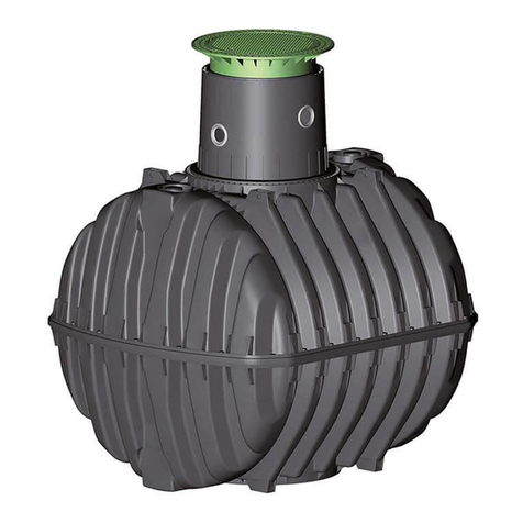
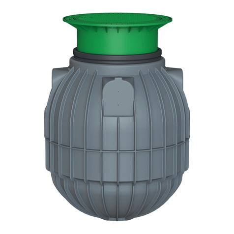
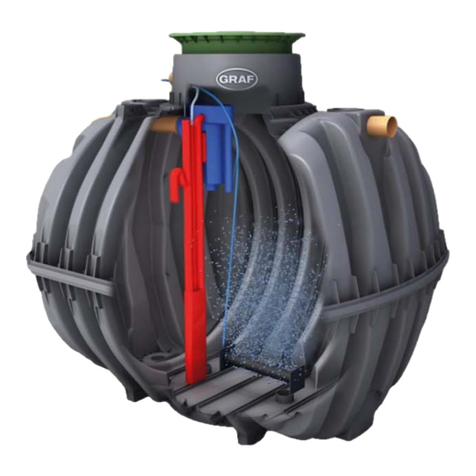
Graf 160470 UPone 3 EW, 2000 L User manual

GRAF UP
DE Montageanleitung für GRAF UP
>> Seite 1-9
EN Assembly instructions for GRAF UP
>> Page 10-18
FR Notice de montage pour GRAF UP
>> Page 19-27
Instrucciones de montaje de la Duperadora GRAF UP
>> Página 28-36
ES

www.graf.info
Montageanleitung für GRAF UP
160470 UPone 3 EW
, 2000 L
160471 UPone 6 EW
, 4000 L
Die in dieser Anleitung beschrie-
benen Punkte sind unbedingt zu
beachten. Bei Nichtbeachtung er-
lischt jeglicher Garantieanspruch.
Für alle über GRAF bezogenen
Zusatzartikel erhalten Sie separate
in der Transportverpackung beilie-
gende Einbau
anleitungen.
Eine Überprüfung der Bauteile auf
eventuelle Beschädigungen hat
unmittelbar nach Anlieferung zu
erfolgen.
Für Betrieb und Wartung der Anla-
ge stehen ihnen auf unserer
Homepage zum Download bereit,
die Links dazu finden Sie im Kapi-
tel 5 dieser Anleitung.
Inhaltsübersicht
1.
LIEFERUMFANG
2
2.
INSTALLATION DER KLÄRTECHNIK
3
2.1
Montage des Tellerbelüfters in den SBR-Behälter
3
2.2
Anschluss der Probeentnahme und Auslauf
4
2.3
Anschluss der Entlüftung
5
3.
MONTAGE SCHALTSCHRANK
6
3.1
Auswahl des Standortes
6
3.2
Technische Daten
6
3.3
Aufstellung und Montage
7
4.
ANSCHLIEßEN DER LUFTSCHLÄUCHE
8
4.1
Anschluss der Luftschläuche
8
5.
INBETRIEBNAHME
9

1. Lieferumfang
2/
1. Lieferumfang
Lieferumfang:
Ein Behälter mit vormontierter Klärtechnik bestehend aus:
xZulaufschikane
xKlarwasserheber
Tellerbelüfter
xRohre und Bögen für Probeentntnahme
PP
-Schaltschrank mit
xKLcontrol.S Steuerung
xLuftverdichter
xSchrittmotorventilen
Nicht im Lieferumfang enthalten sind:
Luftschläuche, benötigt werden: 2 x 19 mm

2. Installation der Klärtechnik
3/
2. Installation der Klärtechnik
Die Behälter sind auf einen ebenen und festen Untergrund zu stellen.
Bei der Wahl des Aufstellortes ist zu beachten, dass die Kläranlage an die, oder ein separates Entlüf-
tungsrohr an die Anlage angeschlossen werden muss.
2.1 Montage des Tellerbelüfters in den SBR-Behälter
Schlauch zum Anschluss des
Tellerbelüfters, vormontiert.
Tellerbelüfter mit beschwertem
Träger
Schnur zum herablassen des
Tellerbelüfters in den Behälter

2. Installation der Klärtechnik
4/
Der Tellerbelüfter wird einzeln mitgeliefert und muss vor dem einbringen in den Behälter mit dem blauen
Luftschlauch im Behälter verbunden werden. Zum Einbringen in den Behälter wird eine Schnur mitgelie-
fert die an dem Tellerbelüfter befestigt wird.
2.2 Anschluss der Probeentnahme und Auslauf
Die Probeentnahme ist entsprechend der oben stehenden Zeichnung zu montieren. Das obere T-Stück
der Probeentnahme kann so ausgerichtet werden, dass diese in die Richtung des geplanten Ablaufrohres
zeigt.
Die Probennahme ist dann mit Rohren und Bögen an das T-Stück DN 110 am Behälter anzuschließen.
T-Stück vormontiert

2. Installation der Klärtechnik
5/
2.3 Anschluss der Entlüftung
An dem außen am Behälter montiertem T-Stück ist eine Entlüftungsleitung anzuschließen.
Die Entlüftungsleitung ist entweder an die Überdachentlüftung anzuschließen, oder separat nach au-
ßen zu führen. Es ist zu beachten, dass aus der Entlüftungsleitung Gerüche austreten können.
DN110

3. Montage Schaltschrank
6/
3. Montage Schaltschrank
3.1 Auswahl des Standortes
Bei der Auswahl des Schaltschrankstandortes müssen Sie folgendes beachten:
xHöhenlage über dem höchstmöglichen Wasserstand im Behälter, um im Havariefall Überflutun-
gen und Wasserzuflüsse im Freispiegel zu vermeiden,
xDer Betrieb erzeugt Geräusche! Der sich im Betrieb befindliche Luftverdichter erzeugt ein länger
anhaltendes Dauergeräusch (vergleichbar mit einem Gefrierschrank).
xDer Maschinenschrank benötigt einen separat abgesicherten Stromanschluss (16 Ampere, träge).
Der Stromanschluss dient als Netz-Trenneinrichtung und muss jederzeit leicht zugänglich sein.
Zusätzliche Stromverbraucher an derselben Sicherung können den Betrieb stören.
xDer Standort des Schaltschrankes muss ein trockener, kühler und gut belüfteter Raum sein. Der
Schrank und insbesondere die Lüftungsöffnungen dürfen nicht abgedeckt bzw. müssen für War-
tungsarbeiten frei zugänglich sein.
xDie Luftschläuche sollen nicht länger als 20 Meter sein.
3.2 Technische Daten
Ausführung:
IP20
Material:
PP
Farbe:
schwarz
Schließung:
Schraubensicherung an der Frontseite, mittig
Elektrischer Anschluss:
Vorsicherung bauseits erforderlich
1~ 230V, 50 Hz
Anschlüsse am
Schaltschrank:
Drucklufttüllen: 2
x 19mm
Anschlussleitung mit Stecker
-Typ E+F Abmessungen des PP-Schrankes
420
280
275
625

3. Montage Schaltschrank
7/
3.3 Aufstellung und Montage
NInhalt des Beutels mit Montagematerial
1
Kunststoffdübel
2
Gummi -Unterlegscheibe
3
Unterlegscheibe Stahl
4
Stockschraube M8x10
5
Unterlegscheibe Stahl
6
Zahnscheibe
7
Mutter M8
8
Schraube M4x20 als Kindersi-
cherung für den Deckel
Benötigtes Werkzeug
Bohrer M10
Maulschlüssel SW13
Bit TX25 für Stockschraube
Bit H2 für Schrankdeckel
Die Befestigung des PP-Schrankes erfolgt mit 4 Stockschrauben ③, die mit Dübeln ①in der Wand befes-
tigt werden. Die Unterlegscheiben, Zahnscheiben, Muttern sind entsprechend der oben stehenden Abbil-
dung zu montieren.
Nach der Montage ist der Deckel mit der Schraube M4x20 zu sichern. Als Ersatz wird eine zweite
Schraube mitgeliefert.
ཱ
ི
ྲྀ
ཱི
ུ
ཱུ

4. Anschließen der Luftschläuche
8/
4. Anschließen der Luftschläuche
4.1 Anschluss der Luftschläuche
Die Belüftung und der Klarwasserheber der UPone ist mit Schläuchen (19 mm Innendurchmesser) mit
dem Schaltschrank zu verbinden.
Farbmarkierung am
Schaltschrank
Bezeichnung des
Ventils
Belüftung (Tellerbelüfter)
blau
Y1
Klarwasserabzug
schwarz
Y2
Die Schläuche sind mit Schlauchschellen zu fixieren.

5. Inbetriebnahme
www.graf.info
9/
07-2021
5. Inbetriebnahme
Zur Inbetriebnahme sind alle Behälter mit Frischwasser zu befüllen, ebenso die Probeentnahme.
Der Schukostecker des Schrankes ist an der Steckdose anzuschließen. Beim PP-Schrank startet nun die
Steuerung.
Vor Inbetriebnahme ist das Betriebsbuch zu lesen und zu beachten!
Der Betrieb und die Wartung ist in Anlehnung
des Betriebsbuchs
der easyOne durch-
zuführen. In
dem Betriebsbuch
ist auch die Bedienung der Steuerung ausführlich be-
schrieben.
Das Betriebsbuch stellen wir Ihnen zum Download auf unserer Webseite bereit:
UPone (Betriebsbuch easyOne):
https://www.graf
-online.de/fileadmin/media/Betriebsbuch_KKA_easyOne_DE.pdf

www.graf.info
Assembly instructions for GRAF UP
160470 UPone 3 EW, 2,000
L
160471 UPone 6 EW, 4,000
L
The subjects described in this in-
struction manual must be ob-
served. Non
-
observance will void
all warranty claims. For all addi-
tional articles purchased via GRAF
you will receive separate installa-
tion instructions enclosed in the
transport packaging.
The p
arts must immediately be
inspected for damage after deliv-
ery.
Manuals for operation and mainte-
nance of the system can be down-
loaded from our website. For the
links, see chapter 5 of this instruc-
tion manual.
Table of contents
1.
SCOPE OF DELIVERY
2.
INSTALLATION OF THE SEWAGE TREATMENT
TECHNOLOGY
2.1
Assembly of the disc diffusor in the SBR tank
2.2
Connecting the sampling unit and drain
2.3
Connecting the venting system
3.
ASSEMBLY OF THE CONTROL CABINET
3.1
Selecting the location
3.2
Technical Data
3.3
Installation and assembly
4.
CONNECTING THE AIR HOSES
4.1
Connection of the air hoses
5.
COMMISSIONING

1. Scope of delivery
/
1. Scope of delivery
UPone
Scope of delivery:
A container with pre
-installed sewage treatment technology, comprising:
xSupply baffle
xClean water lifter
Disc diffusor
xPipes and bends for sampling unit
PP
-control cabinet with
xKLcontrol.S control
xAir compressor
xStep motor valves
Not included are:
Required air hoses: 2 x 19
mm

2. Installation of the sewage treatment technology
/
2. Installation of the sewage treatment technology
The tanks must be placed on a level and firm base.
When selecting the location for the treatment plant, note that the sewage treatment facility must be con-
nected to the roof ventilation, or that a separate ventilation pipe must be connected to the facility.
2.1 Assembly of the disc diffusor in the SBR tank
Hose to connect the disc diffusor,
pre
-installed.
Disc diffusor with weighted carrier
Cord to lower the disc diffusor into
the tank

2. Installation of the sewage treatment technology
/
The disc diffusor is enclosed separately and must be connected to the blue air hose in the tank before
introduction into the tank. A cord for introduction into the tank is enclosed. It is attached to the disc diffu-
sor.
2.2 Connecting the sampling unit and drain
The sampling unit must be installed according to the above drawing. The upper tee of the sampling unit
can be aligned so that it shows the direction of the planned drainpipe.
The sampling unit is then connected to the tee DN 110 at the tank with pipes and bends.
Pre-installed tee

2. Installation of the sewage treatment technology
/
2.3 Connecting the venting system
A venting line must be connected to the tee installed on the outside of the tank.
The venting line either needs to be connected to the roof venting or routed outside separately. Note
that odours may escape from the venting line.
DN110

3. Assembly of the control cabinet
/
3. Assembly of the control cabinet
3.1 Selecting the location
When selecting the location for the control cabinet, the following must be considered:
xThe control cabinet must be mounted above the highest water level in the tank to avoid overflow-
ing and water intake by gravity in case of an accident.
xThe system generates noise! When operating, the air compressor generates continuous noise
(comparable to that of a freezer).
xThe machine cabinet requires a separately protected electrical connection (16 amp, slow blow).
The electrical connection serves as a mains disconnecting device and must be easily accessible
at all times. Additional electrical fixtures on the same fuse may disrupt operation.
xThe location of the control cabinet must be a dry, cool and well-ventilated room. The cabinet, in
particular the ventilation vents, must not be covered and must be freely accessible for mainte-
nance work.
xThe air hoses should be no longer than 20 metres.
3.2 Technical Data
Model
:IP20
Material:
PP
Color
:black
Shutting
:
Sc
rew lock centered at the front cover
Electrical connection
:
Back
-up fuse required on site
1
~ 230V, 50 Hz
Connections at the cabinet
:
Compressed air nozzles: 2
x19mm
Connection cable with plug t
ype E+F Dimensions of the PP Cabinet
420
280
275
625

3. Assembly of the control cabinet
3.3 Installation and assembly
Assembly material bag content
1
Plastic dowels
2
Washer, rubber
3
Washer, steel
4
Hanger bolt M8x10
5
Washer, steel
6
Toothed lock washer
7
Nut M8
8
Screw
M4x20 as child safety
lock for the cover
Required tools
Drill M10
13 mm open-end wrench
Bit TX25 for hanger bolt
Bit H2 for cabinet cover
The PP cabinet is mounted using 4 hanger bolts ③and plastic dowels ①fixed in the wall. Assemble the
washers, toothed lock washers and nuts as illustrated in the above figure.
When mounted, secure the cover using the M4x20 screw. A second screw is included for replacement.
ཱ
ི
ྲྀ
ཱི
ུ
ཱུ

4. Connecting the air hoses
/
4. Connecting the air hoses
4.1 Connection of the air hoses
Venting and the clear water lifter of the UPone must be connected to the control cabinet with hoses
(19 mm inner diameter).
Colour mark at the
control cabinet
Designation of the
valve
Aeration (disc diffusor)
blue
Y1
Clear water extraction
black
Y2
The hoses must be fastened with hose clamps.

5. Commissioning
www.graf.info
/
07-2021
5. Commissioning
For commissioning, fill all tanks and the sampling unit with fresh water.
The two-pin earthed plug of the cabinet must be connected to the power socket. Now the PP cabinet con-
trol starts.
Please read and note the operating manual before start-up!
Operation and maintenance are in alignment with the operation manuals of the
one2clean plus. The operating manuals describe operation of the control in detail as
well.
You can download the operating manual from our website:
UPone (operating manual one2clean plus
):
https://www.graf
-water.com/
fileadmin/media/EBA_Betriebsbuch_one2clean_plus_one2clean_plus_XXL_EN.pdf

www.graf.info
Notice de montage pour GRAF UP
160470 UPone 3 EH, 2000 L
160471 UPone 6 EH
, 4000 L
Afin de garantir le bon fonctionne-
ment et la longévité de votre instal-
lation, les différents points décrits
dans cette notice doivent être
scrupuleusement respectés. Tout
manquement à ces règles annule-
ra systématiquement la garantie.
Lisez également toutes les notices
des autres éléments fournis par la
société GRAF. Vous trouverez les
notices de montage jointes dans
l’emballage.
Vérifier les composants immédia-
tement après la livraison afin de
détecter d'éventuels dommages.
Une notice d’utilisation et de main-
tenance est disponible sur notre
site internet, voir § 5 de cette no-
tice.
Sommaire
1.
ÉTENDUE DE LA LIVRAISON 2
2.
INSTALLATION DU SYSTEME DE TRAITEMENT
2.1
Montage du plateau membrane dans le réservoir SBR
2.2
Raccordement du bac de prélèvement et de
l’évacuation
2.3
Raccordement de la ventilation
3.
MONTAGE DE L’ARMOIRE DE PILOTAGE
3.1
Choix de l'emplacement
3.2
Données techniques
3.3
Installation et montage
4.
RACCORDEMENT DES TUYAUX D'AIR
4.1
Raccordement des tuyaux d'air pour UPone
5.
MISE EN SERVICE
This manual suits for next models
1
Table of contents
Languages:
Other Graf Tank Equipment manuals
Popular Tank Equipment manuals by other brands

Cordivari
Cordivari Bolly1 PDC user manual

Cumberland
Cumberland PNEG-1096 Assembly manual

CEMO
CEMO KS-MOBIL 980 Installation and operating instructions

VIAIR
VIAIR 91025 user manual

BE Ag & Industrial
BE Ag & Industrial DD400 Operations & parts manual

Torklift
Torklift A7770 Important owner-operator installation instructions