MV-42HS
Quick Setup Guide
Use SDI and DVI monitors that support 1920 x
1080 (59.94 or 50) interlaced and/or 1280 x
720 (59.94 or 50) progressive video signals.
Packing list: MV-42HS:1, CD-ROM:1 (Operation Manual)
Option items:
MV-42AI (installed)
MV-42IF/IFA (installed)
AC adapter (including AC cord, AC adaptor retaining clip)
Rack mount bracket set
Precautions
⚫Operate the unit only at the specified supply voltage.
⚫Ensure the power cord and connectors are firmly connected.
⚫Do not access circuitry with power applied to the unit.
⚫Unit should not be operated or stored with the cover, panels, and/or casing removed.
⚫Unit should not be operated or stored in a humid, dusty, etc. environment. Doing so could result in
fire or electrical shock.
⚫Do not allow fluids, metal fragments, or any other foreign objects to enter the unit. If foreign matter
does enter the unit, turn the power off and disconnect the poser cord immediately. Remove the
material or contact your authorized service representative
⚫If you notice any strange smells or noises coming from the unit, turn power off immediately, turn OFF
the power switch, disconnect the power cord, then contact your authorized service representative.
If the newly connected monitor does not support the current output format and
cannot display anything on the monitor screen, you can change output formats and
have it display the output format on screen using a format changeover feature. The
factory default output format is 1080/59.94i.
Turning the unit power on while pressing a button ( 1 through 4) starts the system in
the corresponding format, whichis displayed on screen. The MV-42HS is then set to
always output in the selected format.
When Nothing Appears on the Monitor!
To display your desired channel in Full Screen mode, press the corresponding button from among buttons
1 to 4. For instance, to view channel 3 in Full Screen, press button 3.
* A black screen is shown for any channel without an input signal.
To Display in Full Screen Mode
The AUTO button initiates sequential display of channels 1 through 4 in Full Screen mode. Channels
without an input signal will be skipped. Press the 1 , 2 , 3 , 4 , or MULTI button to stop sequential
display.
* The switching interval can be set in the AUTO SEQUENCE TIME menu.
To Sequentially Display Channels in Full Screen
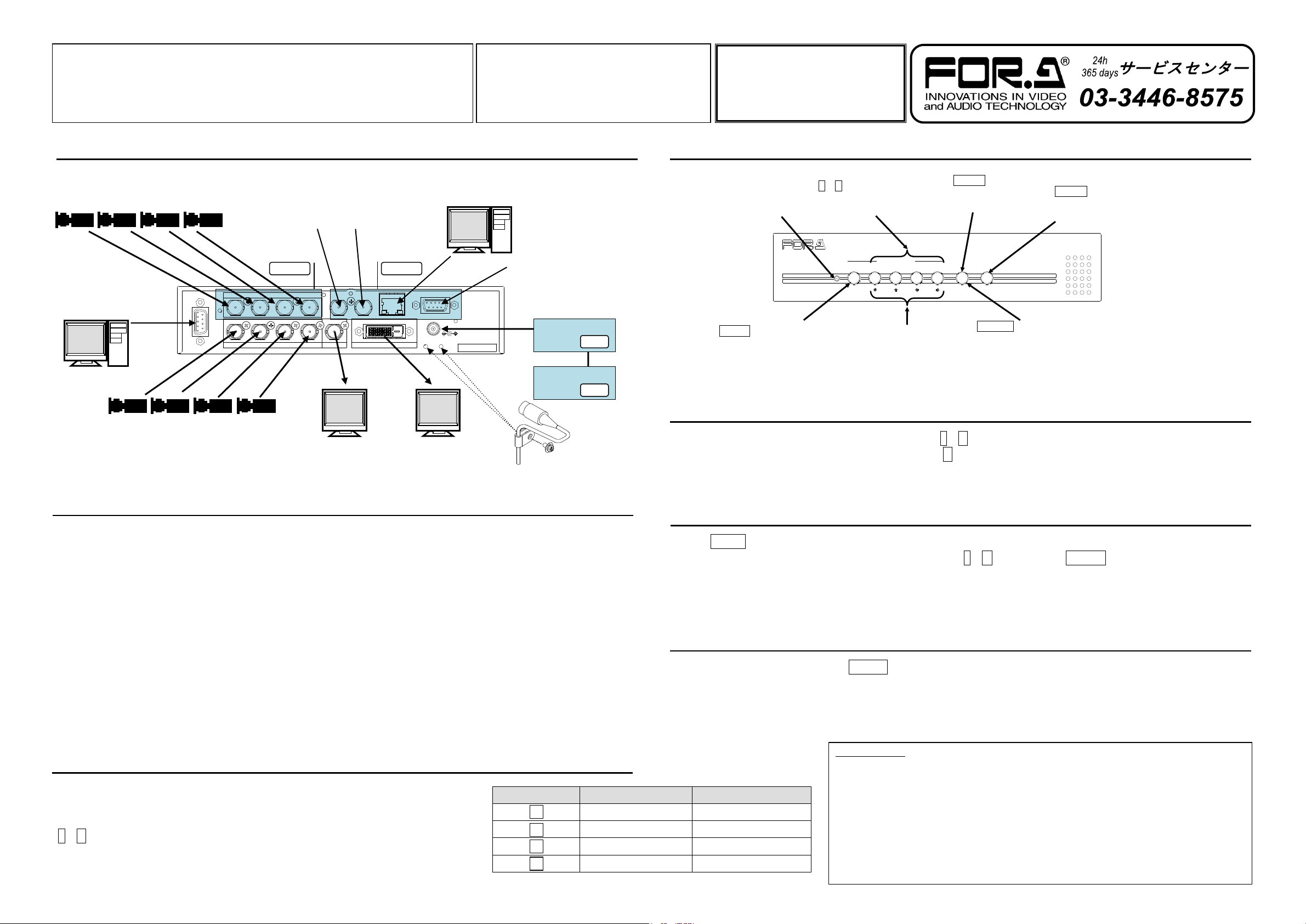
1) Apply DC power to the MV-42HS using an AC adapter.
* The unit turns on when the power is applied. There is no ON/OFF switch.
2) Connect an SDI and/or DVI monitor.
3) Connect signal source devices, such as video cameras, to the HD/SD-SDI IN and/or ANALOG COMPOSITE
IN connectors.
* To use analog composite signals, go to [SYSTEM 2/2]>[INPUT] in the menu and change input source
settings.
4) Connect a PC to be used for remote control using an RS-232C straight cable.
5) Connect a switcher, etc. for tally inputs.
6) Connect a PC to be used for remote control to the MV-42HS LAN connector using a LAN cable.
* Use a crossover LAN cable when connecting the MV-42HS directly to a PC. Use a straight LAN cable when
connecting the MV-42HS and PC through a hub.
7) Input a BB or tri-level sync signal.
8) Input a time code to be used for Time display.
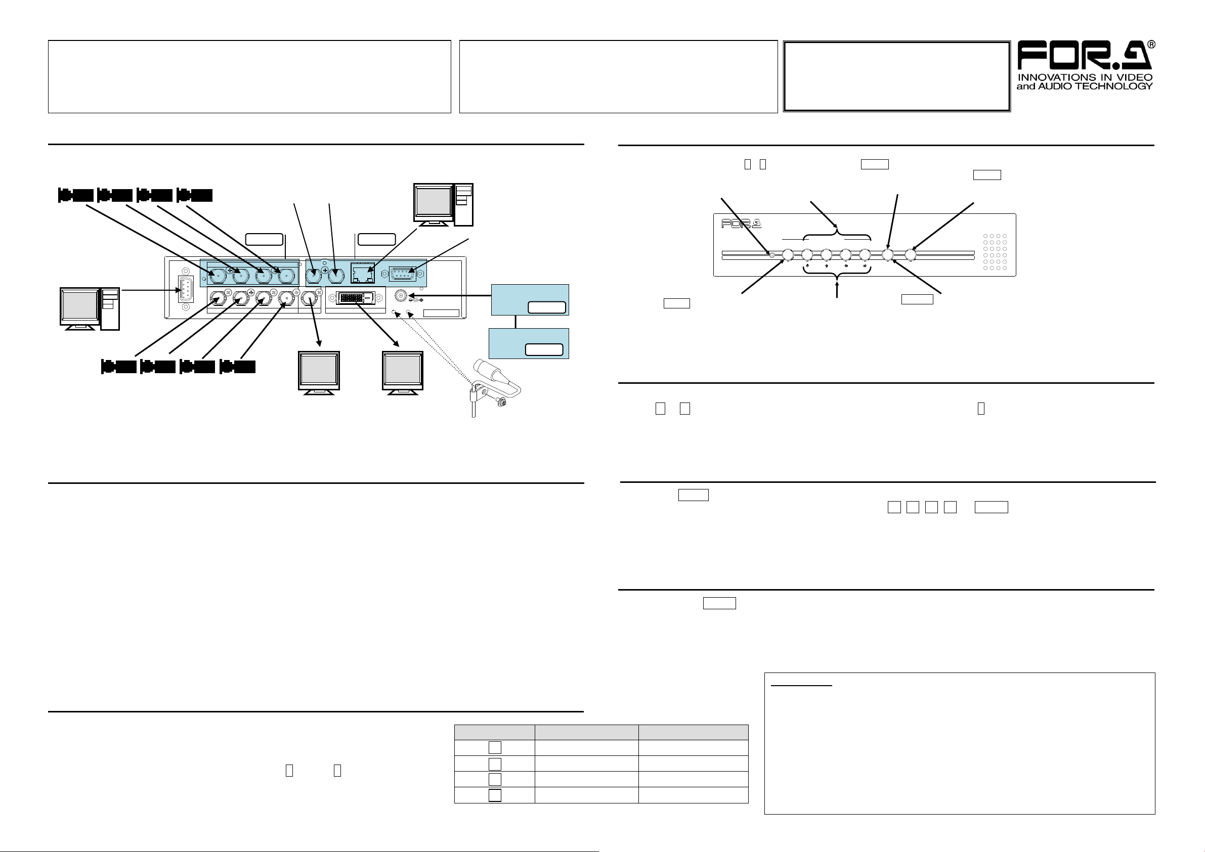
POWER AUTO 1 2 3 4
FULL SCREEN MULTI
ENTER
MENU
MV - 42HS
MULTI VIEWER
AUTO button
(Sequentially displays
channels 1 through 4 in
full screen.)
1~4 (Full screen) buttons
(Each button displays the
corresponding channel
signal in full screen.)
MULTI button
(Changes display mode to
multi-channel screen.)
Arrow buttons
(Works as arrow buttons while a
menu is open to navigate or
change menu values.)
MENU button
(Hold down at least 2
seconds to access menus.)
ENTER button
(Used to confirm settings or go to submenus
for menu operation. Pressing an arrow button
while holding down the ENTER button allows
to change values by 10 or 100.)
Press the MULTI button to display a multi-channel screen.
* A black screen is shown for any channel without an input signal.
* Select quad or Right-left split-screen in the [MULTI CH SCREEN SETUP] > [DISPLAY TYPE] menu or
via the command protocol.
To Display a Multi-channel screen
RS- 232C
1
1
2
2
3
3
4
4
HD/ SD- SDI IN
ANALOG COMPOSITE IN REF IN LTCIN
HD-SDI OUT DVI-D OUT
LAN
REMOTE/ TALLY
DC12VIN
SER. NO.
ANALOG COMPOSITE IN (1-4)
(Connect video cameras, etc. to
input analog composite signals.)
LAN
(Connect a PC for remote control
using command protocols.)
REF IN
(Input an external
reference signal to
synchronize
HD-SDI signals.)
LTC IN
(Input a time code
to synchronize the
time display.)
HD/SD-SDI IN (1-4)
(Connect video cameras, etc. to input
HD/SD-SDI signals. Auto format detection)
HD-SDI OUT
(Connect an SDI monitor
to output video signals.)
DVI-D OUT
(Connect a DVI monitor
to output video signals.)
REMOTE/TALLY
(Connect a
production or routing
switcher for (red and
green) tally inputs
and remote control.
RS-232C
(Connect a PC for
title settings and
remote control using
command protocols.)
Secure the AC adaptor
DC cord with the attached
DC cord retaining clip.