manuals.online logo
Brands
  1. Home
  2. •
  3. Brands
  4. •
  5. FOR-A
  6. •
  7. Media Converter
  8. •
  9. FOR-A USF-212BS User manual

FOR-A USF-212BS User manual

USF212BS_SETUPGUIDE-E-1.DOCX
USF-212BS
Quick Setup Guide
1. AC Cord Clamp Installation
1) Insert the anchor into the hole next to the AC inlet.
2) Plug in the AC cord.
3) Adjust the strap length to fit.
4) Wrap the AC cord clamp around the AC cord.
5) Gently pull on the AC cord to ensure it has been securely plugged in.
2. Opening / Closing the Front Panel
Opening the Front Panel Closing the Front Panel
The front panel may be difficult to open or close if the USF frame
is placed on a desk, and may be damaged if it is forced to open.
Perform the following steps after setting the frame in a rack.
When the front panel is being opened, one short beep sounds
every 30 seconds to notify the user and after 5 minutes (default
setting), the short beep changes to normal alarm buzzer. When
performing installation or other modification while the power is on,
complete the procedure in a short period of time.
Twenty seconds after the front panel is installed, all LEDs
on the front panel light up.
If not, the front panel has not been installed properly. Re-
install the front panel.
3. Detaching / Attaching the Front Panel
Detaching the Front Panel Attaching the Front Panel
4. Front Interior
The slot configuration as shown below is revealed when the front panel is removed.
No.
Slot Type
Description
(1)
Power Supply 1 Slot
Dedicated power unit installed in this slot as standard.
Power is supplied when the power supply switch is turned on.
(2)
Power Supply 2 Slot
Slot for redundant power supply USF-212PS. Redundant operation available when optional USF-
212PS is installed. A blank panel will otherwise cover the slot.
(3)
Control Card Slot
Slot for network control card.
Enables SNMP monitoring through LAN ports on the rear panel and alarm output from the ALARM
connector and allows control over the all slot modules..
(4)
USF Module Slots
Dedicated USF module slots. (Front USF modules)
For details on module operation, refer to the respective operation manuals.
Packing list
USF-212BS: 1
AC Cord: 1 set DVD-ROM: 1
Quick Setup Guide: 1 (This guide)
Pull out the front panel.
The front panel rails
can be tilted down.
1
2
3
4
5
6
7
8
10
9
11
12
USF-212BS
UNIVERSALS YSTEMFRAME
GENLOCK 1
POWERO N
GENLOCK 2
ALA RM
DC 1
DC 2
FAN
BUZZER
OFF
159
2610
3
4
7
8
11
12
1
2
3
4
5
6
7
8
10
9
11
12
USF-212BS
UNIVERSALS YSTEMFRAME
GENLOCK 1
POWERO N
GENLOCK 2
ALA RM
DC 1
DC 2
FAN
BUZZER
OFF
159
2610
3
4
7
8
11
12
Loosen the two thumbscrews on the front panel by
turning them counterclockwise.
Pull out the front panel using the pull handles.
The fan stops while the front panel is open.
(1)
(2)
(3)
(4)
SLOT1
SLOT2
SLOT3
SLOT4
SLOT5
SLOT6
SLOT7
SLOT8
SLOT9
SLOT10
SLOT11
SLOT12
The front panel can be
detached by gently pushing
both rails inward.
Fully draw out the front
panel.
Grab both handles, tilt up
the front panel until it
aligned and push the front
panel back into the frame
body.
1
2
3
4
5
6
7
8
10
9
11
12
USF-212BS
UNIVERSALS YSTEMFRAME
GENLOCK 1
POWERO N
GENLOCK 2
ALA RM
DC 1
DC 2
FAN
BUZZER
OFF
159
2610
3
4
7
8
11
12
If the frame is powered on, the POWER LED lights green
and fans begin to work once the front panel is properly
installed. If the LED does not light up, grab both handles
and push the panel until it is tightly fitted into place.
1
2
3
4
5
6
7
8
10
9
11
12
USF-212BS
UNIVERSALS YSTEMFRAME
GENLOCK 1
POWERO N
GENLOCK 2
ALA RM
DC 1
DC 2
FAN
BUZZER
OFF
159
2610
3
4
7
8
11
12
Tighten two screws in both sides to secure the
front panel.
Gently push rails on both sides inward to
respectively fit the tab into the aperture of
the guide rail. Handle the front panel
carefully so as not to bend the rails.
Push the front panel straight
into the frame body.
http://www.for-a.com/
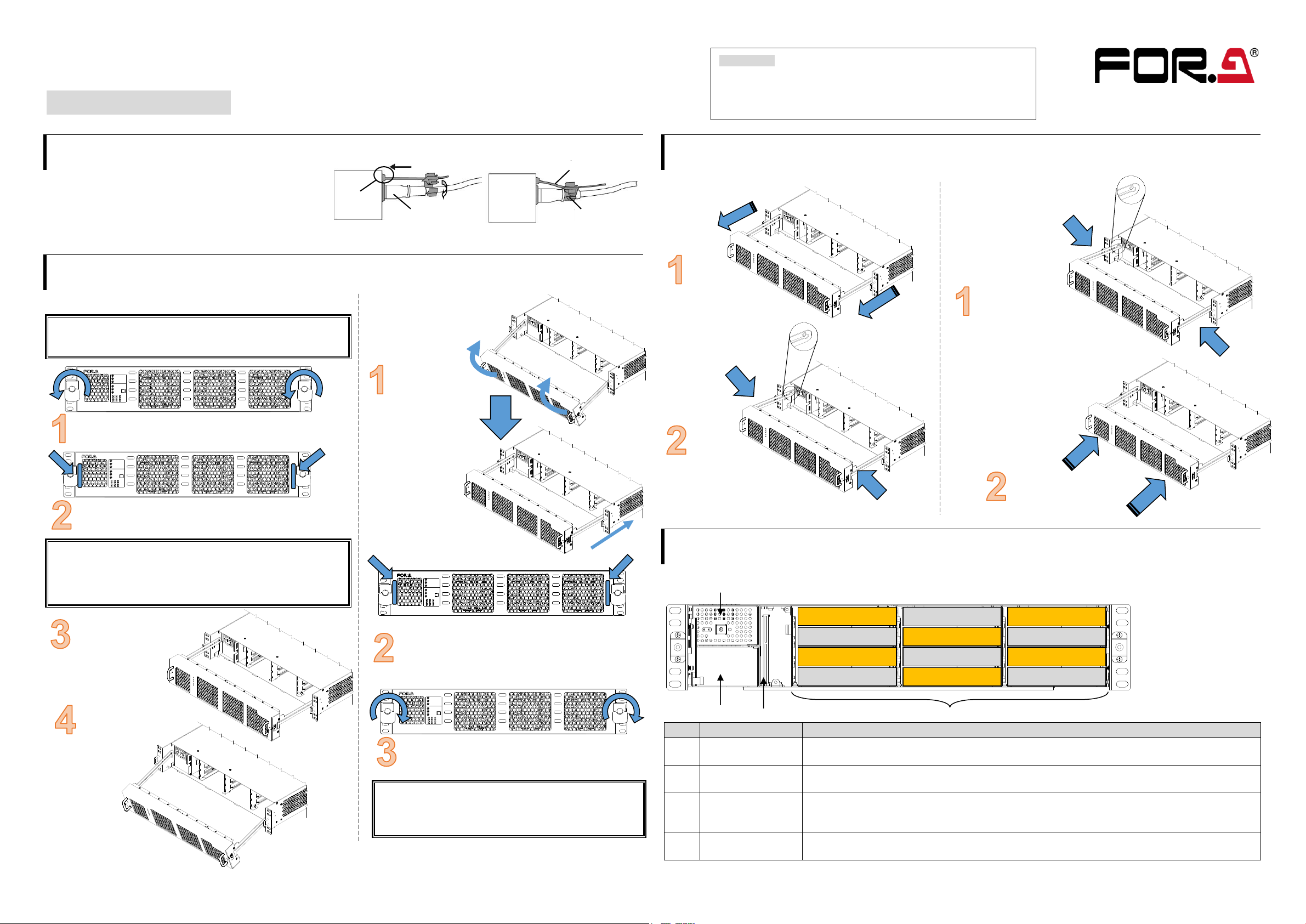
5. USF Module Installation
Module installable slots vary depending on the USF module type. (See “Installation Slots for Front and Rear Modules”below.)
If multiple free slots exist, do not install modules side-by-side but leave slots open to prevent overheating.
The procedure for installing the USF module in Slot 1 is described below as an example.
Installing USF Rear Module
Installing a USF Front Module
* Always install the rear module first, then the front module.
(1) Slot 1 is the top slot in the right block of the front panel. (Refer to 4. “Front Interior”)
(2) Set the front module on the guide rail and carefully insert the front module slowly.
(3) Push the handle until the front module clicks into the connectors.
Always use handles when inserting modules. Otherwise, the modules may be damaged.
Installation Slots for Front and Rear Modules
* Refer to Module Operation Manuals for USF-10IP series.
<TYPE1> <TYPE2>
Front: 1 slot (All slots) Front: 1 Slot (Even slots only)
Rear: 1 slot (All slots) Rear: 2 Slots (Upper and Lower)
<TYPE3>
Front: 1 slot (Odd slots only) Modules that can be remotely controlled from a PC
Rear: 2 slots (Upper and lower) require installation of both Processor Control GUI
Launcher and GUI Control Software.
・USF modules come as front and rear sets. Be sure to install set modules (front and rear) into their proper slots.
・Install blank panels over free slots to prevent foreign material from entering and overheating the chassis.
IMPORTANT
・Beware of the occurrence of electrical breakdown in USF Modules.
・Wear an antistatic wrist strap or equivalent to equalize the electrical potential of the USF-212BS unit and the
worker’s body. Do not touch the PCB wiring or parts legs directly with your fingers while working.
・Each USF Module can be installed and uninstalled while the power is on in case of emergency. Shut down the
power for non-emergency work.
・When front module is being installed / uninstalled while the power is on, the front panel is in open state. The fan
will stop during the procedure, so it is essential to complete the installation within a short period and to close the
front panel immediately.
・Be sure to shut down the power to install and uninstall a control module.
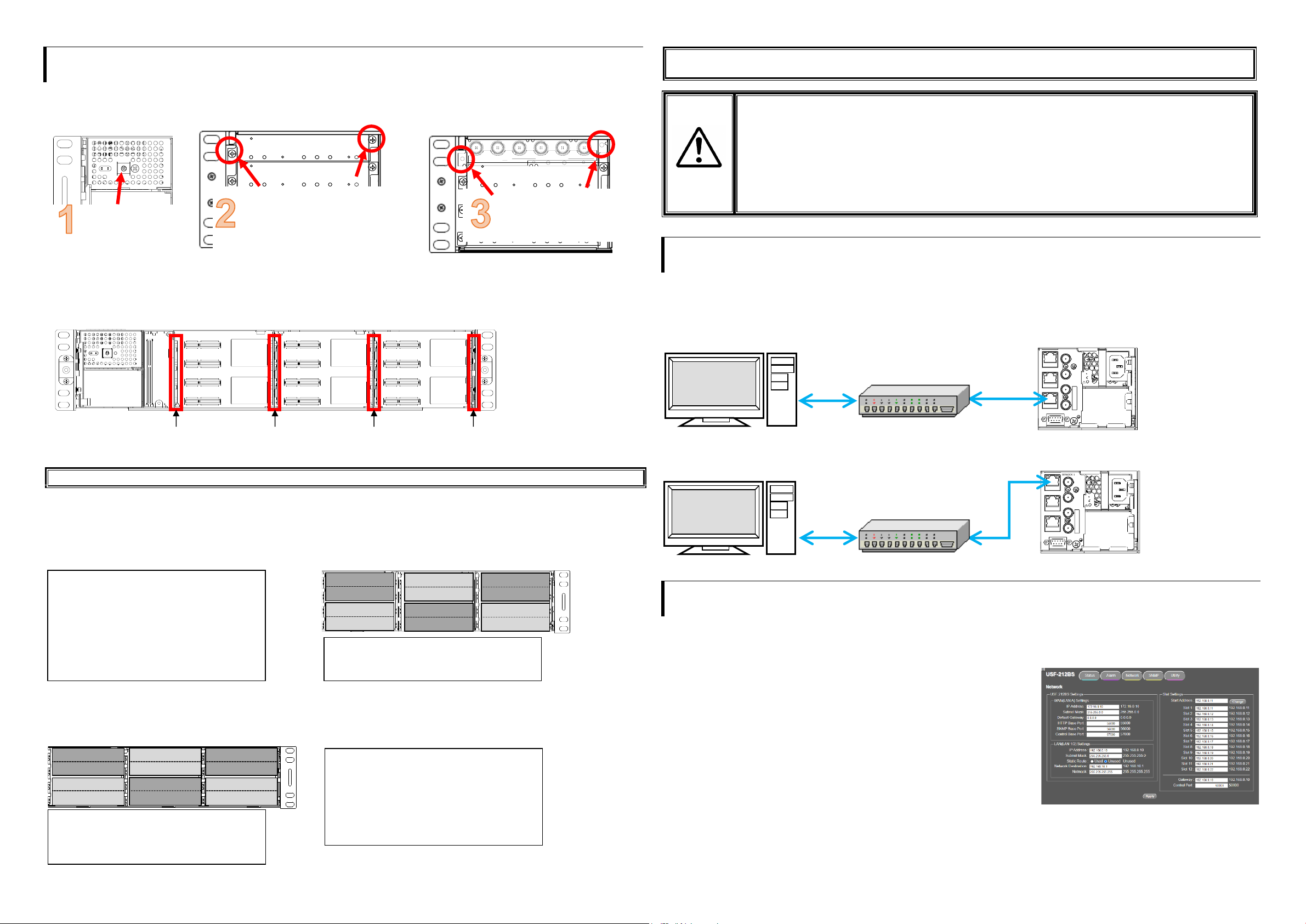
6. Connecting USF-212BS from a PC
USF-212BS can be monitored by the Web GUI or an SNMP Manager and generate alarms to indicate errors or warnings over LAN.
The module provides two LAN connection ports: LAN1/2 or LAN A. Select one of them according to the system.
There are two ways to connect to USF-212BS from a PC: Using LAN1/2 port or LAN A port. Connect to fit your system.
Connecting via LAN A
Connecting via LAN1 or LAN2
Connect to LAN1 or LAN2 on the rear panel. (Example below: LAN1)
7. Network Default Setting
Open the web browser of the PC and input address. A status page as shown opens on the web browser when connection is
established.
Connecting to LAN A: http://172.16.0.10/ (Factory Setting)
LAN1 または LAN2 と接続しているとき:http://192.168.0.10/ (Factory Setting)
IP Address Change
(1) Click the Network tab.
(2) Input new IP address into the IP Address box of WAN (LAN A) Settings to
change LAN A IP address.
Input new IP address into the IP Address box of LAN (LAN1/2) Settings to
change LAN 1/2 IP address.
(3) A confirmation message window opens when you click Apply.
Click OK in the confirmation window.
(4) Click Utility tab, then click Restart.
Click OK when the restart confirmation window opens.
USF-212BS restarts. The new setting is reflected after the restart.
NOTE) IP addresses are assigned to respective USF-212BS modules installed.
Refer to USF-212BS operation manual Sec. “USF-212BS WEB GUI” for details on setting IP addresses.
Open the front panel
and shut down the
USF-212BS power
supply.
Slot 1 is the top slot in the left module
block on the rear panel. Remove the
blank panel by detaching the two
screws on both ends. Keep the blank
panel and screws in a safe place after
removal.
3G/HD/SD SDI IN
USF-1043FS
1 2 1 2 3 4
3G/HD/SD SDI OUT
Insert the rear module into
the slot and fasten both
supplied screws.
Installable modules
105DADA 402AADC
108ADA 1013MUX
1040VEA 1013DEMUX
1053DDA 1043FS
105DDA-12G 105FS-12G
105DDA-12GA 1043VM
204ADAC 80SDICS
Installable modules:
1100VEA 1043SS
1044UDC 1043VTG-LI
SLOT 12
SLOT 2
SLOT 4
SLOT 6
SLOT 8
SLOT 10
Installable modules:
106UDC-12G 101MDX4-12G
106DC-12G 101MDX8-12G
106TICO-12G 111DDA-12G
SLOT 1
SLOT 3
SLOT 5
SLOT 7
SLOT 11
SLOT 9
Available modules:
106UDC-12G 106DC-12G
101MDX4-12G 101MDX8-12G
105FS-12G 106TICO-12G
See the Processor Control GUI Launcher
Operation Manual for details
PCB Guide Rail
PCB Guide Rail
PCB Guide Rail
PCB Guide Rail
USF-212BS
ALARM
SER.NO. 2
AC100-240V 50/60Hz IN AC100-240V 50/60Hz IN 1
GENLOCK 2
GENLOCK 1
LAN A
LAN 2
LAN 1
LAN 1/2 IP Address
Factory default
192.168.0.10
Slot1 to 12 IP Address
Factory default
192.168.0.11
to 192.168.0.22
LAN1 LED (LAN2 LED)
Lit Green: Connected
Flashing Orange
: Transmitting
and receiving data
USF-212BS Rear Panel
Web browser
SNMP manager
USF-212BS
ALARM
SER.NO. 2
AC100-240V 50/60Hz IN AC100-240V 50/60Hz IN 1
GENLOCK 2
GENLOCK 1
LAN A
LAN 2
LAN 1
LAN A IP Address
Factory default
172.16.0.10
LAN A LED
Lit Green: Connected
Flashing Orange: Transmitting
and receiving data
USF-212BS Rear Panel
Web browser
SNMP manager

Other FOR-A Media Converter manuals

FOR-A UFM-30UDC User manual

FOR-A

FOR-A UFM-30UDC User manual

FOR-A MV-42HS User manual

FOR-A

FOR-A MV-42HS User manual

FOR-A FA-9600 User manual

FOR-A

FOR-A FA-9600 User manual

FOR-A UFH-70DAC User manual

FOR-A

FOR-A UFH-70DAC User manual

FOR-A USF-106UDC-12G User manual

FOR-A

FOR-A USF-106UDC-12G User manual

FOR-A DCC-100 User manual

FOR-A

FOR-A DCC-100 User manual

FOR-A VTW-350HS User manual

FOR-A

FOR-A VTW-350HS User manual

FOR-A FRC-9100 User manual

FOR-A

FOR-A FRC-9100 User manual

FOR-A MV-42HSA User manual

FOR-A

FOR-A MV-42HSA User manual

FOR-A HVS-2000DVE User manual

FOR-A

FOR-A HVS-2000DVE User manual

FOR-A UFH-70DCM User manual

FOR-A

FOR-A UFH-70DCM User manual

Popular Media Converter manuals by other brands

DesignTech MIPC-1A quick start guide

DesignTech

DesignTech MIPC-1A quick start guide

RKC INSTRUMENT COM-JL instruction manual

RKC INSTRUMENT

RKC INSTRUMENT COM-JL instruction manual

Uhlenbrock Elektronik 75 100 user manual

Uhlenbrock Elektronik

Uhlenbrock Elektronik 75 100 user manual

Baumer HUBNER BERLIN HOG 75 D1C Mounting and operating instructions

Baumer

Baumer HUBNER BERLIN HOG 75 D1C Mounting and operating instructions

LG RBD154K owner's manual

LG

LG RBD154K owner's manual

CYP EL-8500VA Operation manual

CYP

CYP EL-8500VA Operation manual

AUDIOBYTE Hydra VOX owner's manual

AUDIOBYTE

AUDIOBYTE Hydra VOX owner's manual

Linear Technology DC2221A Demo Manual

Linear Technology

Linear Technology DC2221A Demo Manual

Cameo iDMX Core user manual

Cameo

Cameo iDMX Core user manual

Atlona AT-VGA300CV Operation manual

Atlona

Atlona AT-VGA300CV Operation manual

Denon S-52 Service manual

Denon

Denon S-52 Service manual

StarTech.com 25SAT35HDD Quick install guide

StarTech.com

StarTech.com 25SAT35HDD Quick install guide

Explore EP9134 user guide

Explore

Explore EP9134 user guide

Cerevo CDP-WF01 Quick setup guide

Cerevo

Cerevo CDP-WF01 Quick setup guide

Cypress CP-261H Operation manual

Cypress

Cypress CP-261H Operation manual

TR-Electronic Profibus 582 Series Assembly instructions

TR-Electronic

TR-Electronic Profibus 582 Series Assembly instructions

CYP AU-D250 Operation manual

CYP

CYP AU-D250 Operation manual

Baumer HOG 9 Installation and operating instructions

Baumer

Baumer HOG 9 Installation and operating instructions

manuals.online logo
manuals.online logoBrands
  • About & Mission
  • Contact us
  • Privacy Policy
  • Terms and Conditions

Copyright 2025 Manuals.Online. All Rights Reserved.