FOR-A USF-106UDC-12G User manual

USF-106UDC-12G
4K Up/Down-Converter
USF-106DC-12G
4K Down-Converter
USF-10UDC-AHDR
USF-10DC-AHDR
2nd Edition - Rev. 1
OPERATION
MANUAL

2
Precautions
Important Safety Warnings
[Power]
Stop
Do not place or drop heavy or sharp-edged objects on the power cord. A damaged
cord can cause fire or electrical shock hazards. Regularly check the power cord for
excessive wear or damage to avoid possible fire / electrical hazards.
[Circuitry Access]
Stop
Do not touch any parts / circuitry with a high heat factor.
Capacitors can retain enough electric charge to cause mild to serious shock, even after
the power has been disconnected. Capacitors associated with the power supply are
especially hazardous.
Hazard
Unit should not be operated or stored with cover, panels, and / or casing removed.
Operating the unit with circuitry exposed could result in electric shock / fire hazards or
a unit malfunction.
[Potential Hazards]
Caution
If abnormal odors or noises are noticed coming from the unit, immediately turn the
power off and disconnect the power cord to avoid potentially hazardous conditions. If
problems similar to the above occur, contact an authorized service representative
before attempting to operate the unit again.
[Consumables]
Caution
Consumable items that are used in the unit must be periodically replaced. For further
details on which parts are consumables and when they should be replaced, refer to the
specifications at the end of the Operation Manual. Since the service life of the
consumables varies greatly depending on the environment in which they are used,
such items should be replaced at an early date. For details on replacing consumable
items, contact your dealer.

3
Upon Receipt
USF-106UDC / DC-12G cards and their accessories are fully inspected and adjusted prior to shipment.
Check your received items against the packing lists below. Check to ensure no damage has occurred
during shipment. If damage has occurred, or items are missing, inform your supplier immediately.
USF-106UDC / DC-12G Box
ITEM
QTY
REMARKS
USF-106UDC-12G or
USF-106DC-12G
1
Front module
Rear module
DVD-ROM
1
Installation disc
-USF-106UDC/DC-12G GUI Software
-USF-GUI-Launcher (Connection Manager)
Including the following PDF manuals
-USF-106UDC/DC-12G Operation Manual
-USF-GUI-Launcher Operation Manual
Software Option
USF-10UDC-AHDR or
USF-10DC-AHDR
1
HDR Expansion option
Remote Control Option
FA-10RU
1
Trademarks
* Microsoft, Windows and Internet Explorer are either registered trademarks or trademarks of
Microsoft Corporation in the United States and/or other countries
* Intel Core and Pentium are trademarks of Intel Corporation in the U.S. and/or other countries.
* Firefox is a registered trademark of the Mozilla Foundation.
* Dolby is a trademark of Dolby Laboratories Inc.
* All other trademarks are trademarks or registered trademarks of their respective owners.

4
Table of Contents
1. Prior to Starting.....................................................................................................................................6
1-1. Overview .....................................................................................................................................6
1-2. Features......................................................................................................................................6
2. Panel Descriptions................................................................................................................................7
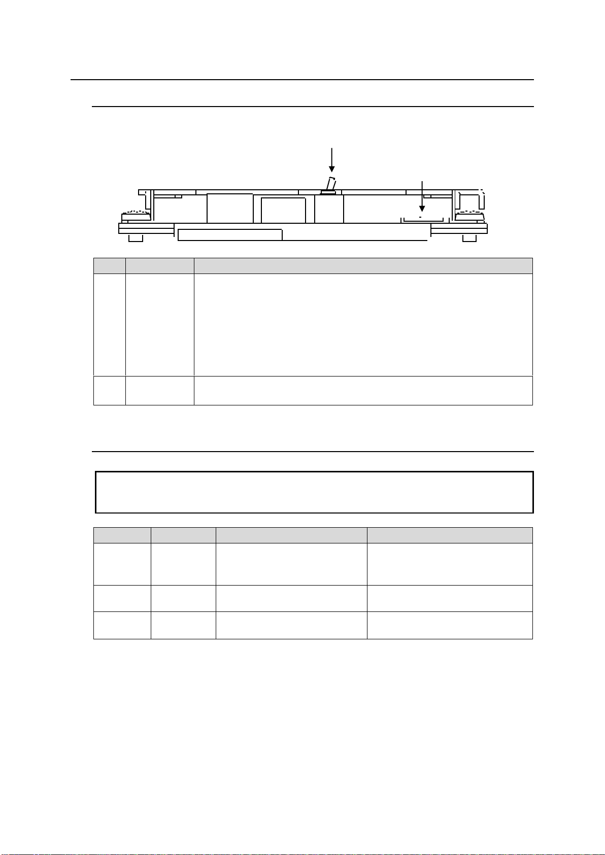
2-1. Front Panel..................................................................................................................................7
2-2. Dipswitch Settings.......................................................................................................................7
2-3. Rear Panel ..................................................................................................................................8
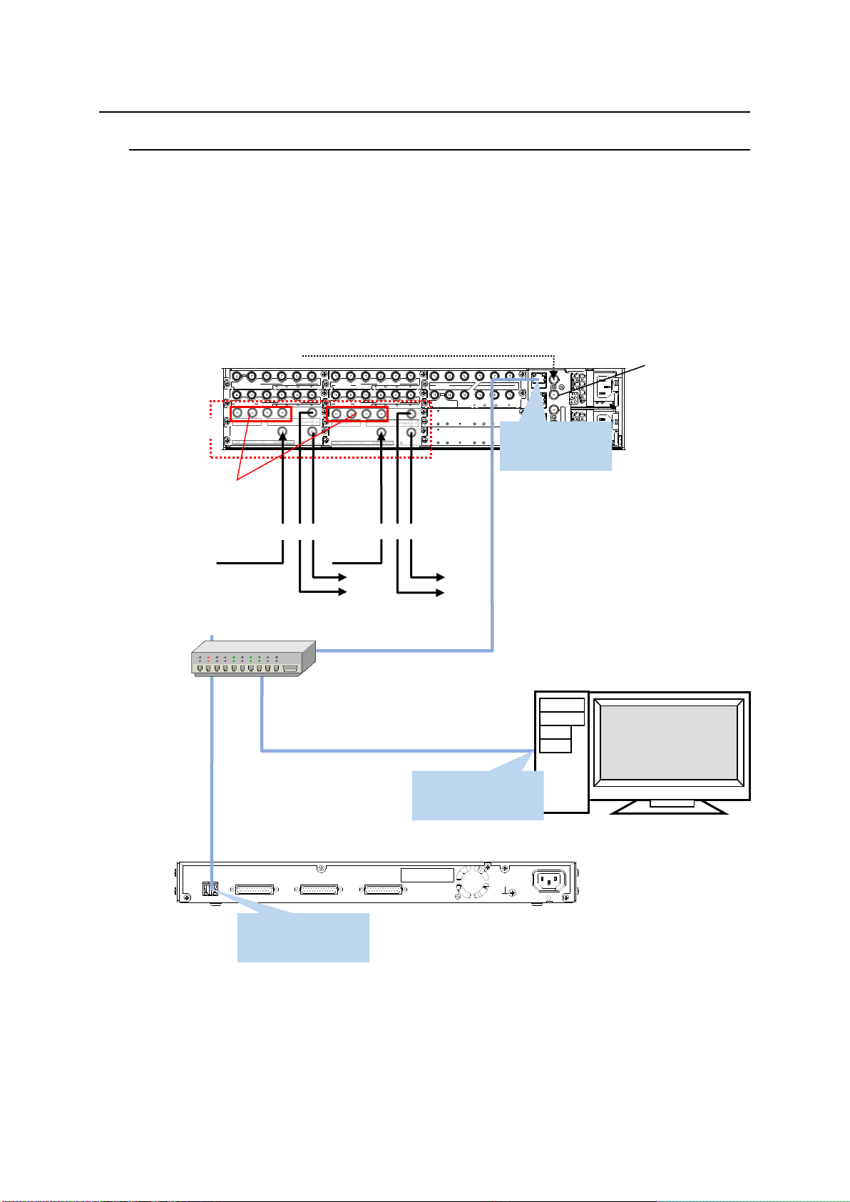
3. Connection ...........................................................................................................................................9
3-1. Basic Configuration.....................................................................................................................9
3-2. Video Input and Output.............................................................................................................10
4. Conversion Table ...............................................................................................................................12
4-1. USF-106UDC-12G....................................................................................................................12
4-1. USF-106DC-12G.......................................................................................................................13
5. USF-106UDC/DC-12G GUI (Windows GUI)......................................................................................14
5-1. Video Tab..................................................................................................................................15
5-1-1. Input Select........................................................................................................................16
5-1-2. Reference Select ...............................................................................................................17
5-1-3. Synchronizer......................................................................................................................17
5-1-4. Converter ...........................................................................................................................18
5-1-5. Color Processor Input Select.............................................................................................23
5-1-6. Color Processor.................................................................................................................23
5-1-6-1. Pre Process Amp/Post Process Amp.........................................................................23
5-1-6-2. Input / Output Gamma / Color ....................................................................................24
5-1-6-3. Dynamic Range Gain .................................................................................................26
5-1-6-4. Differential Color Correct............................................................................................26
5-1-6-5. Knee (RGB) Clip.........................................................................................................27
5-1-6-6. Balance Color Correct................................................................................................27
5-1-6-7. YPbPr Clip..................................................................................................................28
5-1-6-8. Other...........................................................................................................................28
5-1-7. Ancillary .............................................................................................................................29
5-1-8. Output Select.....................................................................................................................31
5-1-9. Video Status.......................................................................................................................31
5-2. Audio Tab..................................................................................................................................32
5-2-1. Input...................................................................................................................................32
5-2-2. Input Delay.........................................................................................................................33
5-2-3. Sampling Rate Converter ..................................................................................................34
5-2-4. Output Mapping .................................................................................................................34
5-2-5. Monosum / Downmix / Test Signal....................................................................................35
5-2-6. Gain ...................................................................................................................................36
5-2-7. Converter Delay.................................................................................................................37
5-2-8. Output ................................................................................................................................37
5-2-9. Audio System.....................................................................................................................38
5-2-10. Input Status / Output Status.............................................................................................38
5-3. Event Tab..................................................................................................................................39
5-3-1. Unsaved Menu Settings.....................................................................................................39
5-4. Status Tab.................................................................................................................................39
6. Web GUI.............................................................................................................................................40
6-1. Module Information ...................................................................................................................40
6-2. Network.....................................................................................................................................40
6-3. Trap...........................................................................................................................................41
6-3-1. SNMP Trap Settings..........................................................................................................41

5
6-3-2. Download MIB File.............................................................................................................41
6-4. Event Data ................................................................................................................................42
6-5. Gamma Data / Gamut Data ......................................................................................................42
7. Command Control ..............................................................................................................................43
7-1. Overview ...................................................................................................................................43
7-2. Communication Method............................................................................................................43
7-3. Slave IP Address Setting ..........................................................................................................43
7-4. Master IP Address Setting ........................................................................................................43
7-5. Setting Command .....................................................................................................................43
7-5-1. Master to Slave Messages ................................................................................................43
7-5-2. Command List - Master to Slave .......................................................................................44
7-5-3. Commands Setting Value..................................................................................................45
7-5-4. Slave Responses to “Master to Slave Messages”.............................................................48
7-5-5. Slave Status Report Messages .........................................................................................49
7-6-1. Checking the Slave Start-up..............................................................................................52
7-6-2. Acquiring the Slave Status.................................................................................................52
7-6-3. Changing the Slave Settings .............................................................................................52
7-6-4. Reporting the Slave Status Change ..................................................................................52
8. SNMP Functions.................................................................................................................................53
8-1. USF-106UDC-12G MIB Information .........................................................................................53
8-2. USF-106DC-12G MIB Information............................................................................................55
9. Specifications and Dimensions ..........................................................................................................57
9-1. Unit Specifications.....................................................................................................................57
9-2. External Dimensions.................................................................................................................58

6
1. Prior to Starting
1-1. Overview
The USF-106UDC/DC-12G module is an up/down converter with FS functions supporting 12G-SDI.
Strongly supports various video conversions with a newly developed color processing circuit that
supports latest Gamut and Dynamic Range.
Audio remapping, audio gain adjustment and audio delay functions are also available.
1-2. Features
Implements a latest SDI interface: 12G-SDI.
Strongly supports HD/4K contents production with a newly developed color processing circuit.
ITU-R BT.2020 (WCG) and ITU-R BT.709 processing and conversion.
Various HDR/ SDR EOTF and OETF reduce differences with external devices.
Custom EOTF / OETF log curves and color space data upload from computer
Dynamic Range conversion for Display light, OOTF (HLG)
Up-/down-/IP-conversions, ranging from SD to HD/4K
3G-SDI Level-A/B and SQD / 2SI conversions
4K conversion between Single-Link 12G-SDI and Quad-Link 3G-SDI (Gearbox)
Robust frame synchronizer with audio and SDI error correction
GUI software (full) and web browser (limited) control and SNMP monitoring
Mounts on USF-212AS and USF-105AS frames

7
2. Panel Descriptions
2-1. Front Panel
USF-106UDC-12G
No.
Name
Description
1
POWER SW
(S2)
Switch used to turn unit power ON / OFF.
Move the switch to the right to turn on the power.
To remove the front module when the frame is powered on, pull out the
module with the switch turned to the left.
To install the front module when the frame is powered on, insert the
module with the switch off (move to left) and turn on (move to right) the
power switch after installation.
(POWER SW not installed on the front module S/N 17610301 and later.)
2
Micro SD
A micro SD card is implemented on the module.
Do not remove the micro SD card.
2-2. Dipswitch Settings
IMPORTANT
Note that dipswitch settings should remain unchanged from factory default settings.
If you have accidentally changed the setting, refer to the table below to return to the factory
default settings.
Dipswitch.
Switch No.
Setting
Remark
DS1
1-3
4
5-8
Off (Do not change)
On (Do not change)
Off (Do not change)
DS2
1-8
Off (Do not change)
(Not installed on the front module
S/N 17610301 and later.)
DS7
1-8
Off (Do not change)
(Not installed on the front module
S/N 17610301 and later.)
2
1
USF-106UDC-12G

8
2-3. Rear Panel
No.
Name
Description
1
12G/3G/HD/SD-SDI IN
Used for 12G/3G/HD/SD-SDI input
2
12G/3G/HD/SD-SDI OUT 1a
Used for 12G/3G/HD/SD-SDI output
12G/3G/HD/SD-SDI OUT 1b
Used for 12G/3G/HD/SD-SDI output
3
3G/HD/SD-SDI IO 2a
Used for 3G/HD/SD-SDI input/output and Link 1 for 4K
Quad Link 3G-SDI.
3G/HD/SD-SDI IO 2b
Used for 3G/HD/SD-SDI input/output and Link 2 for 4K
Quad Link 3G-SDI.
3G/HD/SD-SDI IO 2c
Used for 3G/HD/SD-SDI input/output and Link 3 for 4K
Quad Link 3G-SDI.
3G/HD/SD-SDI IO 2d
Used for 3G/HD/SD-SDI input/output and Link 4 for 4K
Quad Link 3G-SDI.
3
2
1

9
3. Connection
3-1. Basic Configuration
Two USF-106UDC-12G (or USF-106DC-12G) module cards are installed on a USF-212AS frame
in this example. Set input or output for four BNC port on the upper side of the modules. See Sec.3-2.
“Video Input and Output” for details.
The USF frame, the PC and the FA-10RU (optional remote control unit) are connected via LAN.
Install the dedicated Windows GUI software in the PC and setup and operate the modules. (See
Sec.5. “USF-106UDC/DC-12G GUI (Windows GUI)” for details. The PC Web browser allows you to
save/load events (menu settings list) and to import/export Gamma and Gamut settings files. (“See
Sec. 6. “Web GUI.”)
FA-10RU allows you to setup/operate the modules and save/load events. See the “FA-10RU for
USF-106UDC/DC-12G Operation Manual” for details on FA-10RU connection and operation.
VIDEOIN THRU
1 2 1
3G/HD/S DSDI IN
USF-1043FS
USF-1040VEA
1 2
2
3G/HD/S D SDI OUT
VIDEOOUT 3
3
4
4
IN OUT 1/2 3/4 5/6 7/8
-LTC
DIGITAL AUDIOIN
1/2 3/4 5/6 7/8
-LTC
DIGIT AL AUDIOOUT
IN OUT
3G/HD/SDSDI
3G/HD/SDSDI
USF-1013MUX
USF-1013DEMUX
1 2
3G/HD/SDSDI IN
USF-1043DCC
1 2
3G/HD/S D SDI OUT 3 4
5 6 7
VIDEOOUT 1
VIDEOIN THRU
USF-1100VEA
8 9
2 3
10
4LAN 1
LAN 2
GENLOCK 1
GENLOCK 2
LAN A
SER. NO.
AC 100-240V 50 /60Hz IN 1
AC 100-240V 50 /60Hz IN 2
ALARM USF-212
ANALOGAUDIO
SDI IN 1 2 3 4 5
SDI OUT
USF-108ADA
USF-1053DDA
USF-212AS
Rear Panel
Windows GUI
Software
Web browser
AC100-240V 50/60Hz IN
GPI3GPI2GPI1
TO MU
(10/100/1000BASE-T)
Ethernet hub
Reference Signal
4K/HD/SD Video
75Ω Termination
TO MU
192.168.0.100
(255.255.255.0)
LAN port
192.168.0.53
(255.255.255.0)
Setup and operation (Windows GUI Software)
Save/load events (Web browser)
Setup and operation
Save/load events
Selectable
Inputs/outputs
LAN1
192.168.0.10
(255.255.255.0)
FA-10RU (Remote Control Unit option)
USF-106UDC-12G
4K/HD/SD Video

10
3-2. Video Input and Output
If using SDI I/O 2a-2d as input (*1)
(Signals in light blue cells are unavailable on USF-106DC-12G modules.)
Input video
Input port (*2)
SDI OUT 1a, 1b
output video
[Video > Converter] menu settings
HD
SDI IN (SDI 1)
SDI I/O 2a
HD x 2
Format Convert: Follow Input
4K (12G Single) x 2
Format Convert: Manual
Standard: 2160
Frame Rate: 59.94P
Level: Level-A
Division: 2-Sample Interleave
4K
(3G Quad)
SDI I/O 2a-2d
HD x 2
Format Convert: Manual
Standard: 1080
Frame Rate: 59.94i/29.97PsF
4K (12G Single) x 2
Format Convert: Manual
Standard: 2160
Frame Rate: 59.94P
Level: Level-A
Division: 2-Sample Interleave
4K
(12G Single)
SDI IN (SDI 1)
HD x 2
Format Convert: Manual
Standard: 1080
Frame Rate: 59.94i/29.97PsF
4K (12G Single) x 2
Format Convert: Follow Input
(*1) Select Input under [Video > Input Select > SDI 2 Terminal]. (p 16)
(*2) Select an input source under the [Video > Input Select > Source Select]. (p 16)
Input: SDI IN
Output: SDI OUT 1a, 1b
Input: SDI I/O 2a-2d
Output: SDI OUT 1a, 1b
4K (3G Quad) x1 or HD x 1 (2a)
4K or HD
4K or HD
4K or HD
4K or HD
4K or HD

11
If using SDI I/O 2a-2d as output (*3)
(Signals in light blue cells are unavailable on USF-106DC-12G modules.)
Input
video
Input
port
SDI OUT 1a, 1b
output video
SDI I/O 2a-2d
output video
[Video > Converter]
menu settings
HD
SDI IN
(SDI 1)
HD x 2
HD x 4
Format Convert: Follow Input
4K (12G Single)
x 2 (*4)
4K (3G Quad)
x 1
Format Convert: Manual
Standard: 2160
Frame Rate: 59.94P
Level: Level-A or B
Division: 2-Sample Interleave or
Square
4K
(12G
Single)
HD x 2
HD x 4
Format Convert: Manual
Standard: 1080
Frame Rate: 59.94i/29.97PsF
4K (12G Single)
x 2 (*4)
4K (3G Quad)
x 1
Format Convert: Follow Input or
Manual
Standard: 2160
Frame Rate: 59.94P
Level: Level-A or B
Division: 2-Sample Interleave or
Square
(*3) Select Output under [Video > Input Select > SDI 2 Terminal]. (p 16)
(*4) Selecting Level-B or Square displays the black video.
Input: SDI IN
Output: SDI OUT 1a, 1b
SDI I/O 2a-2d
4K (3G Quad) x1 or HD x 4
4K or HD
4K or HD
4K or HD

12
4. Conversion Table
4-1. USF-106UDC-12G
<59.94 Hz>
Output
4K
HD
SD
12G
3G x 4
3G
1.5G
2160/59.94p Level-A 2SI
2160/59.94p Level-A SQD
2160/59.94p Level-A 2SI
2160/59.94p Level-B SQD
2160/59.94p Level-B 2SI
1080/59.94p Level-A
1080/59.94p Level-B
1080/29.97p
1080/23.98p
1080/59.94i (29.97PsF)
1080/23.98PsF
720/59.94p
525/59.94i(SD-SDI)
Input
4K
12G
2160/59.94p Level-A 2SI
3G
x 4
2160/59.94p Level-A SQD
2160/59.94p Level-A 2SI
2160/59.94p Level-B SQD
2160/59.94p Level-B 2SI
HD
3G
1080/59.94p Level-A
1080/59.94p Level-B
1.5G
1080/29.97p
1080/23.98p
1080/59.94i (29.97PsF)
1080/23.98PsF
720/59.94p
SD
525/59.94i (SD-SDI)
<50 Hz>
Output
4K
HD
SD
12G
3G x 4
3G
1.5G
2160/50p Level-A 2SI
2160/50p Level-A SQD
2160/50p Level-A 2SI
2160/50p Level-B SQD
2160/50p Level-B 2SI
1080/50p Level-A
1080/50p Level-B
1080/25p
1080/50i (25PsF)
720/50p
625/50i (SD-SDI)
Input
4K
12G
2160/50p Level-A 2SI
3G
x 4
2160/50p Level-A SQD
2160/50p Level-A 2SI
2160/50p Level-B SQD
2160/50p Level-B 2SI
HD
3G
1080/50p Level-A
1080/50p Level-B
1.5G
1080/25p
1080/50i (25PsF)
720/50p
SD
625/50i (SD-SDI)

13
4-1. USF-106DC-12G
<59.94 Hz>
Output
4K
HD
SD
12G
3G x 4
3G
1.5G
2160/59.94p Level-A 2SI
2160/59.94p Level-A SQD
2160/59.94p Level-A 2SI
2160/59.94p Level-B SQD
2160/59.94p Level-B 2SI
1080/59.94p Level-A
1080/59.94p Level-B
1080/29.97p
1080/23.98p
1080/59.94i (29.97PsF)
1080/23.98PsF
720/59.94p
525/59.94i(SD-SDI)
Input
4K
12G
2160/59.94p Level-A 2SI
3G
x 4
2160/59.94p Level-A SQD
2160/59.94p Level-A 2SI
2160/59.94p Level-B SQD
2160/59.94p Level-B 2SI
HD
3G
1080/59.94p Level-A
1080/59.94p Level-B
1.5G
1080/29.97p
1080/23.98p
1080/59.94i (29.97PsF)
1080/23.98PsF
720/59.94p
SD
525/59.94i (SD-SDI)
<50 Hz>
Output
4K
HD
SD
12G
3G x 4
3G
1.5G
2160/50p Level-A 2SI
2160/50p Level-A SQD
2160/50p Level-A 2SI
2160/50p Level-B SQD
2160/50p Level-B 2SI
1080/50p Level-A
1080/50p Level-B
1080/25p
1080/50i (25PsF)
720/50p
625/50i (SD-SDI)
Input
4K
12G
2160/50p Level-A 2SI
3G
x 4
2160/50p Level-A SQD
2160/50p Level-A 2SI
2160/50p Level-B SQD
2160/50p Level-B 2SI
HD
3G
1080/50p Level-A
1080/50p Level-B
1.5G
1080/25p
1080/50i (25PsF)
720/50p
SD
625/50i (SD-SDI)

14
5. USF-106UDC/DC-12G GUI (Windows GUI)
When starting the USF-106UDC/DC-12G GUI software from the USF-GUI-Launcher (Connection
Manager), the menu screen as shown below appears.
USF-106UDC-12G
USF-106DC-12G
See the USF-GUI-Launcher Operation Manual (separate manual file) for details on how to launch
USF-106UDC/DC -12G GUI using the USF-GUI-Launcher.
Main Menu screen is composed of four tabs: Video, Audio, Event and Status.
Video tab: Shows a block diagram for the video signal processing, from which menu pages are opened.
Audio tab: Shows a block diagram for the audio signal processing, from which menu pages are opened.
Event tab: Allows you to save/load menu settings.
Status tab:Displays the module information.

15
5-1. Video Tab
Selecting the Video tab shows the Video Block diagram.
Click blocks in the processing order to open menus and configure video processing.
USF-106UDC-12G
USF-106DC-12G
Block name
Refer to
Block name
Refer to
Input Select
5-1-1
Color Processor Input Select
5-1-5
Reference Select
5-1-2
Color Processor
5-1-6
Synchronizer
5-1-3
Ancillary
5-1-7
Converter
5-1-4
Output Select
5-1-8
Video Status
5-1-9

16
5-1-1. Input Select
Selecting Input Select in the Video Block diagram opens the following menu screen.
Item
Default
Setting
Description
Format
-
-
Displays the detected input signal format.
If unidentifiable video signal is input, for
example, “Not Supported
(1920 * 1080/59.94i)” appears.
In which case, the input signal is supposed as
the one in parenthesis and proceeded.
Source
Select
SDI 1
SDI 1
SDI 2a-2d
Selects a video signal.
Enabled when SDI 2 Terminal is set to Input.
SDI 2
Terminal
Input
Input
Output
Selects input or output for SDI 2a-2d ports.
Loss
Mode
Black
(Link)
Black(Link)
Black(Separate)
Auto Freeze
Output Mute
Selects the output mode for input signal loss.
Black (Link)(Separate): Outputs a black
video.
Auto Freeze: Freezes and outputs the last
normal video.
Output Mute: Stops outputting video signals.
See note (*2) for 4K Quad Link 3G input.
Format
Detection
Auto
Auto
Manual
Auto: Automatically detects and determines
the input signal format.
Manual: Defines the input signal format using
the following parameters.
The following parameters are effective if Format Convert is set to Manual.
Standard
(*1)
1080
SD
720
1080
2160
Specifies the number of vertical pixels (lines).
Horizontal
Size
1920/3840
1920/3840
The number of horizontal pixels. (Fixed)
Frame
Rate (*1)
59.94i /
29.97PsF
59.94p
50p
29.97p
23.98p
59.94i/29.97PsF
50i/25PsF
23.98PsF
Specifies the frame rate.
Settable frame rates according to the
Standard selection are displayed.
If Standard selection is changed and the
frame rate becomes unaccepted, this field
becomes vacant. In which case, select the
correct frame rate.
Level
Follow
Input
Follow Input
Level A
Level B(Dual
Link)
Specifies the 3G-SDI level.
Displayed if Standard and Frame Rate
combination is 3G-SDI or 12G-SDI.
Follow Input: Uses the same level as input.

17
Division
Follow
Input
Follow Input
Square
2-Sample
Interleave
Specifies the Division method. Displayed if
Standard setting is 2160.
Follow Input: Uses 2SI if 2SI is detected in
input payload identification codes. In
other cases, uses Square.
(*1) Unavailable on USF-106DC-12G
(*2) Loss Mode: When a part of 4K video signal (Quad Link 3G) is lost:
4K input
Loss Mode setting
Output image when a part of image is lost
2-Sample
Interleave
Black(Link)
Compensates the loss and restores the whole input image,
maintaining its appearance.
Black(Separate)
Replaces lost parts with black to restore the whole input
image. The image is displayed with lower luminance.
Auto Freeze
Freezes and outputs the last normal video.
Square
Black(Link)
Outputs a black video.
Black(Separate)
Auto Freeze
Outputs the input video displaying black for the lost part.
5-1-2. Reference Select
Selecting Reference Select in the Video Block diagram opens the following menu screen.
Item
Default
Setting
Description
Reference
Select
Genlock
Genlock
SDI
Free Run
Selects a reference source.
Genlock: Uses a reference signal input to the
USF frame.
SDI: Uses the SDI input.
Free Run: Uses the internal signal generator.
Genlock Select
Genlock 1
Genlock 1
Genlock 2
Selects a reference source from two genlock
signals input to the USF frame.
5-1-3. Synchronizer
Selecting Synchronizer in the Video Block diagram opens the following menu screen.

18
Item
Default
Setting
Description
Mode
Frame
Frame
Line
AVDL
Line(Min)
Selects the reference mode.
Frame: Horizontal and vertical video signal
adjustment referring to genlock signal. Not
necessary for video input and genlock to
sync.
Line: ±1/2H horizontal video signal adjustment
output with 1H delay. Synchronization
necessary for video input and genlock
signal.
AVDL: Horizontal video signal adjustment output
with 1H delay. Synchronization necessary
for video input and genlock signal.
Line(Min): ±1/2H horizontal video signal
adjustment output with minimum delay.
Synchronization necessary for video input
and genlock signal.
Adjust Timing
(Horizontal)
0 Clock
-2750 to 2750
Sets the horizontal offset.
Adjust Timing
(Vertical)
0 Line
-563 to 563
Sets the vertical offset.
Freeze
Enable
Disable
Disable
Enable
Turns freeze On/Off.
Freeze
Mode
Frame
Frame
Odd
Even
Sets the freeze mode.
This setting is ignored if progressive/no signal is
input.
5-1-4. Converter
Selecting Converter in the Video Block diagram opens the following menu screen.
<If Converter is selected:>
Item
Default
Setting
Description
Format
-
-
Specifies the converter output format.
If the specified format is not supported,
“Not Supported” is displayed, indicating
the actual output format in parenthesis.
Format
Convert (*1)
Follow
Input
Follow Input
Manual
Specifies the converter output format.
Follow Input: Converter input signal
format
Manual: Signal format specified below.
The Output Format block parameters are available if Format Convert is set to Manual.

19
Standard (*2)
1080
SD
720
1080
2160(*1)
Specifies the number of vertical pixels
(lines).
Horizontal
1920/
3840
1920/3840
The number of horizontal pixels. (Fixed)
Frame Rate
59.94i/
29.97PsF
59.94p
50p
29.97p
23.98p
59.94i/29.97PsF
50i/25PsF
23.98PsF
Specifies the frame rate.
Settable frame rates according to the
Standard selection are displayed.
If Standard selection is changed and the
frame rate becomes non-compliant, this
field becomes vacant. In which case,
select the correct frame rate.
Level
Level-A
Level-A
Level-B (Dual Link)
Specifies the 3G-SDI Level.
Displayed when Standard and Frame
Rate combination is 3G-SDI or 12G-SDI.
Division (*1)
Square
Square
2-Sample Interleave
Specifies the Division method.
Displays if 2160 is selected for Standard
setting.
Motion
Sense
Adaptive
Adaptive
Field
Frame(Odd 1st)
Frame(Even 1st)
Adaptive: Detects whether there is
motion or no motion in the scene,
and generates an optimal
progressive image.
Field: Generates a progressive image
from one field of an interlaced
image. The created image has no
motion artifacts, but vertical
resolution will be reduced.
Frame(ODD 1st): Generates a
progressive image from two fields
(odd and even) of an interlaced
image. Suitable for progressive
segmented frame input shot in
progressive format.
Frame(EVEN 1st): Generates a
progressive image from two fields
(even and odd) of and interlaced
image.
Anti Alias
Horizontal
0
Off
-7 to +8
Sets the horizontal anti-aliasing for the
output video image.
-7 to +8 (weak to strong)
Set to Off if no anti-aliasing is applied.
Anti Alias
Vertical
0
Off
-7 to +8
Directional
Interpolation
(*1)
Disable
Disable
Enable
Enables/disables Edge Detect Level
setting.
Edge Detect
(*1)
5
0 - 10
Sets Edge Detect Level.
The lower the value, the higher the
detection sensitivity, increasing the
directional interpolation area.
(*1)Unavailable on USF-106DC-12G
(*2)Unavailable on USF-106DC-12G

20
<If Delay is selected:>
Item
Default
Setting(Increments)
Description
Delay
0.0
0.0 - 8.0 (0.5)
Allows you to add a delay from 0.5 to 8.0.
To add no delay, set to “0.0“
Converter
Delay
Frame
Frame
Minimum
Adjustable
Sets the conversion delay mode.
Frame: Applies the delay set under Delay.
Minimum: Applies the minimum delay.
Adjustable: Applies the adjustable delay
based on the Delay setting.
The following settings are available when Converter Delay is set to Adjustable.
Horizontal
0 Clock
-2750 to 2750 Clock
Finely adjusts the horizontal timing.
Vertical
0 Line
-563 to 563 Line
Finely adjusts the vertical timing.
<If Resize is selected:>
Aspect Convert
Item
Default
Setting
Description
SD
Output
(4:3) Full frame
4:3
(4:3) Letterbox 16:9 at top
(4:3) Letterbox 14:9 at top
(4:3) Letterbox greater than 16:9
(4:3) Full frame 4:3
(4:3) Letterbox 16:9 protected
(4:3) Letterbox 14:9
(4:3) Full frame 4:3 alternative 14:9
(4:3) Letterbox 16:9 alternative 14:9
(4:3) Letterbox 16:9 alternative 4:3
(16:9) Letterbox greater than 16:9
(16:9) Full frame 16:9
(16:9) Pillarbox 4:3
(16:9) Full frame protected
(16:9) Pillarbox 14:9
(16:9) Pillarbox 4:3 alternative 14:9
(16:9) Full frame 16:9 alternative 14:9
(16:9) Full frame 16:9 alternative 4:3
Selects the aspect
ratio when
converting HD to SD.
This manual suits for next models
1
Table of contents
Other FOR-A Media Converter manuals

FOR-A
FOR-A UFH-70DCM User manual

FOR-A
FOR-A MV-42HS User manual

FOR-A
FOR-A MV-42HSA User manual

FOR-A
FOR-A VTW-350HS User manual

FOR-A
FOR-A UFM-30UDC User manual

FOR-A
FOR-A FA-9600 User manual

FOR-A
FOR-A USF-212BS User manual

FOR-A
FOR-A DCC-100 User manual

FOR-A
FOR-A FRC-9100 User manual

FOR-A
FOR-A HVS-2000DVE User manual