FOR-A UFH-70DAC User manual

UFH-70DAC
HD/SD D/A Converter
1st Edition - Rev.2
OPERATION
MANUAL


Precautions
Important Safety Warnings
[Power]
Do not place or drop heavy or sharp-edged objects on power cord. A damaged cord
can cause fire or electrical shock hazards. Regularly check power cord for
excessive wear or damage to avoid possible fire / electrical hazards.
[Circuitry Access]
Do not touch any parts / circuitry with a high heat factor.
Capacitors can retain enough electric charge to cause mild to serious shock, even
after power is disconnected. Capacitors associated with the power supply are
especially hazardous. Avoid contact with any capacitors.
Unit should not be operated or stored with cover, panels, and / or casing removed.
Operating unit with circuitry exposed could result in electric shock / fire hazards or
unit malfunction.
[Potential Hazards]
If abnormal smells or noises are noticed coming from the unit, turn power off
immediately and disconnect power cord to avoid potentially hazardous conditions. If
problems similar to above occur, contact authorized service representative before
attempting to again operate unit.
[Consumables]
The consumables used in unit must be replaced periodically. For further details on
which parts are consumables and when they should be replaced, refer to the
specifications at the end of the Operation Manual. Since the service life of the
consumables varies greatly depending on the environment in which they are used,
they should be replaced at an early date. For details on replacing the consumables,
contact your dealer.
Caution
Stop
Hazard
Stop
Caution

Upon Receipt
Unpacking
UFH-70DAC HD/SD D/A converter and their accessories are fully inspected and adjusted prior
to shipment. Operation can be performed immediately upon completing all required connections
and operational settings.
Check your received items against the packing lists below.
ITEM QTY REMARKS
UFH-70DAC 1
Operation Manual 1
Check
Check to ensure no damage has occurred during shipment. If damage has occurred, or items
are missing, inform your supplier immediately.

Table of Contents
1. Prior to Starting...........................................................................................................................1
1-1. Welcome.............................................................................................................................1
1-2. Features..............................................................................................................................1
2. Panel Descriptions......................................................................................................................2
2-1. Front Panel .........................................................................................................................2
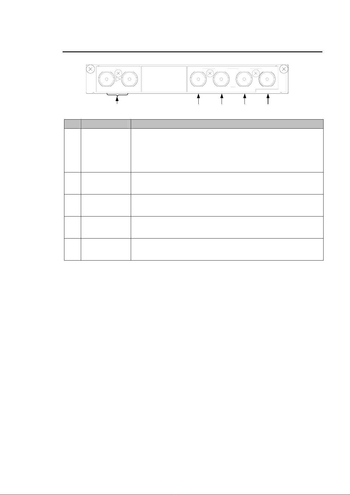
2-2. Rear Panel..........................................................................................................................3
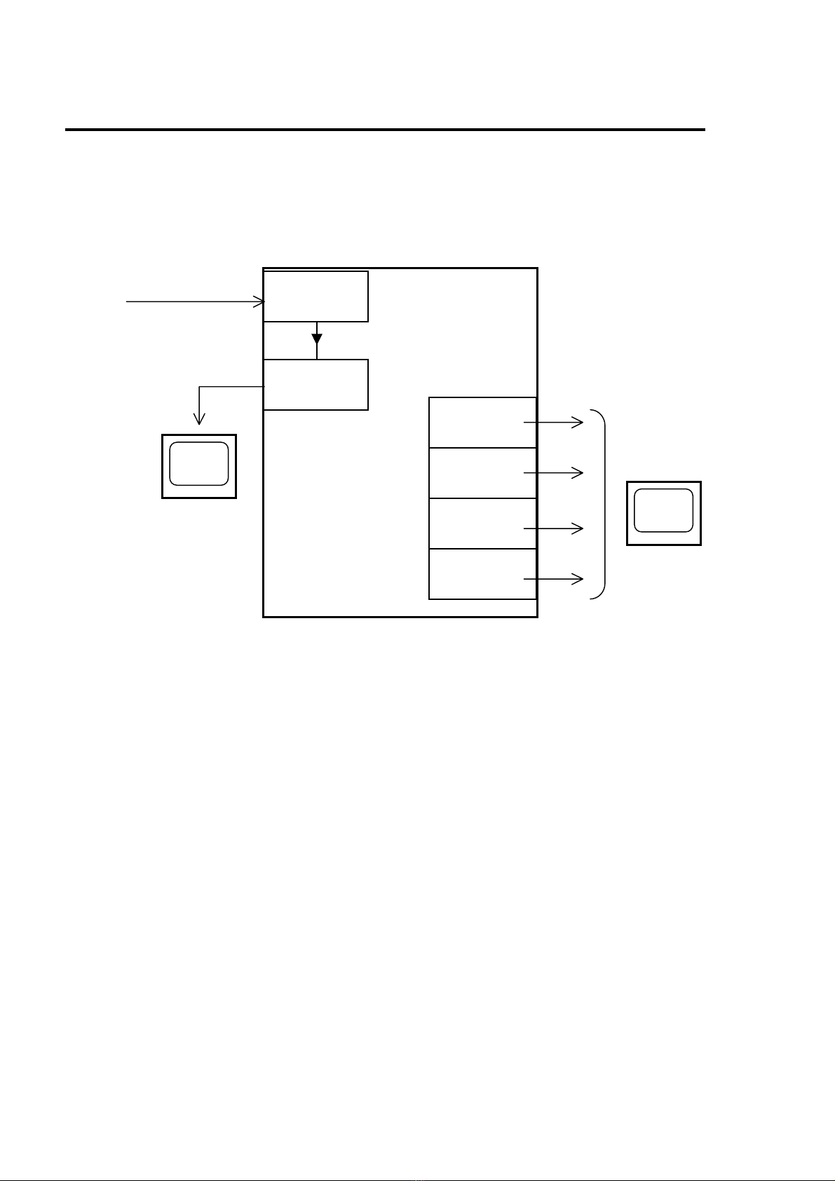
3. Connection..................................................................................................................................4
4. Operations..................................................................................................................................5
4-1. Power On............................................................................................................................5
4-2. Front Panel Controls...........................................................................................................6
4-2-1. UNITY/OPERATE.......................................................................................................6
4-2-2. VIDEO LEVEL ............................................................................................................6
4-2-3. CHROMA LEVEL........................................................................................................7
4-2-4. SETUP/BLACK...........................................................................................................7
4-2-5. CHROMA PHASE.......................................................................................................7
4-3. Dipswitch Setting (FUNCTION)...........................................................................................8
4-3-1. Detailed Setting for Analog Output..............................................................................9
5. Internal Settings........................................................................................................................10
5-1. Dipswitch Settings.............................................................................................................10
6. Specifications and Dimensions .................................................................................................13
6-1. Unit Specifications.............................................................................................................13
6-2. External Dimensions.........................................................................................................14


1
1. Prior to Starting
1-1. Welcome
Congratulations! By purchasing UFH-70DAC HD/SD D/A Converter you have entered the world
of FOR-A and its many innovative products. Thank you for your patronage and we hope you will
turn to FOR-A products again and again to satisfy your video and audio needs.
FOR-A provides a wide range of products, from basic support units to complex system
controllers, which have been increasingly joined by products for computer video based systems.
Whatever your needs, talk to your FOR-A representative. We will do our best to be of continuing
service to you.
1-2. Features
The UFH-70DAC is a module-type D-to-A Converter that can be installed in a UFH frame. It can
convert HD-SDI and SD-SDI signals into analog signals.
Conversion of HD-SDI and SD-SDI signals into analog signals
Selection of analog signal output enabled (YPBPR, GBR, Y/C, composite signals)
Sync output signals for monitoring supported
Process control functions provided (video level, chroma level, chroma phase, setup/black
level)

2
2. Panel Descriptions
2-1. Front Panel
No Name Description Refer to
Lit Power is supplied to the unit.
(1) POWER LED Unlit Power is not supplied to the unit. ―
Lit Input signal is present.
(2) INPUT LED Unlit Input signal is not present. ―
If set to UNITY:
All knobs of (4) VIDEO LEVEL, (5) CHROMA
LEVEL, (6) SETUP/BLACK and (7) CHROMA
PHASE are returned to factory default. (Unity
setting)
(3) UNITY / OPERATE
switch If set to OPERATE:
All knobs of (4) VIDEO LEVEL, (5) CHROMA
LEVEL, (6) SETUP/BLACK and (7) CHROMA
PHASE are enabled.
4-2-1
(4) VIDEO LEVEL Used to adjust video level. 4-2-2
(5) CHROMA LEVEL Used to adjust chroma level. 4-2-3
(6) SETUP / BLACK Used to adjust setup level. 4-2-4
(7) CHROMA PHASE Used to adjust chroma phase. 4-2-5
(8) FUNCTION Used to select output signal and operation mode. 4-3
14253678
POWERINPUT VI DEO LEVEL SETUP/ BLACK CH ROMA PHASECHROMA LEVEL
PROCESS CONTROL FUNCTION
UNITY
OP-
ERATE
UFH-70DAC
UFH-70DAC
(
1
)
(
2
)
(
3
)
(
4
)
(
5
)
(
6
)
(
7
)
(
8
)

3
2-2. Rear Panel
No Name Description
(1) HD/SD-SDI IN
HD/SD-SDI
OUT
The left connector is used to input a serial digital component signal
(HD/SD-SDI).
The right connector is active through output of HD/SD-SDI IN. The
jitter in the active-through output depends on how much jitter is
included in the input video. This card module has no jitter-reducing
function.
(2) Y / G / C1
(HD/SD,
ANALOG OUT)
The signal input from (1) is D/A converted and output from (2), (3),
(4), and (5). The Y (HD/SD component), G (RGB component) or
composite signal can be output from this connector (2).
(3) PB/ B / C2
(HD/SD,
ANALOG OUT)
The signal input from (1) is D/A converted and output from (2), (3),
(4), and (5). The PB(HD/SD component), B (RGB component),
Y(Y/C) or composite signal can be output from this connector (3).
(4) PR/ R / C3
(HD/SD,
ANALOG OUT)
The signal input from (1) is D/A converted and output from (2), (3),
(4), and (5). The PR(HD/SD component), R (RGB component), C
(Y/C) or composite signal can be output from this connector (4).
(5) SYNC / C4
(HD/SD,
ANALOG OUT)
The signal input from (1) is D/A converted and output from (2), (3),
(4), and (5). The composite, bi-level sync, or tri-level sync signal can
be output from this connector (5).
The FUNCTION (see previous page) on the front panel enables you to select the type of signal
output from HD/SD ANALOG OUT (see also section 4-3).
SYNC/C4P /R/C3P /B/C2Y/G/C1
Y
BR
C
HD/SD-SDI IN HD/SD ANALOG OUT UFH-70DAC
(
1
)
(
2
)
(
3
)
(
4
)
(
5
)

4
3. Connection
Connect the unit to other equipment in the total system as shown in the figure below.
Note that before installing the UFH-70 DAC into the System Frame, you should thoroughly read the
operation manual for the System Frame where you will be installing. Turn off the System Frame
and other equipment before connection.
UFH-70DAC
HD/SD-SDI IN
HD/SD-SDI OUT
ANALOG OUT
Y / G / C1
ANALOG OUT
PB/ B / C2
ANALOG OUT
PR/ R / C3
ANALOG OUT
SYNC / C4
HD-SDI signal
or
SD-SDI signal
HD/SD-SDI Monitor
or other device
UFH System Frame
Analog Monito
r
or other device

5
4. Operations
4-1. Power On
1) Loosen the two knob screws on the front panel face of the system frame, and then grasp the
knob screws to pull them out.
2) Turn the power switch(es) ON.
ALARMGENLOCK FAN2TEMP
1
POWER GENLOCK
12FAN
ALARM
TEMP DCPOW
1DCPOW2
POWER
UFH-112A
SYSTEM FRAME
21
+-
POWER GENLOCK FAN V.ADJ
DC POWER
V.CHK
POWER
TEMP
21
DC POWERTEMPFANGENLOCK
POWER
POWER
SER.NO.
(PUSH)LOCK
OPERATE
8765432172134568
UFH-70DEMUX
UFH-70DEMUX
(PUSH)LO CK
OPERATE
8765432172134568
UFH-70MUX
UFH-70MUX
14253678
POWERIN PU T VIDEO LEVEL SETUP/BLACK CHR OMA PHASECHROMALEVEL
PROCESS CONTROL FUNCTION
UNITY
OP-
ERATE
UFH-70DAC
UFH-70DAC

6
4-2. Front Panel Controls
4-2-1. UNITY/OPERATE
Set the switch to the upper or lower positions to switch between UNITY and OPERATE.
Switch and Controls Description
Upper
position
(UNITY)
All process control settings are
disabled and return to the
default settings.
All four LEDs below the
controls illuminate.
Lower
position
(OPERATE)
The following process control
settings are enabled.
VIDEO LEVEL
CHROMA LEVEL
SETUP/BLACK
CHROMA PHASE
4-2-2. VIDEO LEVEL
Switch and Controls Description
UNITY/OPERATE:
Lower position
(OPERATE)
Turn the VIDEO
LEVEL control to
adjust.
Adjusts video level.
Setting range: -3dB to +3dB
When the control is set to the
center position (unity setting),
the LED below the control
illuminates.
PROCESS CONTROL
VIDEO
LEVEL
UNITY
OPERATE
LEVEL SETUP/
BLACK PHASE
CHROMACHROMA
PROCESS CONTROL
VIDEO
LEVEL
UNITY
OPERATE
LEVEL SETUP/
BLACK PHASE
CHROMACHROMA
PROCESS CONTROL
VIDEO
LEVEL
UNITY
OPERATE
LEVEL SETUP/
BLACK PHASE
CHROMACHROMA

7
4-2-3. CHROMA LEVEL
Switch and Controls Description
UNITY/OPERATE:
Lower position
(OPERATE)
Turn the CHROMA
LEVEL control to
adjust.
Adjusts chroma level.
Chroma Level controls how
much color (saturation) is
increased or decreased.
Setting range: -3dB to +3dB
When the control is set to the
center position (unity setting),
the LED below the control
illuminates.
4-2-4. SETUP/BLACK
Switch and Controls Description
UNITY/OPERATE:
Lower position
(OPERATE)
Turn the SETUP/
BLACK control to
adjust.
Adjusts setup black level.
Turning the control clockwise
brightens the setup black.
Setting range:
-15 IRE to +15 IRE
When the control is set to the
center position (unity setting),
the LED below the control
illuminates.
4-2-5. CHROMA PHASE
Switch and Controls Description
UNITY/OPERATE:
Lower position
(OPERATE)
Turn the CHROMA
PHASE control to
adjust.
Adjusts chroma phase.
Setting range: -30°to +30°
When the control is set to the
center position (unity setting),
the LED below the control
illuminates.
PROCESS CONTROL
VIDEO
LEVEL
UNITY
OPERATE
LEVEL SETUP/
BLACK PHASE
CHROMACHROMA
PROCESS CONTROL
VIDEO
LEVEL
UNITY
OPERATE
LEVEL SETUP/
BLACK PHASE
CHROMACHROMA
PROCESS CONTROL
VIDEO
LEVEL
UNITY
OPERATE
LEVEL SETUP/
BLACK PHASE
CHROMACHROMA

8
4-3. Dipswitch Setting (FUNCTION)
Setting
Pin No. Item OFF (Up) ON (Down) Factory
Set
1=OFF, 2=OFF: YPBPR
SW2-1 1=ON, 2=OFF: GBR OFF
1=OFF, 2=ON: Y/C
SW2-2 Analog output selection 1
1=ON, 2=ON: Composite OFF
SW2-3 Analog output selection 2 Composite SYNC OFF
SW2-4 ―――
SW2-5 Output selection when
signal not present BLACK NO SIGNAL OFF
SW2-6 Internal test signal OFF ON OFF
SW2-7 ―――
SW2-8 ―――
Analog output selection 1 ( SW2-1, 2 )
Selects an output signal format for the connectors Y/G/C1, PB/B/C2 and PR/R/C3 (see
section 4-3-1). Only YPBPRor GBR can be selected if an HD-SDI signal is input to the unit.
Analog output selection 2 ( SW2-3 )
Selects an output signal format for the SYNC/C4 connector.
Only SYNC can be selected if an HD-SDI signal is input to the unit (see section 4-3-1).
Output selection when signal not present ( SW2-5 )
Selects black video or no video output from ANALOG OUT when input signal is not present.
No signal will be output from HD/SD-SDI OUT (active through) regardless of this setting
when input signal is not present.
Internal test signal ( SW2-6 )
Outputs a test signal (Color Bar or Cross Hatch) from ANALOG OUT if set to ON. However,
the test signal is not output from HD/SD-SDI OUT (active through). Use dipswitch SW6-8 to
select test signal between Color Bar and Cross Hatch (see section 5-1).
The test signal can be output in synced with the input signal if an HD/SD-SDI signal is input to
the unit. Select the test signal format manually by the SW6 switch setting if any signal is not
input to the unit. Note that the unit may not output test signals correctly if manually selected
format does not match with the input signal. If set to Auto Detection and any signal is not input
to the unit, the last used signal format is selected for the test signal (see section 5-1).
Proc Amp controls cannot be performed during test signal output.

9
4-3-1. Detailed Setting for Analog Output
Analog output signals can be set manually as shown in the table below by the dipswitches
SW2-1, SW2-2, and SW2-3.
Switch Setting Analog Output Signal
SDI
Input SW
2-1 SW
2-2 SW
2-3 Y/G/C1 PB/B/C2 PR/R/C3 SYNC/C4
OFF OFF OFF Y (SD) B-Y (SD) R-Y (SD) Composite
OFF OFF ON Y (SD) B-Y (SD) R-Y (SD) Bi-level
Sync
ON OFF OFF G (SD) B (SD) R (SD) Composite
ON OFF ON G (SD) B (SD) R (SD) Bi-level
Sync
OFF ON OFF Composite Y (SD) C (SD) Composite
OFF ON ON B.B. Y (SD) C (SD) Bi-level
Sync
SD-SDI
ON ON ―Composite Composite Composite Composite
OFF OFF ON Y (HD) PB(HD) PR(HD) Tri-level
Sync
HD-SDI ON OFF ON G (HD) B (HD) R (HD) Tri-level
Sync

10
SW7SW5
Front moduleRear module
SW6
5. Internal Settings
5-1. Dipswitch Settings
The following settings can be made at the dipswitches (SW5, SW6 and SW7) on the front
module of the UFH-70DAC.
SW5 Setting Setting
Pin No. Item OFF ON Factory Set
SW5-1 ―――OFF
SW5-2 ―――OFF
SW5-3 ―――OFF
SW5-4 ―――OFF
SW5-5 ―――OFF
SW5-6 ―――OFF
SW5-7 ―――OFF
SW5-8 ―――OFF

11
SW6 Setting Setting
Pin No. Item OFF ON Factory
Set
SW6-1 OFF
SW6-2 OFF
SW6-3 OFF
SW6-4 OFF
SW6-5
Input signal format (See below.)
OFF
SW6-6 Setup 0 IRE 7.5 IRE OFF
SW6-7 Component signal level BETACAM SMPTE OFF
SW6-8 Test signal selection Color Bar Cross Hatch OFF
Input signal format ( SW6-1 to SW6-5 )
Selects the input signal format. To use the input signal auto detection, set all switches
(SW6-1 to SW6-5) to Off. Otherwise, set manually following the table below.
Auto/
Manual Input signal
format SW6-1 SW6-2 SW6-3 SW6-4 SW6-5
Auto
Detection ―OFF OFF OFF OFF OFF
Manual Set 525/59.94 (NTSC) ON OFF OFF OFF OFF
Manual Set 625/50(PAL) OFF ON OFF OFF OFF
Manual Set 720/60p ON ON OFF OFF OFF
Manual Set 720/59.94p OFF OFF ON OFF OFF
Manual Set 720/50p ON OFF ON OFF OFF
Manual Set 1035/60i OFF OFF OFF ON OFF
Manual Set 1035/59.94i ON OFF OFF ON OFF
Manual Set 1080/60i OFF ON OFF ON OFF
Manual Set 1080/59.94i ON ON OFF ON OFF
Manual Set 1080/50i OFF OFF ON ON OFF
NOTE
Set the input signal format manually if auto format detection is not properly carried out.
Setup ( SW6-6 )
Selects the black setup between 0 or 7.5 IRE when SDTV (NTSC) analog signal (Y/B-Y/R-Y,
Y/C or Composite) is selected for output.
Component signal level ( SW6-7 )
Selects the component signal level between BETACAM or SMPTE when Y/B-Y/R-Y of SDTV
(NTSC) is selected for analog output.
Test signal selection ( SW6-8 )
Select an internally generated test signal between Color Bar and Cross Hatch.

12
SW7 Setting Setting
Pin No. Item OFF ON Factory
Set
SW7-1 ―――OFF
SW7-2 ―――OFF
SW7-3 Mono/Color output Color Mono OFF
SW7-4 ―――OFF
SW7-5 ―――OFF
SW7-6 ―――OFF
SW7-7 GBR output w/ sync
or w/o sync ON OFF OFF
SW7-8 ―――OFF
Mono/Color output ( SW7-3 )
Selects color or monochrome (B/W) output.
GBR output with sync or without sync ( SW7-7 )
Selects GBR with sync or GBR without sync. Set to Off if using GBR with sync (factory
default).

13
6. Specifications and Dimensions
6-1. Unit Specifications
HD-SDI 1080/59.94i, 720/59.94p, 1080/50i, 720/50p, 1080/60i, 720/60p,
1035/59.94i, 1035/60i
Standards
SD-SDI 525/59.94, 625/50
Video Inputs HD/SD-SDI 1.485G / 270Mbps, 75Ω, BNCx1
HD/SD-SDI 1.485G / 270Mbps, 75Ω, BNCx1 (active through)
75Ω, BNCx4 (refer to below)
- YPBPR(HD/SD) Y:1.0Vp-p, PBPR or B-Y/R-Y: 0.7Vp-p
-GBR(HD/SD) 1.0Vp-p (with sync)
-Y/C Y: 1.0Vp-p, C: 0.682Vp-p
-Composite 1.0Vp-p
-Bi-level sync 0.3Vp-p
Video Outputs Analog
-Tri-level sync 0.6Vp-p
Quantization Y: 10-bit, C: 10-bit
I/O Delay HD SDI: approx. 500ns
SD SDI: approx. 3µs
HD-SDI Y: 74.25/1.001MHz, C: 37.125/1.001MHzSampling Frequency SD-SD Y:13.5MHz, C: 6.75MHz
Video Level Over ±3dB
Chroma Level Over ±3dB
Hue ±30°
Process Control
Setup / Black Level ±15IRE
Temperature 10°C - 40°C
Humidity 30% - 90% (no condensation)
Power Supply from UFH Frame, +24VDC
Consumption Approx. 6.5VA (6.5W)
Weight Approx. 1 kg
Front module 138.5 (W) x 400 (D) mm
Dimensions Rear module 141 (W) x 101 (D) mm
Required Slot 1 slot
Consumables No Consumables

14
6-2. External Dimensions
(All dimensions in mm.)
14253678
SYNC /C 4P / R/C 3P /B/C2Y/ G/C 1
Y
BR
C
(400)
379.5
(101)
87.820
141
HD/SD -SD I I N HD /SD A N ALOG OUT
POWERINPUT
VIDEOLEVELSETUP/BLACKCHROMA PHASECHROMALEVEL
PROCESSCONTROL FUNCTION
UNITY
OP-
ERATE
UFH-70DAC
UFH-70DAC
UFH-70DAC
Table of contents
Other FOR-A Media Converter manuals

FOR-A
FOR-A USF-212BS User manual

FOR-A
FOR-A VTW-350HS User manual

FOR-A
FOR-A FA-9600 User manual

FOR-A
FOR-A HVS-2000DVE User manual

FOR-A
FOR-A DCC-100 User manual

FOR-A
FOR-A UFH-70DCM User manual

FOR-A
FOR-A UFM-30UDC User manual

FOR-A
FOR-A FRC-9100 User manual

FOR-A
FOR-A MV-42HSA User manual

FOR-A
FOR-A USF-106UDC-12G User manual
Popular Media Converter manuals by other brands

StarTech.com
StarTech.com ET91000SM40 Specifications

StarTech.com
StarTech.com ET90110SC Instruction guide

Xylem
Xylem Lowara ResiBoost MMW Series Installation, operation and maintenance manual

Axel
Axel Streamer RX user guide

Wavetronix
Wavetronix Click 304 quick start guide

TRENDnet
TRENDnet TFC-110S60 Specifications