FOR-A UFM-30UDC User manual

UFM-30UDC
Digital Up/Down/Cross Converter
2nd Edition
OPERATION
MANUAL

Edition Revision History
Edit. Rev. Ver. Date Description Where
1 - 1.02 2010/01/19
2 - 2.02 2010/06/10 UFM-30CTL control supported

Precautions
Important Safety Warnings
[Power]
Do not place or drop heavyor sharp-edged objects on power cord. A damaged cord
can cause fire or electrical shock hazards.
Regularly check power cord for
excessive wear or damage to avoid possible fire / electrical hazards.
[Circuitry Access]
Do not touch any parts / circuitry with a high heat factor.
Capacitors can retain enough electric charge to cause mild to serious shock, even
after power is disconnected. Capacitors associated with the power supply are
especially hazardous. Avoid contact with any capacitors.
Unit should not be operated or stored with cover, panels, and / or casing removed.
Operating unit with circuitry exposed could result in electric shock / fire hazards or
unit malfunction.
[Potential Hazards]
If abnormal sme
lls or noises are noticed coming from the unit, turn power off
immediately and disconnect power cord to avoid potentially hazardous conditions. If
problems similar to above occur, contact authorized service representative before
attempting to again operate unit.
[Consumables]
The consumables used in unit must be replaced periodically. For further details on
which parts are consumables and when they should be replaced, refer to the
specifications at the end of the Operation Manual. Since the service life of the
consumables varies greatly depending on the environment in which they are used,
they should be replaced at an early date. For details on replacing the consumables,
contact your dealer.
Caution
Stop
Hazard
Stop
Caution

Upon Receipt
Unpacking
UFM-30UDC module units and their accessories are fully inspected and adjusted prior to
shipment. Operation can be performed immediately upon completing all required connections
and operational settings.
Check your received items against the packing lists below.
ITEM QTY REMARKS
UFM-30UDC 1 set Front module x1
Rear module x1
Operation Manual 1 (This manual)
IMPORTANT
The UFM-30CTL with the following versions can control UFM-30UDC modules.
-Web & Control PORT Version 2.00 or higher
-SNMP PORT Version 1.21 or higher
-FPGAVersion 1.00 or higher
See the UFM-30CTL manual for how to control UFM-30UDC from a web browser.
Check
Check to ensure no damage has occurred during shipment. If damage has occurred, or items
are missing, inform your supplier immediately.

Table of Contents
1. Prior to Starting........................................................................................................................... 1
1-1. Welcome.............................................................................................................................. 1
1-2. Features .............................................................................................................................. 1
2. Panel Descriptions...................................................................................................................... 2
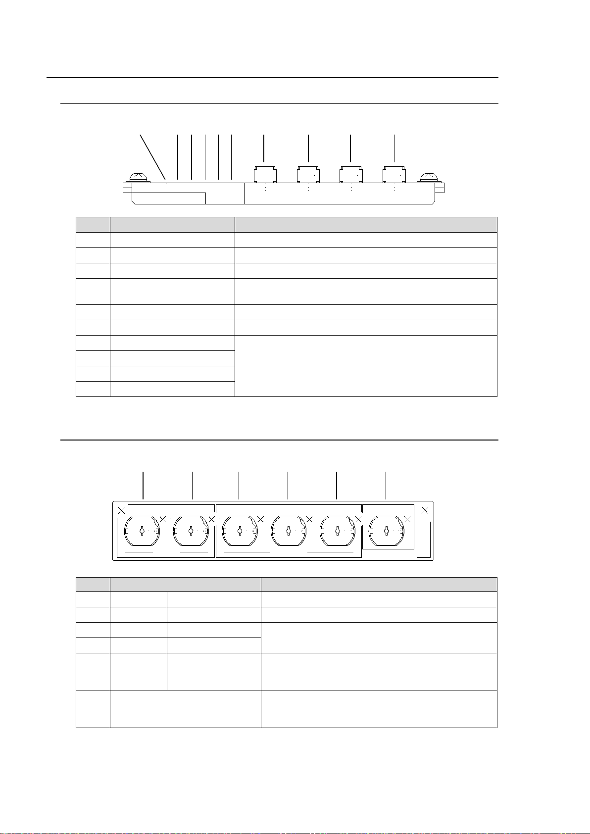
2-1. Front Panel.......................................................................................................................... 2
2-2. Rear Panel........................................................................................................................... 2
3. Connection and Setup................................................................................................................ 3
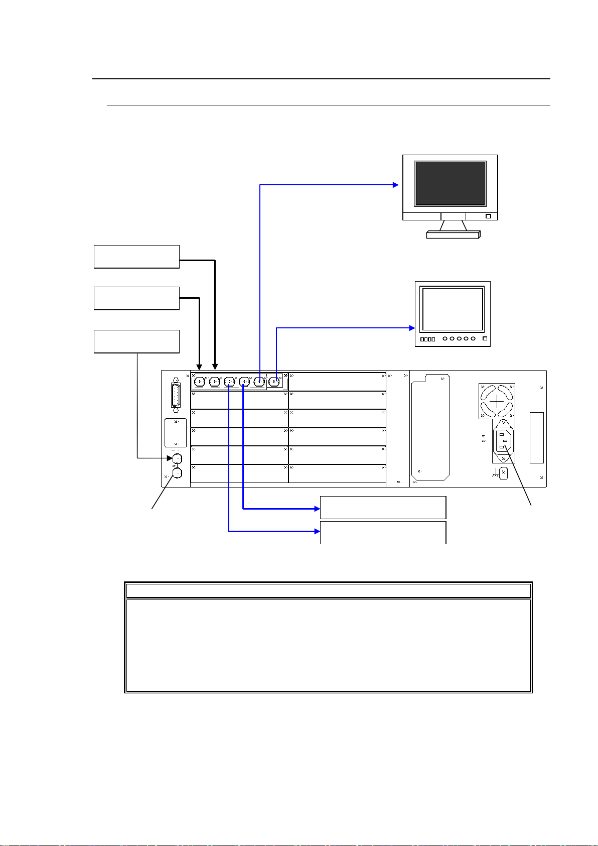
3-1. Connection .......................................................................................................................... 3
3-2. Note on Composite Input .................................................................................................... 4
3-3. Composite Monitor Setup.................................................................................................... 4
3-4. SDI Monitor Setup............................................................................................................... 4
4. Operations.................................................................................................................................. 5
4-1. Power On............................................................................................................................. 5
4-2. Menu Operation................................................................................................................... 5
4-2-1. Displaying Menu........................................................................................................... 5
4-2-2. Displaying Status ......................................................................................................... 6
4-2-3. Changing Value............................................................................................................ 7
4-2-4. Resetting All Items in the Menu................................................................................... 9
5. Conversion Examples............................................................................................................... 10
5-1. SD to HD (without Genlock).............................................................................................. 10
5-2. SD to HD (with Genlock)................................................................................................... 11
5-3. HD to SD (with Genlock)................................................................................................... 12
5-4. Composite to SD (without Genlock).................................................................................. 13
5-5. Composite to HD (with Genlock)....................................................................................... 14
5-6. SD to SD (Aspect Conversion).......................................................................................... 15
5-7. Other Setting ..................................................................................................................... 16
5-8. Embedded Audio............................................................................................................... 17
5-9. Test Signal......................................................................................................................... 17
6. Aspect Ratio Scaling ................................................................................................................ 18
6-1. Up-conversion (SD to HD) ................................................................................................ 19
6-2. Down-conversion (HD to SD)............................................................................................ 20
6-3. SD to SD conversion – 4:3 Output.................................................................................... 21
6-4. SD to SD conversion – 16:9 Anamorphic Output ............................................................. 22
6-5. SD to SD conversion - 16:9 Letter Box Output................................................................. 23
7. Menu List.................................................................................................................................. 24
7-1. Status Menu (Display only)............................................................................................... 24
7-2. Input menu......................................................................................................................... 24
7-3. Output menu...................................................................................................................... 25
7-4. Scaling menu..................................................................................................................... 27
8. Specifications and Dimensions ................................................................................................ 28
8-1. Specifications.................................................................................................................... 28
8-2. External Dimensions ......................................................................................................... 30


1
1. Prior to Starting
1-1. Welcome
Congratulations! By purchasing UFM-30UDC Up/Down/Cross Converter you have entered the
world of FOR-A and its many innovative products. Thank you for your patronage and we hope
you will turn to FOR-A products again and again to satisfy your video and audio needs.
FOR-A provides a wide range of products, from basic support units to complex system
controllers,which have been increasingly joined by products for computer video based systems.
Whatever your needs, talk to your FOR-A representative.We will do our best to be of continuing
service to you.
The UFM-30UDC is a plug-in module to be mounted on the UFM frame. It is an up-, down- and
cross-converter of 3G/HD/SD-SDI, which is involved with the application of the latest digital
technology. It standardly supports 3G-SDI, a next-generation format, and allows you to convert
signals between various video formats.
Available Combinations of Input and Output Format
Input signal format Output signal format
3G-SDI 1080/59.94p Level A
1080/59.94p Level B 3G-SDI 1080/59.94p Level A
1080/59.94p Level B
HD-SDI 1080/59.94i
720/59.94p HD-SDI 1080/59.94i
720/59.94p
SD-SDI 525/59.94i SD-SDI 525/59.94i
Composite NTSC
Input signal Output signal
3G-SDI 1080/50p Level A
1080/50p Level B 3G-SDI 1080/50p Level A
1080/50p Level B
HD-SDI 1080/50i
720/50p HD-SDI 1080/50i
720/50p
SD-SDI 625/50i SD-SDI 625/50i
Composite PAL
The frame rate conversion between 59.94Hz and 50Hz is not possible.
1-2. Features
3G/HD/SD-SDI up/down/cross converter.Analog composite input also available.
3G/HD/SD-SDI: 1-input/2-output. Composite: 1-input
3G-SDI Level A and Level B support (*1)
5 aspect ratio selection (4:3,13:9, 14:9, 16:9 and SQUEEZE)
Embedded audio pass-through: 8 ch (Group1 and 2)
SDI Preview Out: input or output monitoring selectable
Analog Composite Out: SD image monitoring and menu operation
Menu display onAnalog Composite Out using OSD (On Screen Display)
Built-in frame synchronizer (Black Burst and Tri-level Sync)(*2)
Proc Amp
Motion adaptive filter and enhancer
Closed caption pass-through
Control and monitor with a standard web browser via Ethernet using the WEB control
function of UFM-30CTL.
(*1) For Level B, only dual link features from SMPTE 372M are supported.
(*2) With BB input, UFM-30UDC gen-locks signals horizontally (H lock), but does not correct
subcarrier phase shifts.

2
2. Panel Descriptions
2-1. Front Panel
No. Name Description
(1) POWER LED LED lights up when power is supplied to the module.
(2) CPU/COMMS LED Not used
(3) IN OK LED LED lights up when an input signal is present.
(4) REF OK LED LED lights up when agenlock signalis input to the UFM
frame.
(5) HD OUT LED LED lights up when outputting HD-SDI signals.
(6) 3Gb/s OUT LED LED lights up when outputting 3G-SDI signals.
(7) MENU OSD button These buttons are used for menu operation.
(See section 4-2. "Menu Operation")
(8) SELECT button
(9) UP button
(10) DOWN button
2-2. Rear Panel
No. Name Description
(1) INPUT COMPOSITE Used for Composite signal input.
(2) INPUT 3G/HD/SD-SDI Used for 3G/HD/SD-SDI signal input.
(3) OUTPUT 3G/HD/SD-SDI 1 Used for 3G/HD/SD-SDI signal output.
(4) OUTPUT 3G/HD/SD-SDI 2
(5) OUTPUT SDI MONITOR Used for previewing output video (SDI signal).
Previewing input signal is also possible. See
section 3-4. "SDI Monitor Setup" for details.
(6) OSD OUT Used for monitoring output video and displaying
menu. See section 3-3. "Composite Monitor
Setup."
MENU SELECT UP DOWN
OSD
UFM-30UDC
CPU/
COMMS IN
OK REF
OK HD
OUT 3.0Gb/s
OUT
POWER
(1)
(2)(3)(4)(5)(6)
(7)
(8)
(9)
(10)
(1)
UFM-30UDC
OUTPUTINPUT
COMPOSITE 3G/HD/SD-SDI 3G/HD/SD-SDI 1 3G/HD/SD-SDI 2 SDI MONITOR OSD OUT
(2)
(3)
(4)
(5)
(6)

3
3. Connection and Setup
3-1. Connection
Turn off the power of all devices in the system before connection.
IMPORTANT
Although two video inputs are provided, only one input can be processed through the
UFM-30UDC.
The processed video is sim
ultaneously sent to four ports; SDI1, SDI2, SDI MONITOR
and OSD OUT.
With BB input, the UFM-30UDC gen-
locks signals horizontally (H lock), but does not
correct subcarrier phase shifts. (See section 7-3. "Output menu .")
RATINGLABEL
GENLOCK IN ALARM
AC100-240V ~ 50/60Hz IN
FAN
ALM
UFM-30UDC
OUTPUTINPUT
COMPOSITE 3G/HD/SD-SDI 3G/HD/SD-SDI 1 3G/ HD/SD-SDI 2 SDI MONITOR OSD OUT
UF-112 Rear Panel
Power Source
75 ohm termination required
if not looped through.
NTSC
(
PAL
)
Monitor
for menu display
SDI monitor for
previewing video
Processed signal (SDI2)
Processed signal (SDI1)
SDI video
Composite video
Genlock signal

4
3-2. Note on Composite Input
When the NTSC composite signal is input, the setup level should be set manually in the menu.
The factory default setting is Off (0IRE). See section 4-2. "Menu Operation" for how to change
menu items.
NTSC setup level Menu item Setting
0IRE (used in Japan) Input - NTSC setup Off (default setting)
7.5IRE (used in USA) Input - NTSC setup On
3-3. Composite Monitor Setup
Prepare an NTSC or PAL monitor for displaying menu. Select NTSC or PAL according to the
input signal that you want to process.
Monitor Input signal
NTSC monitor Video signals at 59.94Hz frame rate:
(NTSC, 525/59.94i, 720/59.94p, 1080/59.94i and 1080/59.94p)
PAL monitor Video signals at 50Hz frame rate:
(PAL, 625/50i, 720/50p, 1080/50i and 1080/50p)
Connect the monitor to the OSD OUT on the UFM-30UDC rear panel. If NTSC monitor is used,
set the setup level. The default setting in the UFM-30UDC is 7.5 IRE.
If using an NTSC Monitor with 0 IRE Setup (used in Japan)
Change the OSD OUT item in the Output menu from PAL/NTSC to PAL/NTSC-J.
See section 4-2. "Menu Operation" for how to change menu items.
Monitoring Input Image or Output Image
The output image is also displayed on the Composite monitor when SD signal is selected for
output. However, in some cases, it isn't displayed properly because the OSD OUT images
are not phase adjusted by the reference signal.
If the Monitor item in the Output menu is set to Input, the input image is also displayed on
the Composite monitor only when inputting a composite or an SD-SDI signal. (See "3-4. SDI
Monitor Setup" below)
3-4. SDI Monitor Setup
Prepare an SDI monitor for previewing images. The SDI monitor is connected to the SDI
MONITOR OUT on the UFM-30UDC rear panel. Both input and output images can be
previewed on the SDI monitor. The output image is displayed in the factory default setting.
To Monitor Input Image Before Processing
Change the Monitor item in the Output menu to Input. The converted SD-SDI image is sent
to the SDI monitorout when inputting a composite image. See section 4-2. "Menu Operation"
for how to change menu items.

5
4. Operations
4-1. Power On
After checking that all system devices are properly connected, open the front panel of the UFM
frame and power on the UFM frame.
The indicators on the front panel, POWER LED, IN OK LED and REF OK LED, light up
respectively when the power, video source and genlock signal are input.
4-2. Menu Operation
4-2-1. Displaying Menu
1) Connect the OSD OUT port on the UFM-30UDC to the NTSC or PAL monitor.
2) Press the MENU OSD button.
The menu as shown below is displayed on the NTSC (PAL) monitor.
<Menu>
Status
Input
Output
Scaling
MENU SELECT UP DOWN
OSD
UFM-30UDC
CPU/
COMMS IN
OK REF
OK HD
OUT 3.0Gb/s
OUT
POWER
OFF
POWER
TEMP
FAN
ALARM
DC
POWER
POWER
GENLOCK
IN
ON
MENU SELECT UP DOWN
OSD
UFM-30UDC
CPU/
COMMS IN
OK REF
OK HD
OUT3.0Gb/s
OUT
POWER
MENU SELECT UP DOWN
OSD
UFM-30UDC
CPU/
COMMS IN
OK REF
OK HD
OUT 3.0Gb/s
OUT
POWER
UF-112 front inside
UFM-30UDC front panel

6
4-2-2. Displaying Status
1) Press the UP or DOWN button to align the cursor to Status.
<Menu>
Status
Input
Output
Scaling
2) Press the SELECT button to display the Status page.
<Status>
Input standard 525i
Output standard 1080/59.94i
Reference 525i
Input SDI
SDI Audio ….
Code version XXXXX
The <Status> menu shows the standard of the current video input and output, the
standard of the reference signal input to the UFM frame and the embedded audio status of
8 channels, etc. See section 7-1. "Status Menu (Display only)."
MENU SELECT UP DOWN
OSD
UFM-30UDC
CPU/
COMMS IN
OK REF
OK HD
OUT 3.0Gb/s
OUT
POWER
MENU SELECT UP DOWN
OSD
UFM-30UDC
CPU/
COMMS IN
OK REF
OK HD
OUT 3.0Gb/s
OUT
POWER

7
4-2-3. Changing Value
The following procedure illustrates how to change a value in the menu. This procedure uses
the input source change from SDI to Composite as an example.
1) Press the UP or DOWN button to align the cursor to Input on the <Menu> page.
<Menu>
Status
Input
Output
Scaling
2) Press the SELECT button to go to the submenu.
3) Press the UP or DOWN button to move the cursor to Source.
<Input>
Source SDI
Black level 0.0mV
Video level 0.0dB
Chroma level 0.0dB
NTSC setup Off
MENU SELECT UP DOWN
OSD
UFM-30UDC
CPU/
COMMS IN
OK REF
OK HD
OUT 3.0Gb/s
OUT
POWER
MENU SELECT UP DOWN
OSD
UFM-30UDC
CPU/
COMMS IN
OK REF
OK HD
OUT 3.0Gb/s
OUT
POWER
MENU SELECT UP DOWN
OSD
UFM-30UDC
CPU/
COMMS IN
OK REF
OK HD
OUT 3.0Gb/s
OUT
POWER

8
4) Press the SELECT button to move the cursor to right.
<Input>
Source SDI
Black level 0.0mV
Video level 0.0dB
Chroma level 0.0dB
NTSC setup Off
5) Press the UP or DOWN button to change the value to Composite.
<Input>
Source Composite
Black level 0.0mV
Video level 0.0dB
Chroma level 0.0dB
NTSC setup Off
* To return settings to default values press both UP and Down buttons together.
6) Press the SELECT button to confirm the change. The cursor will automatically return to
Source.
<Input>
Source Composite
Black level 0.0mV
Video level 0.0dB
Chroma level 0.0dB
NTSC setup Off
MENU SELECT UP DOWN
OSD
UFM-30UDC
CPU/
COMMS IN
OK REF
OK HD
OUT 3.0Gb/s
OUT
POWER
MENU SELECT UP DOWN
OSD
UFM-30UDC
CPU/
COMMS IN
OK REF
OK HD
OUT 3.0Gb/s
OUT
POWER
MENU SELECT UP DOWN
OSD
UFM-30UDC
CPU/
COMMS IN
OK REF
OK HD
OUT 3.0Gb/s
OUT
POWER

9
7) To return to the upper menu, press the MENU OSD button.
<Menu>
Status
Input
Output
Scaling
8) To close the OSD screen, press the MENU OSD button again.
IMPORTANT
Automatic saving of last setting
The UFM-30UDC automatically holds the last setting applied to it. Therefore, when
you power off the unit, wait more than 5 seconds
after the setting change.
Otherwise, the last setting may not be preserved and not applied to the UFM-30UDC
when you power on the unit again.
4-2-4. Resetting All Items in the Menu
1) Press the MENU OSD button to display the menu on the composite monitor.
2) Press the MENU OSD button again to close the menu screen.
3) Press and hold down the DOWN button more than 10 seconds.
4) With holding down the DOWN button, press the MENU OSD button. The Configuration
appears at the bottom of the menu display.
5) Select Configuration using the UP and DOWN button. Then press the SELECT button
to display the Configuration dialog.
6) Select Factory Default in the Configuration dialog and press the SELECT button. When
the cursor is automatically moved to Press Select, press the SELECT button again to
reset the menu. All items in the menu return to their factory default settings.
7) Press the MENU OSD button to quit the Configuration dialog.
8) Press the MENU OSD button again to close the menu screen.
MENU SELECT UP DOWN
OSD
UFM-30UDC
CPU/
COMMS IN
OK REF
OK HD
OUT 3.0Gb/s
OUT
POWER

10
5. Conversion Examples
5-1. SD to HD (without Genlock)
This operation example shows how to convert SD-SDI video to HD-SDI video without using a
genlock signal. The 4:3 SD video is converted to 16:9 HD video by horizontally filling a 16:9
screen.
Connection
1) Connect the OSD OUT port to NTSC (PAL) monitor.
2) Input an SD-SDI signal to the [INPUT-3G/HD/SD] port.
3) Connect the [OUTPUT-3G/HD/SD 1] port or [OUTPUT-3G/HD/SD 2] port to a waveform
monitor or an SDI monitor.
4) Power on the UFM frame.
Coversion Setting
1) Press the MENU OSD button to display the menu on the NTSC (PAL) monitor.
2) Make settings as shown in the table below. See section 4-2. "Menu Operation" for details on
menu operation.
Menu Item Setting Description
Input Source SDI Selects SDI for input port. The video format is
automatically set.
Output Output 720P, 1080i Selects 1080i or 720P for output video format.
Genlock Free run Sets reference mode to Free run.
Scaling
(*1) SD in format Normal 4:3 Specifies aspect ratio of input to 4:3.
ARC mode Normal If set to Normal, the aspect ratio of the video is
preserved, the right and left edges are fitted and
the top and bottom regions are cut off. See section
6-1. "Up-conversion (SD to HD)".
UFM-30UDC
OUTPUTINPUT
COMPOSITE 3G/HD/SD-SDI 3G/HD/SD-SDI 1 3G/HD/SD-SDI 2 SDI MONITOR OSD OUT
Input (SD-SDI
)
Out 2 (HD-SDI)
Out 1 (HD-SDI)
Menu display
Preview Out (HD-SDI)
4:3

11
5-2. SD to HD (with Genlock)
This operation example shows how to convert SD-SDI video to HD-SDI video with using a
genlock signal. The 4:3 SD video is converted to 16:9 HD video by vertically filling a 16:9
screen (pillar box type). The output video is synchronized with the genlock signal. Adjust the
genlock phase in the menu.
Connection
1) Connect the OSD OUT port to NTSC (PAL) monitor.
2) Input an SD-SDI signal to the [INPUT-3G/HD/SD] port.
3) Connect the [OUTPUT-3G/HD/SD 1] port or [OUTPUT-3G/HD/SD 2] port to a waveform
monitor or an SDI monitor.
4) Input a genlock signal (BB) to the UFM frame.
5) Power on the UFM frame.
Conversion Setting
1) Press the MENU OSD button to display the menu on the NTSC (PAL) monitor.
2) Make settings as shown in the table below. See section 4-2. "Menu Operation" for details on
menu operation.
Menu Item Setting Description
Input Source SDI Selects SDI for input port. The video format is
automatically set.
Output Output 720P, 1080i Selects 1080i or 720P for output video format.
Genlock Reference lock Sets reference mode to Reference lock.
Genlock H Phase (±1/2H) Adjusts horizontal phase and vertical phase
monitoring the waveform monitor.
Genlock V Phase (±1/2V)
Scaling SD in format Normal 4:3 Sets Normal 4:3 for input aspect ratio.
ARC mode Fit to height When set to Fit to height, the aspect ratio of
the video is preserved, the top and bottom
edges are fitted and black bars are added to
the left and right. See section 6-1.
"Up-conversion (SD to HD)."
RATINGLABEL
GENLOCK IN ALARM
AC100-240V ~ 50/60Hz IN
FAN
ALM
UFM-30UDC
OUTPUTINPUT
COMPOSITE 3G/HD/SD-SDI 3G/HD/SD-SDI 1 3G/HD/SD- SDI 2 SDI MONITOR OSD OUT
UF-112 rear panel
Power Source
75 ohm termination required
if not looped through.
Out 2 (HD-SDI)
Out 1 (HD-SDI)
Menu display
Preview Out (HD-SDI)
Input (SD-SDI)
Genlock Signal
4:3

12
5-3. HD to SD (with Genlock)
This operation example shows how to convert HD-SDI video to SD-SDI video with using a
genlock signal. The 16:9 HD video is converted to 4:3 SD video by horizontally filling a 4:3
screen (letter box type). . The output video is synchronized with the genlock signal. Adjust the
genlock phase in the menu.
Connection
1) Connect the OSD OUT port to NTSC (PAL) monitor.
2) Input an HD-SDI signal to the [INPUT-3G/HD/SD] port.
3) Connect the [OUTPUT-3G/HD/SD 1] port or [OUTPUT-3G/HD/SD 2] port to a waveform
monitor or an SDI monitor.
4) Input a genlock signal (BB) to the UFM frame.
5) Power on the UFM frame.
Conversion Setting
1) Press the MENU OSD button to display the menu on the NTSC (PAL) monitor.
2) Make settings as shown in the table below. See section 4-2. "Menu Operation" for details on
menu operation.
Menu Item Setting Description
Input Source SDI Selects SDI for input port. The video
format is automatically set.
Output Output SD Selects SD for output video format.
Genlock Reference
lock Sets reference mode to Reference lock.
Genlock H
Phase (±1/2H) Adjusts horizontal phase and vertical
phase monitoring the waveform monitor.
Genlock V
Phase (±1/2V)
Scaling SD out format 16:9 LB When set to 16:9 LB, the aspect ratio of
the video is preserved, the left and right
edges are fitted and black bars are added
to the top and bottom. See section 6-2
Down-conversion (HD to SD),
RATINGLABEL
GENLOCK IN ALARM
AC100-240V ~ 50/60Hz IN
FAN
ALM
UFM-30UDC
OUTPUTINPUT
COMPOSITE 3G/HD/SD-SDI 3G/HD/SD-SDI 1 3G/HD/SD- SDI 2 SDI MONITOR OSD OUT
Power Source
75 ohm termination required
if not looped through.
Out 2 (SD-SDI)
Out 1 (SD-SDI)
Menu display
and
Output video
Preview Out (SD-SDI)
Input (HD-SDI)
Genlock Signal
UF-112 rear panel
16:9

13
5-4. Composite to SD (without Genlock)
This operation example shows how to convert Composite video to SD-SDI video without using a
genlock signal. The aspect ratio of the converted video is 4:3 as well.
Connection
1) Connect the OSD OUT port to NTSC (PAL) monitor.
2) Input a comosite signal to the COMPOSITE port.
3) Connect the [OUTPUT-3G/HD/SD 1] port or [OUTPUT-3G/HD/SD 2] port to a waveform
monitor or an SDI monitor.
4) Power on the UFM frame.
Conversion Setting
1) Press the MENU OSD button to display the menu on the NTSC (PAL) monitor.
2) Make settings as shown in the table below. See section 4-2. "Menu Operation" for details on
menu operation.
Menu Item Setting Description
Input Source Composite Selects Composite for input port.
Output Output SD Selects SD for output video format.
Genlock Free run Sets reference mode to Free run.
Scaling
(*1) SD in format Normal 4:3 Sets Normal 4:3 for input aspect ratio.
SD out format Normal 4:3 Sets Normal 4:3 for output aspect ratio.
(*1) See section 6-3. "SD to SD conversion - 4:3 Output",
section 6-4. "SD to SD conversion - 16:9 Anamorphic Output" and
section 6-5. "SD to SD conversion - 16:9 Letter Box Output"
for details about scaling between SD images.
UFM-30UDC
OUTPUTINPUT
COMPOSITE 3G/HD/SD-SDI 3G/HD/SD-SDI 1 3G/HD/SD-SDI 2 SDI MONITOR OSD OUT
Input (Composite
)
Out 2 (SD-SDI)
Out 1 (SD-SDI)
Menu display
and
Output video
Preview Out (SD-SDI)
4:3
4:3

14
5-5. Composite to HD (with Genlock)
This operation example shows how to convert Composite video to HD-SDI video with using a
genlock signal. The 4:3 composite video is converted to 16:9 HD video by horizontally filling a
16:9 screen. The outputvideo is synchronized with the genlock signal. Adjustthe genlock phase
in the menu.
Connection
1) Connect the OSD OUT port to NTSC (PAL) monitor.
2) Input a comosite signal to the COMPOSITE port.
3) Connect the [OUTPUT-3G/HD/SD 1] port or [OUTPUT-3G/HD/SD 2] port to a waveform
monitor or an SDI monitor.
4) Input a genlock signal (BB) to the UFM frame.
5) Power on the UFM frame.
Conversion Setting
1) Press the MENU OSD button to display the menu on the NTSC (PAL) monitor.
2) Make settings as shown in the table below. See section 4-2. "Menu Operation" for details on
menu operation.
Menu Item Setting Description
Input Source Composite Selects Composite for input port.
Output Output 720P, 1080i Selects 1080i or 720P for output video format.
Genlock Reference
lock Sets reference mode to Reference lock.
Genlock H
Phase (±1/2H) Adjusts horizontal phase and vertical phase
monitoring the waveform monitor.
Genlock V
Phase (±1/2V)
Scaling SD in format Normal 4:3 Sets Normal 4:3 for input aspect ratio.
ARC mode Normal When set to Normal, the aspect ratio of the video
is preserved, the right and left edges are fitted
and the top and bottom regions are cut off.
See section 6-1. "Up-conversion (SD to HD)".
RATINGLABEL
GENLOCK IN ALARM
AC100-240V ~ 50/60Hz IN
FAN
ALM
UFM-30UDC
OUTPUTINPUT
COMPOSITE 3G/HD/SD-SDI 3G/HD/SD-SDI 1 3G/HD/SD- SDI 2 SDI MONITOR OSD OUT
Power Source
Genlock Signal
75 ohm termination required
if not looped-through.
Out 2 (HD-SDI)
Out 1 (HD-SDI)
Menu display
Preview Out (HD-SDI)
Input (Composite)
UF-112 rear panel
4:3
Table of contents
Other FOR-A Media Converter manuals

FOR-A
FOR-A FRC-9100 User manual

FOR-A
FOR-A USF-212BS User manual

FOR-A
FOR-A MV-42HSA User manual

FOR-A
FOR-A VTW-350HS User manual

FOR-A
FOR-A MV-42HS User manual

FOR-A
FOR-A DCC-100 User manual

FOR-A
FOR-A FA-9600 User manual

FOR-A
FOR-A HVS-2000DVE User manual

FOR-A
FOR-A UFH-70DAC User manual

FOR-A
FOR-A UFH-70DCM User manual