manuals.online logo
Brands
  1. Home
  2. •
  3. Brands
  4. •
  5. FOR-A
  6. •
  7. Remote Control
  8. •
  9. FOR-A USF-105AS User manual

FOR-A USF-105AS User manual

USF105AS_SETUPGUIDE-E-11.DOCX
USF-105AS
Quick Setup Guide
1. Installing the AC Cord Clamp
Secure the AC cord with the supplied ladder strap/retaining clip assembly to prevent accidental disconnection from the USF-105AS.
Apply before mounting on the rack.
1) Wrap the retaining clip around the AC cord. (with the anchor of the ladder strap toward the unit.)
2) Insert the anchor into the hole next to the AC IN socket.
3) Lightly fasten the clip around the AC cord.
4) Plug in the power cord.
5) Slide the clip on the ladder strap toward the plug.
6) Fasten the clip tightly.
7) Gently pull on the AC cord to ensure it is secured.
2. Opening the Front Panel
The Front panel may be difficult to open if the USF frame is placed on a desk, and may be damaged the front panel if it is forced to
open. Perform the following steps after setting the frame in a rack.
An OPEN alarm sounds intermittently, every 30 seconds, when the front panel is opened. After 5 minutes, the alarm will sound
continuously until the front panel is closed. In case the power is on, complete the procedure in a short period of time
3. Front Interior
The slot configuration as shown below is revealed when the front panel is removed.
No.
Slot Type
Description
(1)
Power Supply 1 slot
Dedicated power unit is installed in this slot as standard. Power is supplied when the switch is turned
on.
(2)
Power Supply 2 slot
Slot for redundant power supply USF-105PS. Redundant operation available when optional USF-105PS
is installed. A blank panel will otherwise cover the slot.
(3)
Control module slot
Network module is installed in this slot. Enables you to monitor power supply and fan states via SNMP
from back port LAN 1/LAN A and alarm output via GPI. Distributes reference signal to each module.
(4)
USF module slot
Dedicated USF module slots. (Front USF modules)
For details on module operation, refer to the respective operation manuals.
4. USF Module Installation
USF Modules can be installed into any free slot if there are no installation slot limitations. If multiple free slots exist, do not install
modules side-by-side but leave slots open to prevent overheating and facilitate signal connection from the rear panel.
The procedure for installing the USF module in Slot 1 is described below as an example.
Installing a USF Rear Module
Installing a USF Front Module
Make sure to install the front module after installing the rear module.
1) SLOT 1 is the top slot in the right block of the front panel. (Refer to Step 3. “Front Interior.”)
2) Set the module on the guide rail and carefully insert the module slowly.
Packing list
USF-105AS: 1, AC Cord: 1 set,
DVD-ROM: 1, Air duct unit: 1,
Quick Setup Guide: 1 (This guide)
2)
4)
3)
5)
6)
3G/HD/SD SDI IN
USF-1043FS
1 2 1 2 3 4
3G/HD/SD SDI OUT
Open the front panel
and shut down the
USF-105AS power
supply.
Slot 1 is the top slot in the left module block in the
rear panel. Remove the blank panel by detaching
the two screws on both ends. Keep the blank panel
and screws in a safe place after removal.
Insert the rear module into
the slot and fasten both
screws.
Loosen the two thumbscrews of the front
panel by turning them counterclockwise.
Pull out the front panel grasping the
thumbscrews. Cooling fans stop
while the front panel is open.
Pull out the front panel.
TEMP
FAN
DC 2
DC 1
ALARM
ON
POWER USF-105AS
UNIVERSAL SYSTEM FRAME
(1)
(3)
(4)
(4)
(2)
SLOT 4
SLOT 3
SLOT 1
SLOT 2
SLOT 5
Guide Rail
Guide Rail
Guide Rail
Guide Rail
https://www.for-a.com/
You can download manuals and other documents by registering your email address.
3) Push the front panel handle until the front module clicks into the rear module.
Inserting the module by pressing on other than the handle may damage some parts on the PCB.
Installation Slots for Front and Rear Modules
<Type 1> <Type 2>
Front: 1 slot (All slots) Front: 1 slot (Slot 2 and slot 4 only)
Rear: 1 slot (All slots) Rear: 2 slot (Upper and lower)
<Type 3> Modules that can be remotely controlled from a PC
Front: 1 slot (Slot 1 and slot 3 only) require installation of both Processor Control GUI
Rear: 2 slot (Upper and lower) Launcher and GUI Control Software.
When installing 12G-SDI supported modules (marked with *),
install the supplied air duct unit into Slot 5.
NOTE
USF Modules come as front and rear sets. Be sure to install set modules into the same (front and rear) slot locations.
Make sure to install the rear module first, then install the front module.
Install blank panels over free slots to prevent foreign material from entering and overheating the chassis.
Some modules cannot be installed into Slot 5.
IMPORTANT
Beware of the occurrence of electrical breakdown in USF Modules.
Wear an antistatic wrist strap or equivalent to equalize the electrical potential of the USF-105AS unit and the worker’s
body. Do not touch the PCB wiring or parts legs directly with your fingers while working.
Each USF Module can be installed and uninstalled while the power is on in case of emergency. Shut down the power for
non-emergency work.
When front module is being installed / uninstalled while the power is on, the front panel is in open state. The fan will stop
during the procedure, so it is essential to complete the installation within a short period and to close the front panel
immediately.
Be sure to shut down the power to install and uninstall a control module.
5. Connecting USF-105AS to a PC
When USF-105AS is network connected via network to a PC, operation can be monitored on Web/SNMP manager using a web
browser, and GPIO alarm setting can be entered. There are two ways to connect USF-105AS to a PC; using LAN A or LAN 1 port.
Select a suitable port in accordance with system configuration.
LAN A port connection
LAN 1 port connection
Connect to the rear panel LAN1 port.
6. Network Default Setting
Open the web browser of the PC and input address.
Connecting to LAN A:http://172.16.0.10/ (Factory Setting)
Connecting to LAN 1: http://192.168.0.10/ (Factory Setting)
A status page as shown opens on the web browser when
connection is established.
IP Address Change
1) Click the Network tab.
2) Changing LAN A IP address:
Input new IP Address in the white box
under WAN(LAN A) Settings.
Changing LAN1 IP address:
Input new IP Address in the white box
under LAN (LAN1) Settings
3) A confirmation message window opens when you
click Apply.
Click OK in the confirmation window.
4) Click Utility tab, then click Restart.
Click OK when the restart confirmation window opens.
USF-105AS restarts. The new setting is reflected after the restart.
IP addresses are assigned to respective USF-105AS modules installed. Refer to USF-105AS operation manual Sec.10 “USF-105AS
Web GUI” for details on setting IP addresses.
Available modules:
105DADA 402AADC
108ADA 1013MUX
1040VEA 1013DEMUX
1053DDA 1043FS
105DDA-12G 105FS-12G*
204ADAC 1043VM
105DDA-12GA
Available modules:
1100VEA 1044UDC
LAN A IP Address
Factory Setting
172.16.0.10
LAN A LED
Green Lit: Connected
Orange Flashing: Transmitting and
receiving data
USF-105AS Rear
Web Browser
SNMP Manager
ALARM
12 AC100-240V 50/60Hz IN
LAN 1
LAN A
GENLOCK
Available modules:
101MDX4-12G* 101MDX8-12G*
106UDC-12G* 106TICO-12G*
106DC-12G* 111DDA-12G
Modules:
106UDC-12G 106DC-12G
101MDX4-12G 101MDX8-12G
105FS-12G 106TICO-12G
See the Processor Control GUI Launcher
Operation Manual for details.
ALARM
12 AC100-240V 50/60Hz IN
LAN 1
LAN A
GENLOCK
LAN 1 IP Address
Factory Setting
192.168.0.10
Slot1 to 5 IP Addresses
Factory Setting
192.168.0.11 to 192.168.0.15
LAN1 LED
Green Lit: Connected
Orange Flashing: Transmitting and
receiving data
USF-105AS Rear
Web Browser
SNMP Manager

Other FOR-A Remote Control manuals

FOR-A MV-42HSA User manual

FOR-A

FOR-A MV-42HSA User manual

FOR-A FA-95RU User manual

FOR-A

FOR-A FA-95RU User manual

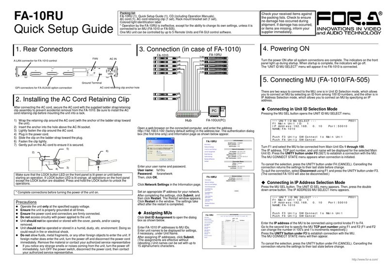
FOR-A FA-10RU User manual

FOR-A

FOR-A FA-10RU User manual

FOR-A LTS-10GR User manual

FOR-A

FOR-A LTS-10GR User manual

FOR-A FC-ONE User manual

FOR-A

FOR-A FC-ONE User manual

FOR-A FA-AUX30 User manual

FOR-A

FOR-A FA-AUX30 User manual

FOR-A FA-10RU User manual

FOR-A

FOR-A FA-10RU User manual

FOR-A FA-10RU User manual

FOR-A

FOR-A FA-10RU User manual

FOR-A FA-95RU User manual

FOR-A

FOR-A FA-95RU User manual

FOR-A FA-10RU User manual

FOR-A

FOR-A FA-10RU User manual

FOR-A FA-95RU User manual

FOR-A

FOR-A FA-95RU User manual

FOR-A MV-42HS User manual

FOR-A

FOR-A MV-42HS User manual

FOR-A FA-10AES-BL User manual

FOR-A

FOR-A FA-10AES-BL User manual

FOR-A FA-10RU User manual

FOR-A

FOR-A FA-10RU User manual

FOR-A FA-95RU User manual

FOR-A

FOR-A FA-95RU User manual

FOR-A FA-10RU User manual

FOR-A

FOR-A FA-10RU User manual

FOR-A FA-10RU User manual

FOR-A

FOR-A FA-10RU User manual

FOR-A FA-10RU User manual

FOR-A

FOR-A FA-10RU User manual

FOR-A FA -10DCCRU User manual

FOR-A

FOR-A FA -10DCCRU User manual

Popular Remote Control manuals by other brands

Amino 513-214-00-00 user guide

Amino

Amino 513-214-00-00 user guide

OKIN OKIN Instruction

OKIN

OKIN OKIN Instruction

Link electronics PSR-826 Specification sheet

Link electronics

Link electronics PSR-826 Specification sheet

York RG93A/BGCEF owner's manual

York

York RG93A/BGCEF owner's manual

Jeckson Electric 47-1010A-T owner's manual

Jeckson Electric

Jeckson Electric 47-1010A-T owner's manual

SkyLink HOUSELINK 318TR user manual

SkyLink

SkyLink HOUSELINK 318TR user manual

HEITECH 10000018 user manual

HEITECH

HEITECH 10000018 user manual

Drayton MiTime T721R Homeowner's guide

Drayton

Drayton MiTime T721R Homeowner's guide

ATI Technologies BroadLink RM Pro manual

ATI Technologies

ATI Technologies BroadLink RM Pro manual

McLED ML-910.501.22.0 quick start guide

McLED

McLED ML-910.501.22.0 quick start guide

NAD HTR10 owner's manual

NAD

NAD HTR10 owner's manual

TECshow WI NODE user manual

TECshow

TECshow WI NODE user manual

Ashly WR-5E user manual

Ashly

Ashly WR-5E user manual

Leviton NE210 instructions

Leviton

Leviton NE210 instructions

VocoPro GIG-MASTER user guide

VocoPro

VocoPro GIG-MASTER user guide

dji SPARK REMOTE CONTROLLER C2 user guide

dji

dji SPARK REMOTE CONTROLLER C2 user guide

RCA RCU600D - Universal Remote Control user manual

RCA

RCA RCU600D - Universal Remote Control user manual

Kuender KD-TPMS-C02 user guide

Kuender

Kuender KD-TPMS-C02 user guide

manuals.online logo
manuals.online logoBrands
  • About & Mission
  • Contact us
  • Privacy Policy
  • Terms and Conditions

Copyright 2025 Manuals.Online. All Rights Reserved.