manuals.online logo
Brands
  1. Home
  2. •
  3. Brands
  4. •
  5. FOR-A
  6. •
  7. Remote Control
  8. •
  9. FOR-A FA-10RU User manual

FOR-A FA-10RU User manual

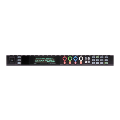
FA-10RU
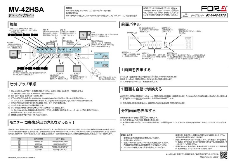
Quick Setup Guide
1. Rear Connectors
2. Installing theAC Cord Retaining Clip
After connecting the AC cord, secure the AC cord with the supplied ladder strap/retaining
clip assembly to prevent accidental removal from the FA-1010. Be sure to install the AC
cord retaining clip before mounting the unit into a rack.
1) Wrap the retaining clip around the AC cord (with the anchor of the ladder strap toward
the unit).
2) Insert the anchor into the hole above the AC IN socket.
3) Lightly fasten the clip around the AC cord.
4) Plug in the power cord.
5) Slide the clip on the ladder strap toward the plug.
6) Fasten the clip tightly.
7) Gently pull on the AC cord to ensure it is secured.
Make sure that the LOCK button LED on the front panel is lit green or unlit before
starting an operation. If LOCK button LED is lit orange, all operations on the front panel
except the LOCK button are disabled. Press and hold the LOCK button to unlock the
operations.
* Complete connections before turning the power of the unit on.
Precautions
Operate the unit only at the specified supply voltage.
Ensure the unit is properly grounded at all times.
Ensure the power cord and connectors are firmly connected.
Do not access circuitry with power applied to the unit.
Unit should not be operated or stored with the cover, panels, and/or casing
removed.
Unit should not be operated or stored in a humid, dusty, etc. environment. Doing so
could result in fire or electrical shock.
Do not allow fluids, metal fragments, or any other foreign objects to enter the unit. If
foreign matter does enter the unit, turn the power off and disconnect the power cord
immediately. Remove the material or contact your authorized service representative
If you notice any strange smells or noises coming from the unit, turn the power off
immediately, turn OFF the power switch, disconnect the power cord, then contact
your authorized service representative.
3. Connection (in case of FA-1010)
Open a web browser on the connected computer, and enter the address
http://192.168.0.100/ (factory default setting) in the address bar. The authentication dialog
box (the first time only) and Information page as shown below appear.
Enter your user name and password.
User name: fa10ru
Password: foranetwork
Then, click OK.
Click Network Settings in the Information page.
Set an appropriate IP address for your network.
After completing the settings, click Submit, and
then click Restart. The Restart window appears.
Click Restart in the window. The settings take
effect after the restart is completed.
◆Assigning MUs
Click Unit ID Assignment to open the dialog
box as shown below.
Enter FA-1010 IP addresses to MU IDs.
Enter unit names to be displayed for settings,
if necessary, under Unit Name.
After assigning IP addresses, click Submit.
(The assignments are effective without
rebooting.) Unit names can be set with up to
15 alphanumeric characters.
4. Powering ON
Turn the power ON after all system connections are complete. The indicators on the front
panel light up during startup. When startup is complete, the indicators will go off.
The “UNIT ID MU SELECT” menu will appear if no FA-1010 is connected.
5. Connecting MU (FA-1010/FA-505)
There are two ways to connect to the MU; one is in Unit ID Selection mode, which allows
you to connect an MU by selecting an ID from among 100 ID numbers, and the other is in
IP Address Selection mode, which allows you to connect an MU by specifying an IP
address.
◆Connecting in Unit ID Selection Mode
Pressing the MU SEL button opens the UNIT ID MU SELECT menu.
--- UNIT ID MU SELECT --- P801
F1 Main Unit ID: 1
IP Address:192.168. 0. 10 Port:50010
NAME:FA-1010
Push F3 Unity SW Connect to Main Unit
Push F4 Unity SW Cancel
Turn F1 and select the MU to be connected from Main Unit IDs 1 through 100.
The IP address, TCP port number, and unit name will be displayed for the selected Main
Unit ID. Press the UNITY button under F3 (SET) to establish a connection with the MU.
The MU CONNECT STATE menu appears when connection is initiated.
To cancel the selection, press the UNITY button under F4 (CANCEL). Cancelling the
connection returns the settings to their last state before change.
To quit the connection, select Disconnect using F1 and press the UNITY button under F3.
(The connected FA-1010 will also be disconnected.)
◆Connecting in IP Address Selection Mode
Press the MU SEL button. The UNIT ID SEL menu appears. Then, press the double
down-arrow button. The IP ADDRESS MU SELECT menu appears.
--- UNIT ID MU SELECT --- P801
F1 Main Unit ID: 1
IP Address:192.168. 0. 10 Port:50010
NAME:FA-1010
Push F3 Unity SW Connect to Main Unit
Push F4 Unity SW Cancel
Enter the IP address of the MU to be connected using control knobs F1 to F4.
Go to the second line to specify the MU TCP port number using F1 and F2 (F1 and F2
can change the number in 100’s and 1’s increments respectively.)
Press the UNITY button under F3 to establish connection with the MU.
The MU CONNECT STATE menu will then appear.
To cancel the selection, press the UNITY button under F4 (CANCEL). Cancelling the
connection returns the settings to their last state before change.
Packing list:
FA-10RU (1), Quick Setup Guide (1), CD (including Operation Manuals),
AC cord (1), AC cord retaining clip (1 set), Rack mount bracket set (1 set),
Colored light identification label
* Operation by the FA-10RU is ineffective, except for the ability to change its own settings, unless it is
connected to an MU (FA-1010 or FA-505).
One MU unit can be controlled by up to 5 Remote Units and FA GUI control software.
2)
4) 3)
5) 6)
FA-1010
FRAMESYNCHRONIZER
INITIALIZATION
OPTIONSLOT
ABCD
INSTALL
VIDEOIN
AUDIOIN
BY-PASS
VIDEO
AUDIO
12345678910
DCPOWER1 GENLOCK
DCPOWER2
FANALARM LTCIN
SDIIN
PC
Hub FA-10GUI(PC)
FA-10RU
FA-1010
FA-1010
FRAMESYNCHRONIZER
INITIALIZATION
OPTIONSLOT
ABCD
INSTALL
VIDEOIN
AUDIOIN
BY-PASS
VIDEO
AUDIO
12345678910
DCPOWER1 GENLOCK
DCPOWER2
FANALARM LTCIN
SDIIN
FA-1010
FRAMESYNCHRONIZER
INITIALIZATION
OPTIONSLOT
ABCD
INSTALL
VIDEOIN
AUDIOIN
BY-PASS
VIDEO
AUDIO
12345678910
DCPOWER1 GENLOCK
DCPOWER2
FANALARM LTCIN
SDIIN
FA-1010
FRAMESYNCHRONIZER
INITIALIZATION
OPTIONSLOT
ABCD
INSTALL
VIDEOIN
AUDIOIN
BY-PASS
VIDEO
AUDIO
12345678910
DCPOWER1 GENLOCK
DCPOWER2
FANALARM LTCIN
SDIIN
FA-1010
FRAMESYNCHRONIZER
INITIALIZATION
OPTIONSLOT
ABCD
INSTALL
VIDEOIN
AUDIOIN
BY-PASS
VIDEO
AUDIO
12345678910
DCPOWER1 GENLOCK
DCPOWER2
FANALARM LTCIN
SDIIN
FA-1010
FRAMESYNCHRONIZER
INITIALIZATION
OPTIONSLOT
ABCD
INSTALL
VIDEOIN
AUDIOIN
BY-PASS
VIDEO
AUDIO
12345678910
DCPOWER1 GENLOCK
DCPOWER2
FANALARM LTCIN
SDIIN
ON
OFF
POWER LOC K
FSLINK
MUSEL
FSSEL
EVENT
GENLOCK FANALARM
FREEZE DCPOWER
TESTSIGNAL
BY-PASS
DISPLAYAREA
FA-10RUREMOTECONTROLU NIT
F1
UNITY
F2
UNITY
F3
UNITY
F4
UNITY
PROC
EMB
INPUT
AES
ANC
ANALOG
CC
SETUP
CLNSW
GAIN
10SYSTEM9
5
12
6
CLIP
DWNMIX
3
OUTPUT
DELAY
7
STATUS0
BY-PASS
MAPPING
4
OPTION8
VIDEO
AUDIO
FA-1010
FRAMESYNCHRONIZER
INITIALIZATION
OPTIONSLOT
ABCD
INSTALL
VIDEOIN
AUDIOIN
BY-PASS
VIDEO
AUDIO
12345678910
DCPOWER1 GENLOCK
DCPOWER2
FANALARM LTCIN
SDIIN
AC cord retaining clip anchor hole
Ground Terminal
GPI connectors for FA-AUX30 option connection
A LAN connector for FA-1010 control
A
C IN
AC100-240V 50/60Hz IN
GPI3GPI2GPI1
TO MU
(10/100/1000BASE-T)
FAN
Check your received items against
the packing lists. Check to ensure
no damage has occurred during
shipment. If damage has occurred,
or items are missing, inform your
supplier immediately.
6. Connecting to an FA-AUX30
Connect GPI connectors on the FA-10RU and FA-AUX30 using cables supplied with the FA-AUX30.
7. Assigning Functions to FA-AUX30 Buttons Using Preset Assignment
Patterns
No functions are pre-assigned to buttons 1 through 30 at shipment.
Preset patterns allow you to assign functions to buttons 1 through 30
simultaneously. Press the MU SELECT button on the FA-10RU front panel,
then press 10 SYSTEM (while the button is lit red) to open the LOAD GPI
PATTERN menu.
--- LOAD GPI PATTERN --- P821
F1 GPI1 BLOCK:None
F2 GPI2 BLOCK:None
F3 GPI3 BLOCK:None
Press F4 UNITY to start pattern loading
Functions can be assigned in 10 button-units under GPI 1 BLOCK, GPI 2
BLOCK, and GPI 3 BLOCK by selecting patterns using corresponding control
knobs F1 to F3. Press the F4 UNITY button to load the selected pattern.
◆Preset Patterns
The following 33 patterns are available.
Select “----“ not to change. Select “None” for no function.
--- Clean SW (Salvo1-10 Load)
None Clean SW (Salvo1-10 Save)
MU Select Clean SW (Salvo1-5 Load/Save)
FS Select Time Code Generator
Process(FS1-FS10) Freeze(FS1-FS10)
Video Level(FS1-FS10) Audio Gain(FS1-FS10)
Chroma Level(FS1-FS10) Audio Delay(FS1-FS10)
Setup/Black(FS1-FS10) Event(No1-10 Load)
Hue(FS1-FS10) Event(No1-10 Save)
CC (FS1-FS10) Event(No1-5 Load/Save)
CC White(FS1-FS10) Menu1 Select
CC Black(FS1-FS10) Menu2 Select
CC Gamma(FS1-FS10) Menu3 Select
BY-PASS(SDI1-SDI10) Menu4 Select
Clean SW (Destination) Status1
Clean SW (Source) Status2
Clean SW (Mode/Take)
◆Corresponding settings
No Setting1 Setting2 Setting3 Setting4
1 None --- --- ---
2 MU Select Menu
Disconnected
ID1-ID100 None
FS1-FS10 ---
3 FS Select FS1-FS10 --- ---
4 Video Process
Video Process Amplifier
Video Level
Chroma Level
Setup/Black level
Hue
Menu
FS1-FS10 ---
5 Color Corrector Color Correction
White Level
Black Level
Gamma Level
Menu
FS1-FS10 ---
6 Freeze (Mode) Menu
Frame
Odd
Even
None
FS1-FS10 None
Menu
7 Freeze (On/Off) On
Off
On/Off
None
All
FS1-FS10 None
Menu
8 By-pass Menu
On
Off
On/Off
All
FS1-FS10 None
Menu
9 Audio Gain(Embedded) Menu
FS1-FS10 --- ---
10 Audio Gain(AES) Menu
Option Slot A-D --- ---
11 Audio Gain(Analog) --- --- ---
12 Audio Delay(Embedded) Menu
FS1-FS10 --- ---
13 Audio Delay(AES) Menu
Option Slot A-D --- ---
14 Audio Delay(Analog) --- --- ---
15 Time Code Menu, Start, Stop, Reset, Preset None, Menu ---
16 Clean Switch Mode Direct Mode
Take Mode
Take ---
Destination Destination1-10
Source Source1(FS1)-10(FS10)
17 Video Test Signal
Menu ---
---
Video Test Signal(Off)
All
FS1-FS10
Video Test Signal(100% CB) On
On/Off
On (with Menu Move)
On/Off (with Menu Move)
Video Test Signal(75% CB)
Video Test Signal(SMPTE CB)
Video Test Signal(RAMP)
18 Audio Test
Signal(Embedded)
Menu ---
---
Audio Test Signal(Off)
FS1-FS10
Audio Test Signal(500Hz) On
On/Off
On (with Menu Move)
On/Off (with Menu Move)
Audio Test Signal(1kHz)
19 Audio Test Signal(AES)
Menu ---
---
Audio Test Signal(Off)
Option Slot A-D
Audio Test Signal(500Hz) On
On/Off
On (with Menu Move)
On/Off (with Menu Move)
Audio Test Signal(1kHz)
20 Audio Test Signal(Analog)
Menu ---
None
Menu
Audio Test Signal(Off) ---
Audio Test Signal(500Hz) On
On/Off
Audio Test Signal(1kHz)
21 All Audio Test
Menu --- ---
Audio Test Signal(Off) None
Menu
Audio Test Signal(500Hz) On
On/Off
Audio Test Signal(1kHz)
22 GPI Lock On, Off, On/Off --- ---
23 Memory Load Event, Salvo Menu, Default, No1-100 FA-10RU, MU
24 Memory Save Event, Salvo Menu, No1-100 FA-10RU, MU
25 Menu Move P000-999 None, FS1-FS10 None, Line1-Line8
26 Color Corrector Split Off, Mode1-3 None, FS1-FS10 None, Menu
The above table is the GPI input pin function setting list. An “---“ indicates no setting.
GPI1 GPI2 GPI3
F
A
-
A
UX30
FA-AUX30 cables (supplied) x 3
AC100-240V50/60Hz IN
GPI3GPI2GPI1
TO MU
(10/100/1000BASE-T)
F
A
-10RU
DCPOWE R
FA-AUX30
AUXILIARYUNIT
GPI 1 BLOCK GPI 2 BLOCK GPI 3 BLOCK
GPI 1-5 GPI 11-15 GPI 21-25
GPI 6-10 GPI 16-20 GPI 26-30
8. Customizing Button Functions
Proceed to the next page (P822) from LOAD GPI PATTERN using the
double down-arrow button to customize functions for each button.
1. Turn F1 and select a port number from GPI 1 through 30.
--- GPI INPUT PORT FUNCTION --- P822
F1 Port:GPI1 PORT 1(FA-AUX30 Right Block)
Setting1:None
Setting2:None
Setting3:None
Setting4:None
2. Press the down-arrow button for F1, F2, F3 and F4 to be displayed to the
left of Setting 1 – 4. Turn the corresponding control knob F1 - F4 and
select functions.
Selecting a function under Setting 1 enables corresponding settings
under Setting 2 – 4. Selectable settings under Setting 1 and their
corresponding settings are shown in the table to the right.
3. Pressing the up-arrow button enables you to select the next port to set
settings. Set functions for each port by repeating steps 1 and 2.
◆Assigning Indication Functions to Buttons
Status indications such as input signal or alarm status can be assigned to
each button LED.
See the FA-10RU Operation Manual, section 9-1-3. “GPI OUTPUT PORT
FUNCTION” for further details.

Other manuals for FA-10RU

8

Other FOR-A Remote Control manuals

FOR-A USF-105AS User manual

FOR-A

FOR-A USF-105AS User manual

FOR-A FA-10AES-BL User manual

FOR-A

FOR-A FA-10AES-BL User manual

FOR-A FA-10RU User manual

FOR-A

FOR-A FA-10RU User manual

FOR-A FA-95RU User manual

FOR-A

FOR-A FA-95RU User manual

FOR-A MV-42HS User manual

FOR-A

FOR-A MV-42HS User manual

FOR-A FA-10RU User manual

FOR-A

FOR-A FA-10RU User manual

FOR-A FA-10RU User manual

FOR-A

FOR-A FA-10RU User manual

FOR-A FA -10DCCRU User manual

FOR-A

FOR-A FA -10DCCRU User manual

FOR-A FA-10RU User manual

FOR-A

FOR-A FA-10RU User manual

FOR-A FA-95RU User manual

FOR-A

FOR-A FA-95RU User manual

FOR-A MV-42HSA User manual

FOR-A

FOR-A MV-42HSA User manual

FOR-A FA-95RU User manual

FOR-A

FOR-A FA-95RU User manual

FOR-A FC-ONE User manual

FOR-A

FOR-A FC-ONE User manual

FOR-A FA-10RU User manual

FOR-A

FOR-A FA-10RU User manual

FOR-A FA-95RU User manual

FOR-A

FOR-A FA-95RU User manual

FOR-A LTS-10GR User manual

FOR-A

FOR-A LTS-10GR User manual

FOR-A FA-AUX30 User manual

FOR-A

FOR-A FA-AUX30 User manual

FOR-A FA-10RU User manual

FOR-A

FOR-A FA-10RU User manual

FOR-A FA-10RU User manual

FOR-A

FOR-A FA-10RU User manual

Popular Remote Control manuals by other brands

Philips SRP 1001 user manual

Philips

Philips SRP 1001 user manual

Walkera DEVO-F12E(WHITE) Setup instructions

Walkera

Walkera DEVO-F12E(WHITE) Setup instructions

Motorola Smart Controller manual

Motorola

Motorola Smart Controller manual

Advent Controls A5 Installation and setup manual

Advent Controls

Advent Controls A5 Installation and setup manual

HP SWING+ quick start guide

HP

HP SWING+ quick start guide

Genius coralis CRH-15-00 operating instructions

Genius

Genius coralis CRH-15-00 operating instructions

FUTABA 3PRKA instruction manual

FUTABA

FUTABA 3PRKA instruction manual

RadioMaster TX16S user manual

RadioMaster

RadioMaster TX16S user manual

Yealink VCR20 user guide

Yealink

Yealink VCR20 user guide

Sony RM-AX4000 - Integrated Remote Commander Software manual

Sony

Sony RM-AX4000 - Integrated Remote Commander Software manual

Radio Shack Kameleon owner's manual

Radio Shack

Radio Shack Kameleon owner's manual

Universal Remote Contorl UR2 211 operating manual

Universal Remote Contorl

Universal Remote Contorl UR2 211 operating manual

Sony PlayStation Portal instruction manual

Sony

Sony PlayStation Portal instruction manual

QNect QN-WIR01 quick start guide

QNect

QNect QN-WIR01 quick start guide

Inmotion controls 140 Series user manual

Inmotion controls

Inmotion controls 140 Series user manual

CUAV TeleLink manual

CUAV

CUAV TeleLink manual

Pluggit APRC Operating and installation instructions

Pluggit

Pluggit APRC Operating and installation instructions

Telefunken TRC 200 manual

Telefunken

Telefunken TRC 200 manual

manuals.online logo
manuals.online logoBrands
  • About & Mission
  • Contact us
  • Privacy Policy
  • Terms and Conditions

Copyright 2025 Manuals.Online. All Rights Reserved.