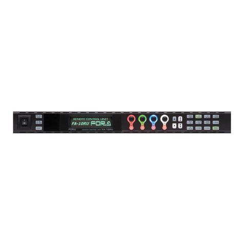
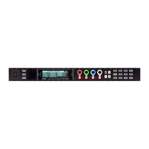
FOR-A FA-10RU User manual

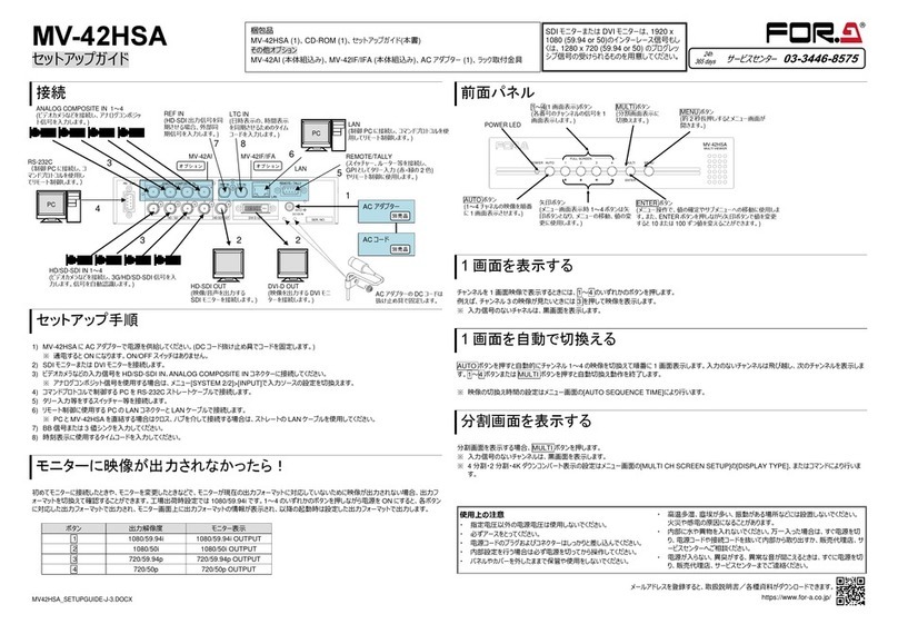
FA-10RU for FA-9600
Remote Control Unit
4th Edition - Rev. 6
Software Version 8.81 Higher
OPERATION
MANUAL

2
Edition Revision History
Edit.
Rev.
Date
Description
Section/Page
1
-
2017/09/15
2
-
2017/09/22
Significant changes in functions
2
1
2017/11/28
Revised USF-106UDC/DC-12G Event Memory
function.
Sec. 9
2
2
2018/04/16
Default value changed from Disable to Enable for
Directional Interpolation
Default value changed from Pass to Overwrite for
VIDEO PAYLOAD ID on FS1 and FS2
FA-96EX12G06 option added.
5-18
5-22
5-13, 5-35
3
-
2018/09/10
Supports FA-9600 Version 2 and later.
4
-
2019/04/12
Supports FA-9600 Version 3 and later.
4
1
2019/05/09
Supports FA-9600 Version 3.20 and later
4
2
2019/06/17
Added commands to external command control.
11
4
3
2019/08/21
Supports FA-9600 Version 3.30 and later.
4
4
2019/09/05
Supports FA-9600 Version 3.40 and later.
5-24, 6-24, etc.
4
5
2019/11/25
Supports FA-9600 Version 3.50 and later.
5-36, 5-38, etc.
4
6
2020/02/18
Supports FA-9600 Version 3.60 and later.
6, etc.
Software Version and Supported Options
FA-10RU version
Newly supported Feature/Option
Note
FPGA1: 1.00
FPGA2: 1.00
Soft: 6.00
FA-96PS
FA-96EX3G44-R (Slot A)
FA-96AES-UBL (SlotB)
FA-96GPI (SlotB/C)
FA-964K
FA-96UDC
FA-96AHDR
FPGA1: 1.00
FPGA2: 1.00
Soft: 6.10
FA-96AES-UBLC (Slot B/C)
FA-96DB9-CBL (Slot E)
Changes according to FA-9600 update
FPGA1: 1.00
FPGA2: 1.00
Soft: 7.00
USF-10UDC-AHDR
USF-10DC-AHDR
USF-106UDC/DC-12G event memory data cannot be
saved by FA-10RU.
FPGA1: 1.00
FPGA2: 1.00
Soft: 7.10
Revised USF-10UDC/DC-12G
Event Memory function.
USF-106UDC/DC-12G event memory data can be
saved by FA-10RU.
Factual errors corrected.
FPGA1: 1.00
FPGA2: 1.00
Soft: 7.30
FA-96EX12G06 (Slot A)
Default values changed in the FA-9600 menu.
FA-96EX12G06 option added
FPGA1: 1.00
FPGA2: 1.00
Soft: 7.40
FA-96DIN4-CBL(Slot D)
FA-9600 Version 2 support
FPGA1: 1.00
FPGA2: 1.00
Soft: 8.30
FA-96AHDR2
FA-9600 Version 3 support
External command control (MU SELECT command)
FPGA1: 1.00
FPGA2: 1.00
Soft: 8.40
FA-9600 Version 3.20 support
Sony SR-Live support
FPGA1: 1.00
FPGA2: 1.00
Soft: 8.44
FS selection support (MU Select command)
Status request command support

3
FPGA1: 1.00
FPGA2: 1.00
Soft: 8.50
FA-96SFPC4 (Slot A)
FA-96ANA-AUD (Slot B)
FA-9600 Version 3.30 support
FA-96SFPC4 and FA-96ANA-AUD options added.
FPGA1: 1.00
FPGA2: 1.00
Soft: 8.60
FA-9600 Version 3.40 support.
FPGA1: 1.00
FPGA2: 1.00
Soft: 8.70
FA-9600 Version 3.50 support.
FPGA1: 1.00
FPGA2: 1.00
Soft: 8.81
FA-96MADI
FA-9600 Version 3.60 support.
FA-10RU versions can be seen in the “FA-10RU INFORMATION”menu (see Sec. 8-6).

4
Precautions
Important Safety Warnings
[Power]
Caution
Operate unit only at the specified supply voltage.
Disconnect the power cord via the power plug only. Do not pull on the cable portion.
Stop
Do not place or drop heavy or sharp-edged objects on the power cord. A damaged
cord can cause fire or electrical shock hazards. Regularly check the power cord for
excessive wear or damage to avoid possible fire / electrical hazards.
Caution
Ensure the power cord is firmly plugged into the AC outlet.
[Grounding]
Caution
Ensure the unit is properly grounded at all times to prevent electrical shock.
Hazard
Do not ground the unit to gas lines, units, or fixtures of an explosive or dangerous
nature.
[Operation]
Hazard
Do not operate the unit under hazardous or potentially explosive atmospheric
conditions. Doing so could result in fire, explosion, or other hazardous results.
Hazard
Do not allow liquids, metal pieces, or other foreign materials to enter the unit. Doing so
could result in fire, other hazards, or a unit malfunction.
If a foreign material does enter the unit, turn the power off and immediately disconnect
the power cord. Remove the material and contact an authorized service representative
if damage has occurred.
[Transportation]
Hazard
Handle with care to avoid impact shock during transit, which may cause malfunction.
When you need to transport the unit, use the original or suitable alternative packing
material.

5
[Circuitry Access]
Do not remove covers, panels, casing, or access the circuitry with power applied to the
unit. Turn the power off and disconnect the power cord prior to removal. Internal
servicing / adjustment of unit should only be performed by qualified personnel.
Stop
Do not touch any parts / circuitry with a high heat factor.
Capacitors can retain enough electric charge to cause mild to serious shock, even after
the power has been disconnected. Capacitors associated with the power supply are
especially hazardous.
Hazard
Unit should not be operated or stored with cover, panels, and / or casing removed.
Operating the unit with circuitry exposed could result in electric shock / fire hazards or
a unit malfunction.
[Potential Hazards]
Caution
If abnormal odors or noises are noticed coming from the unit, immediately turn the
power off and disconnect the power cord to avoid potentially hazardous conditions. If
problems similar to the above occur, contact an authorized service representative
before attempting to operate the unit again.
[Rack Mount Brackets, Ground Terminal, and Rubber Feet]
Caution
To rack-mount or ground the unit, or to install rubber feet, do not use screws or
materials other than those supplied. Doing so may cause damage to the internal
circuits or components of the unit. If you remove the rubber feet that are attached to the
unit, do not reinsert the screws that secure the rubber feet.
[Consumables]
Caution
Consumable items that are used in the unit must be periodically replaced. For further
details on which parts are consumables and when they should be replaced, refer to the
specifications at the end of the Operation Manual. Since the service life of the
consumables varies greatly depending on the environment in which they are used,
such items should be replaced at an early date. For details on replacing consumable
items, contact your dealer.

6
Upon Receipt
FA-10RU units and their accessories are fully inspected and adjusted prior to shipment. Check your
received items against the packing lists below. Check to ensure no damage has occurred during
shipment. If damage has occurred, or items are missing, inform your supplier immediately.
FA-10RU Box
ITEM
QTY
REMARKS
FA-10RU
1
AC Cord
1 set
(Including AC cord retaining clip)
Rack Mount Brackets
1 set
EIA standard type
CD-ROM
1
FA GPIO Editor installation disc
User manual (PDF) included
Quick Setup Guide
1
Colored Light Indication Label
1
Trademarks
Microsoft, Windows, Internet Explorer, and Windows Media are either registered trademarks or
trademarks of Microsoft Corporation in the United States and/or other countries.
Firefox is a registered trademark of the Mozilla Foundation.
Dolby is a trademark of Dolby Laboratories.
* All other trademarks are trademarks or registered trademarks of their respective owners.
Installing the AC Cord Retention Clip
Secure the AC cord with the supplied ladder strap/retention clip assembly to prevent accidental
removal from the unit.
Installing the clip
1) Wrap the retention clip around the AC cord (with the anchor of the ladder strap toward the
unit.)
2) Insert the anchor into the hole next to the AC IN socket.
3) Lightly fasten the clip around the AC cord.
4) Plug in the power cord.
5) Slide the clip on the ladder strap toward the plug.
6) Fasten the clip tightly.
7) Gently pull on the AC cord to ensure it is secured.
2)
4)
3)
5)
6)

7
Unplugging the AC cord
1) Push the tab on the retention clip up to
unfasten the clip.
2) Push the tab on the ladder strap up and
slide the clip back.
3) Unplug the AC cord.
Colored Light Identification Label
The colored light identification label can be attached to the front panel to assist in identifying colored
light indication.
1)
2)
POWER
ON
OFF
MU SEL
LOCK
FS SEL
FS LINK
EVENT
GENLOCK
FREEZE
TEST SIGNAL
BY-PASS
FAN ALARM
DC POWER
REMOTE CONTROL UNIT FA-10RU
DISPLAY AREA F1 F2 F3 F4
UNITY UNITY UNITY UNITY
12 3 4
56 7
910 0
OPTION8
PROC
EMB
CC
SETUP
CLIP
DWN MIX
BY-PASS
MAPPING
INPUT
AES
CLN SW
GAINI
OUTPUT
DELAY
ANC
ANALOG SYSTEM STATUS VIDEO
AUDIO
MU /FS
VIDEO
AUDIO

8
Table of Contents
1. Prior to Starting...................................................................................................................................12
1-1. Overview ...................................................................................................................................12
1-2. Features....................................................................................................................................12
1-3. About This Manual....................................................................................................................12
2. Panel Descriptions..............................................................................................................................13
2-1. Front Panel................................................................................................................................13
2-2. Rear Panel ................................................................................................................................14
2-3. Internal Settings ........................................................................................................................15
2-3-1. Dipswitch Settings .............................................................................................................15
3. Connection .........................................................................................................................................16
3-1. Basic Configuration...................................................................................................................16
3-2. Connection with Option/Expansion Units..................................................................................17
3-3. System Requirements (Web-based Control)............................................................................17
4. Front Panel Operations ......................................................................................................................18
4-1. Powering ON.............................................................................................................................18
4-2. Connecting FA-9600 Units........................................................................................................18
4-2-1. Connecting in Unit ID Selection Mode...............................................................................18
4-2-2. Connecting in IP Address Selection Mode ........................................................................19
4-2-3. CONNECT STATE Menu ..................................................................................................19
4-3. Basic Operations.......................................................................................................................20
4-3-1. Accessing Menus...............................................................................................................20
4-3-2. Arrow Buttons ....................................................................................................................21
4-3-3. Consecutive Viewing of Settings .......................................................................................21
4-3-4. Three FA-9600 Operation Modes......................................................................................21
4-3-5. Menu List ...........................................................................................................................22
4-3-6. Changing Setting Values ...................................................................................................24
4-3-7. Resetting to Default ...........................................................................................................25
4-3-8. Switching between FS1 and FS2.......................................................................................25
5. VIDEO Menus.....................................................................................................................................26
5-1. VIDEO PROCESS AMPLIFIER ................................................................................................26
5-2. GAMMA/COLOR.......................................................................................................................27
5-3. IN/OUT GAMMA/COLOR..........................................................................................................28
5-4. OOTF FOR HLG (INPUT SIDE)(OUTPUT SIDE).....................................................................28
5-5. OPTIONAL FUNCTION (FA-96AHDR2)...................................................................................29
5-5-1. About OOTF Related Parameters .....................................................................................30
5-6. AREA MARKER (FA-96AHDR/96AHDR2)...............................................................................30
5-7. DYNAMIC RANGE GAIN CONTROL .......................................................................................31
5-8. COLOR CORRECTION (BALANCE)........................................................................................31
5-9. COLOR CORRECTION (DIFF).................................................................................................32
5-10. KNEE (RGB CLIP) White/Black..............................................................................................32
5-11. YCbCr CLIP ............................................................................................................................33
5-12. SDI BY-PASS..........................................................................................................................34
5-13. INPUT SELECT (Sync)...........................................................................................................34
5-14. INPUT SELECT(Proc) / LINKAGE..........................................................................................36
5-15. OUTPUT SELECT ..................................................................................................................37
5-16. OUTPUT SELECT (Slot A) .....................................................................................................37
5-17. FORMAT CONVERTER (FA-96UDC)....................................................................................40
5-18. ADJUST TIMING (FA-96UDC) ...............................................................................................41
5-19. RESIZE (FA-96UDC)..............................................................................................................42
5-20. IMPROVEMENT IN CONVERTER (FA-96UDC)....................................................................43
5-21. FILTER SETTINGS (FA-96UDC)............................................................................................43
5-22. ANTIALIAS H/V (FA-96UDC)..................................................................................................44

9
5-23. ENHANCE H/V (FA-96UDC) ..................................................................................................44
5-24. NOISE REDUCER (FA-96UDC).............................................................................................45
5-25. UHD UPCONVERSION (FS1) (FA-96UDC/964K) .................................................................45
5-26. GPI UTILITY (FA-96GPI/96DB9-CBL)....................................................................................46
5-27. SLOT B / SLOT C GPI FUNCTION (FA-96GPI).....................................................................46
5-28. SLOT E GPI FUNCTION (FA-96DB9-CBL)............................................................................48
5-29. ANCILLARY MULTIPLEX.......................................................................................................49
5-30. VIDEO PAYLOAD ID ..............................................................................................................49
5-31. TIME CODE MULTIPLEX.......................................................................................................50
5-32. TCG1-1 (LTC), TCG2-1 (LTC)................................................................................................50
5-33. TCG1-2 (VITC/DVITC), TCG2-2 (VITC/DVITC)......................................................................51
5-34. TCG CONTROL (Color Processor1/2)....................................................................................51
5-35. LTC OUTPUT SELECT (OP) (FA-96DIN4-CBL)....................................................................52
5-36. ANC DATA INSERTION .........................................................................................................52
5-37. VIDEO PAYLOAD ID LINKAGE..............................................................................................53
5-38. ANC USER PACKET (Planned for future support).................................................................53
5-39. ANC USER PACKET INSERTION (Planned for future support) ............................................54
5-40. SYNCHRONIZER FORMAT...................................................................................................55
5-41. SYNCHRONIZER ...................................................................................................................55
5-42. VIDEO FREEZE......................................................................................................................56
5-43. VIDEO TEST SIGNAL.............................................................................................................56
5-44. FRAME DELAY.......................................................................................................................57
5-45. VIDEO INPUT STATUS..........................................................................................................58
5-46. VIDEO INPUT STATUS (Slot A).............................................................................................58
5-47. PROCESS SIGNAL STATUS.................................................................................................59
5-48. VIDEO OUTPUT STATUS......................................................................................................59
5-49. INPUT PAYLOAD ID...............................................................................................................60
5-50. INPUT PAYLOAD ID (SLOT A) ..............................................................................................61
5-51. INPUT TIME CODE DETECTION ..........................................................................................61
5-52. INPUT ANCILLARY DETECTION 1-3....................................................................................62
5-53. OUTPUT PALYLOAD ID.........................................................................................................62
5-54. OUTPUT PAYLOAD ID (SLOT A) ..........................................................................................63
5-55. INPUT ARIB B39 VIDEO MODE ............................................................................................63
5-56. SFPC4 MODULE STATUS.....................................................................................................63
5-57. MAIN UNIT STATUS / INFORMATION / VERSION...............................................................64
5-58. OPTION SLOT A-D/E INFORMATION...................................................................................65
5-59. MU OPERATION INFORMATION..........................................................................................65
6. AUDIO Menus ....................................................................................................................................66
6-1. EMBEDDED AUDIO DEMULTIPLEXER ..................................................................................66
6-2. EMBEDDED AUDIO MULTIPLEXER .......................................................................................66
6-3. AUDIO MUX. MODE (ARIB STD-B39) .....................................................................................67
6-4. EMBEDDED AUDIO IN POLARITY..........................................................................................68
6-5. SOURCE AUDIO SELECT .......................................................................................................68
6-6. SAMPLING RATE CONVERTER (SRC) ..................................................................................69
6-7. MONO SUM SETTINGS (1-16) ................................................................................................69
6-8. AUDIO DOWN MIX1-2..............................................................................................................70
6-9. EMB. AUDIO OUTPUT MAPPING ...........................................................................................71
6-10. AES AUDIO MAPPING...........................................................................................................71
6-11. ANALOG AUDIO MAPPING (FA-96ANA-AUD) .....................................................................72
6-12. HDMI AUDIO OUTPUT SELECT............................................................................................72
6-13. MADI OUTPUT MAPPING (FA-96MADI) ...............................................................................73
6-14. HDMI AUDIO OUTPUT SELECT (FA-96MADI) .....................................................................73
6-15. AES AUDIO INPUT HYSTERESIS.........................................................................................74
6-16. AES TERMINAL IN/OUT SET ................................................................................................74
6-17. AES AUDIO INPUT POLARITY..............................................................................................75
10
6-18. EMBEDDED AUDIO OUTPUT GAIN......................................................................................75
6-19. AES AUDIO OUTPUT GAIN...................................................................................................75
6-20. ANALOGAUDIOINPUT/OUTPUTGAIN(FA96ANA-AUD)............................................................76
6-21. MADI OUTPUT GAIN (FA-96MAD)........................................................................................76
6-22. AUDIO INPUT DELAY............................................................................................................77
6-23. Dolby E ALIGNMENT..............................................................................................................77
6-24. ADDITIONAL AUDIO DELAY (FA-96UDC)............................................................................78
6-25.ANALOGAUDIOINPUT/OUTPUTLEVEL(FA-96ANA-AUD)..............................................................78
6-26. ANALOG AUDIO INPUT POLARITY (FA-96ANA-AUD) ........................................................79
6-27. ANALOG AUDIO SETTINGS (FA-96ANA-AUD)....................................................................79
6-28. AUDIO SYSTEM.....................................................................................................................80
6-29. AUDIO MUTE/TEST SIGNAL.................................................................................................81
6-30. EMBEDDED1-2 AUDIO INPUT STATUS...............................................................................82
6-31. AES AUDIO INPUT STATUS .................................................................................................82
6-32. ANALOG AUDIO INPUT STATUS..........................................................................................82
6-33. MADI AUDIO INPUT STATUS (FA-96MADI) .........................................................................83
6-34. EMB. AUDIO PHASE ERROR................................................................................................83
6-35. INPUT ARIB B39 AUDIO MODE ............................................................................................83
6-36. EMB1-2 AUDIO OUTPUT STATUS........................................................................................84
6-37. HDMI AUDIO OUTPUT STATUS ...........................................................................................84
6-38. AES AUDIO OUTPUT STATUS .............................................................................................84
6-39. ANALOG AUDIO OUTPUT STATUS (FA-96ANA-AUD)........................................................85
6-40. MADI AUDIO OUTPUT STATUS (FA-96MADI) .....................................................................85
7. Event Memory ....................................................................................................................................86
7-1. LOAD EVENT MEMORY..........................................................................................................86
7-2. SAVE EVENT MEMORY ..........................................................................................................86
8. FA-10RU SYSTEM Menu...................................................................................................................87
8-1. LOAD GPI INPUT PATTERN ...................................................................................................87
8-2. GPI INPUT PORT FUNCTION..................................................................................................88
8-2-1. Setting 1-4 List...................................................................................................................88
8-2-2. Settings 1-4 Details............................................................................................................90
8-2-3. GPI OUTPUT PORT FUNCTION......................................................................................97
8-2-4. GPI OUTPUT Functions ....................................................................................................98
8-3. GPI OUTPUT BRIGHTNESS....................................................................................................98
8-4. FRONT PANEL SET.................................................................................................................99
8-5. STATUS LED MODE SETTINGS.............................................................................................99
8-6. FA-10RU INFORMATION.......................................................................................................100
8-7. FA-10RU NETWORK INFORMATION ...................................................................................100
9. Web Browser Settings......................................................................................................................101
9-1. Information ..............................................................................................................................102
9-2. Network Settings.....................................................................................................................103
9-3. User Account Settings.............................................................................................................103
9-4. Unit ID Assignment .................................................................................................................104
9-5. Event Naming..........................................................................................................................104
9-6. Backup & Restore ...................................................................................................................105
9-6-1. Configuration Data Backup..............................................................................................105
9-6-2. Event Data Backup..........................................................................................................106
9-7. Restart.....................................................................................................................................106
10. GPI Interface ..................................................................................................................................107
10-1. FA GPIO Editor.....................................................................................................................107
10-1-1. Software Installation ......................................................................................................107
10-1-2. Verifying GPIO Editor Version.......................................................................................109
10-1-3. Connecting FA GPIO Editor to the FA-10RU ................................................................110
10-1-4. Setting GPI Functions....................................................................................................111

11
10-1-5. Exporting / Importing GPI Settings ................................................................................112
10-2. GPI Input Patterns.................................................................................................................113
10-3. GPI 1-GP I3 Pin Assignments...............................................................................................117
11. Command Control ..........................................................................................................................119
11-1. Communication Method........................................................................................................119
11-2. Command..............................................................................................................................119
11-2-1. Power On.......................................................................................................................119
11-2-2. MU Select Command.....................................................................................................119
11-2-3. Connection Status Request Command (Status)............................................................120
12. Initializing FA-10RU........................................................................................................................121
13. Specifications and Dimensions ......................................................................................................122
13-1. Specifications........................................................................................................................122
13-2. External Dimensions.............................................................................................................122

12
1. Prior to Starting
1-1. Overview
The FA-10RU is a remote control unit that allows you to remotely control the following frame
synchronizers and USF module cards via network:
FA-505
FA-1010
FA-9600
USF-106UDC-12G and USF-106DC-12G
USF-1043FS
This manual explains how to operate FA-9600 from FA-10RU.
For controlling other devices from FA-10RU, refer to their respective FA-10RU Operation Manuals.
1-2. Features
Control over FA-9600 via Ethernet
Up to 100 FA-9600 units can be connected to be selected for control
IP address FA-9600 selection and control
Simultaneous control over one FA-9600 from five FA-10RU units (including FA-9600GUI)
Storage and recall of up to 100 events
GPI control with 30 input and output functions
MU switching by remote LAN commands
FA-AUX30 option for additional control buttons
1-3. About This Manual
This manual is intended to help the user easily operate this product and make full use of its
functions during operation. Before connecting or operating your unit, read this operation manual
thoroughly to ensure you understand the product. Afterwards, store this manual in a safe place for
future reference.

13
2. Panel Descriptions
2-1. Front Panel
No.
Name
Description
Ref.
1
POWER
switch
Used to turn the unit ON / OFF. Pressing the "|" side turns on
the power.
2
MU SELECT
LOCK
button
Pressing the button opens a menu to select an FA-9600 to
control.
Holding down the button locks front panel buttons. Lit orange
when LOCK is on.
To release LOCK, hold down the button again.
4-2
3
FS SEL
FS LINK
button
Used to switch menu button (9) functions after the FA-10RU is
connected to an FA-9600.
Unlit: Selects menu items.
Lit red: Selects FS1 or FS2 using menu buttons.
4-3-8
4
EVENT
button
Used to save and load events.
7
5
Status
indicator
GENLOCK
Lit green
An external reference signal input is
present in the FA-9600.
5-45
Unlit
Flashing
green (*1)
No external reference signal input is
present in the FA-9600.
FREEZE
Lit green
Flashing
green (*1)
FREEZE is turned On for at least one
FS in the FA-9600.
5-42
Unlit
All FREEZE settings are turned Off in
the FA-9600.
TEST
SIGNAL
Lit green
Flashing
green (*1)
VIDEO or AUDIO TEST SIGNAL is
turned On for at least one FS in the
FA-9600.
5-43
6-29
Unlit
All VIDEO and AUDIO TEST SIGNAL
settings are turned Off in the FA-9600.
BY-PASS
Lit green
Flashing
green (*1)
SDI VIDEO BY-PASS or COLOR
CORRECTION BY-PASS is turned
On (process bypassed) for at least
one FS in the FA-9600.
5-12
Unlit
All SDI VIDEO BY-PASS and COLOR
CORRECTION BY-PASS settings are
turned Off in the FA-9600.
FAN
ALARM
Lit red
Flashing
red (*1)
Fan(s) on FA-10RU and/or FA-9600
have failed. Turn the power of the unit
OFF, and replace the failed fan(s) if
needed.
5-57
8-6
Unlit
All fans are operating normally.
POWER
ON
OFF
MU SEL
LOCK
FS SEL
FS LINK
EVENT
GENLOCK
FREEZE
TEST SIGNAL
BY-PASS
FAN ALARM
DC POWER
REMOTE CONTROL UNIT FA-10RU
DISPLAY AREA F1 F2 F3 F4
UNITY UNITY UNITY UNITY
12 3 4
56 7
910 0
OPTION8
PROC
EMB
CC
SETUP
CLIP
DWN MIX
BY-PASS
MAPPING
INPUT
AES
CLN SW
GAINI
OUTPUT
DELAY
ANC
ANALOG SYSTEM STATUS VIDEO
AUDIO

14
No.
Name
Description
Ref.
5
Status
indicator
DC
POWER
(*2)
Lit red
Flashing red
(*1)
A power failure has occurred.
Power Off the unit and consult your
FOR-A reseller.
5-57
Unlit
Power supply is normal.
6
Menu display
Used to display menus and make operational settings.
4-3
7
Controls (F1-F4)
UNITY buttons
Used to change operational settings. Turn and select
values.
The Unity buttons return the settings to the default
values.
4-3
8
Arrow buttons
Single-arrow
button
Used to move between parameters.
(Indicators light up to indicate the
accessible direction.)
4-3
Double-arrow
button
Used to move between menus.
(Indicators light up to indicate the
accessible direction.))
4-3
9
Menu buttons
Used to select menus.
4-3-1
4-3-2
(*1) The combination of Unlit/Flashing or Lit/Flashing is selectable. Refer to section “8-5. STATUS LED
MODE SETTINGS” for details. The default setting is Lit.
(*2) Functioning only when if FA-96PS is installed on FA-9600.
2-2. Rear Panel
No.
Name
Description
Ref.
1
TO MU
A LAN connector for FA-9600 control.
Set the unique IP address and connect to the network.
3
2
GPI 1-GPI 3
Used to connect an FA-AUX30 or external expansion switch
panel(s).
3-2
8-1
8-2
8-3
10
3
FAN
Used to air-cool the unit to prevent overheating. Do not block
the ventilation with other equipment or objects. The FAN
ALARM on the front panel lights up if the fan fails.
8-6
4
Ground
Terminal
Used to ground the unit to protect operators against static
electricity and electrical shock.
5
AC cord
retaining clip
anchor hole
Used to anchor the AC cord retaining clip.
6
AC IN
Used to connect the unit to an AC power source.
(AC100V-240V 50/60Hz)
AC100-240V 50/60Hz IN
GPI3GPI2GPI1
TO MU
(10/100/1000BASE-T)

15
2-3. Internal Settings
IMPORTANT
Note that internal switch settings should not be changed from factory defaults. If you have
accidentally changed the settings, return them to the factory default settings as shown in this
section.
Be sure to have qualified technical personnel perform the settings and adjustments in the
interior, or contact your dealer.
CAUTION
Do not access any internal cards while the unit is powered ON. Always power
OFF all connected units / disconnect power cords prior to accessing the
interior. To protect boards from electrostatic damage, do not touch the
components on the boards.
2-3-1. Dipswitch Settings
Refer to section 10-3. “GPI 1 - GPI 3 Pin Assignments”for details on GPI OUT 1-8
Dipswitch S3 Settings
Pin no.
Default setting
Description
1-8
OFF
Do not change.
Dipswitch S101 Settings
Pin no.
Default setting
Description
1-8
OFF
OFF: Sets GPI OUT1-8 to open collector output.
ON: Sets GPI OUT1-8 to +5V TTL level output.
Dipswitch S102 Settings
Pin no.
Default setting
Description
1-8
OFF
OFF: Sets GPI OUT9-16 to open collector output.
ON: Sets GPI OUT9-16 to +5V TTL level output.
Dipswitch S103 Settings
Pin no.
Default setting
Description
1-8
OFF
OFF: Sets GPI OUT17-22 to open collector output.
ON: Sets GPI OUT17-22 to +5V TTL level output.
Dipswitch S104 Settings
Pin no.
Default setting
Description
1-6
OFF
OFF: Sets GPI OUT26-30 to open collector output.
ON: Sets GPI OUT26-30 to +5V TTL level output.
7
OFF
Do not change.
8
OFF
Do not change.

16
3. Connection
3-1. Basic Configuration
Specify unique IP addresses for all devices connected to the network.
See Sec. 9-2. Network Settings for details on setting IP addresses.
One FA-9600 unit can be controlled by up to 5 units of FA-10RU and/or FA-10DCCRU maximum.
An attempted 6th connection will not be accepted.
AC100-240V50/60Hz IN
GPI3GPI2GPI1
TOMU
(10/100/1000BASE-T)
AC100-240V50/60Hz IN
GPI3GPI2GPI1
TOMU
(10/100/1000BASE-T)
AC100-240V50/60Hz IN
GPI3GPI2GPI1
TOMU
(10/100/1000BASE-T)
AC100-240V50/60Hz IN
GPI3GPI2GPI1
TOMU
(10/100/1000BASE-T)
AC100-240V50/60Hz IN
GPI3GPI2GPI1
TOMU
(10/100/1000BASE-T)
Ethernet hub
FA-9600GUI(PC)
FA-10RU
FA-9600
PC

17
3-2. Connection with Option/Expansion Units
Connection with the FA-AUX30 option
Connection with a user-made switch box
See Sec. 10. “GPI Interface”for details on GPI connectors.
3-3. System Requirements (Web-based Control)
To utilize the FA-10RU from a web browser, your computer must meet the following requirements.
OS
Windows® 7 /8.1
Professional (32/64bit)
Windows® 10
Professional (32/64bit)
CPU
Intel® Core™2 Duo processor
2GHz or higher
Intel® Core™2 Duo processor
2GHz or higher
Web browser
Internet Explorer® 11
Firefox®54
Chrome®59
Opera®46
Internet Explorer® 11
Firefox®24
Chrome®59
Opera®46
Free memory
2GB or more
4GB or more
Display
Resolution of 1024×768 pixels or higher.
Must be capable of full color (24-bit) display
Network port
Ethernet, at least one port
100BASE-TX/1000BASE-T
Network cable
100BASE-TX: Category 5 or better
1000BASE-T: Category 6, or enhanced category 5
GPI1 GPI2 GPI3
FA-AUX30
FA-AUX30 supplied cables x 3
AC100-240V 50/60Hz IN
GPI3GPI2GPI1
TO MU
(10/100/1000BASE-T)
FA-10RU
Connect to GPI1-GPI3 connector
AC100-240V 50/60Hz IN
GPI3GPI2GPI1
TO MU
(10/100/1000BASE-T)
FA-10RU
FS1
FS2
FS3
FS4
FS5
FS6
FS7
FS8
FS9
FS10

18
4. Front Panel Operations
4-1. Powering ON
Turn the power ON after all system connections are complete. The indicators on the front panel
light up during startup. When startup is complete, the indicators will go off.
The UNIT ID MU SELECT menu will appear if no FA-9600 is connected.
- - - U N I T I D M U S E L E C T - - - P 8 0 1
F 1 M a i n U n i t I D : 3
I P A d d r es s : 1 9 2 . 1 6 8 . 0. 1 0 Po r t : 5 0 100
N A M E : FA - 9 6 0 0 D e f a u l t
P u s h F 3 U n i t y S W C o n n e c t t o M a i n U n i t
P u s h F 4 U n i t y S W C a n c e l
4-2. Connecting FA-9600 Units
The FA-10RU is inoperative until an FA-9600 is connected.
There are two ways to connect to the FA-9600; one is in Unit ID Selection mode, which allows you
to connect an FA-9600 by selecting an ID from among 100 ID numbers, and the other is in IP
Address Selection mode, which allows you to connect an FA-9600 by specifying an IP address.
4-2-1. Connecting in Unit ID Selection Mode
To connect to an FA-9600 in Unit ID Selection Mode, the unit must be registered in the
FA-10RU. See Sec. 9-4. “Unit ID Assignment”for details on how to register FA-9600 units.
Connecting to FA-9600
1) Pressing the MU SEL button opens the UNIT ID MU SELECT menu.
- - - U N I T I D M U S E L E C T - - - P 8 0 1
F 1 M a i n U n i t I D : 3
I P A d d r es s : 1 9 2. 1 6 8 . 0 . 1 0 P o r t : 50 1 0 0
N A M E : FA - 9 6 0 0 D e f a u l t
P u s h F 3 U n i t y S W C o n n e c t t o M a i n U n i t
P u s h F 4 U n i t y S W C a n c e l
2) Turn F1 and select a Unit ID number from Main Unit IDs 1 through 100 to specify the
FA-9600 to be connected. The IP address, TCP port number and unit name will be
displayed for the selected Main Unit ID.
3) Press the F3 UNITY button to establish a connection with the selected FA-9600.
The MU CONNECT STATE menu appears when connection is initiated.
To cancel the process, press the F4 UNITY (Cancel) button. Cancelling the connection
returns the settings to their last state before change.
4) The connection is successful, “Connected” will appear under State in the menu.
Disconnecting from FA-9600
Select Disconnect by F1 and press the F3 UNITY button.

19
4-2-2. Connecting in IP Address Selection Mode
1) Press the MU SEL button. The UNIT ID SEL menu appears.
2) Press the double down-arrow button. The IP ADDRESS MU SELECT menu appears.
- - - I P A D D R E S S M U S E L E C T - - - P 8 0 2
F1- F 4 I P A d d r e s s :1 9 2 . 1 6 8. 0 . 1 0
T C P P o r t : 5 0 0 1 6
N A M E : F A - 9 6 0 0 D e f a ul t
F 1 t o F 4 I P A d d r es s s e t
P u s h F 3 U n i t y S W C o n n e c t t o M a i n U n i t
P u s h F 4 U n i t y S W C a n c e l
3) Enter the IP address of the FA-9600 to be connected using control knobs F1 to F4.
4) Go to the second line to specify the FA-9600 TCP port number using F1 and F2 (F1 and
F2 can change the number in 100’s and 1’s increments respectively.)
5) Press the F3 UNITY button to establish a connection with the selected FA-9600.
The MU CONNECT STATE menu appears when connection is initiated.
To cancel the process, press the F4 UNITY (Cancel) button. Cancelling the connection
returns the settings to their last state before change.
6) The connection is successful, “Connected” will appear under State in the menu.
4-2-3. CONNECT STATE Menu
Connections with FA-9600 units can be viewed in the CONNECT STATE menu.
- - - M U C O N N E C T S T A T E - - - P 8 0 3
I P A d d r e s s :1 9 2 . 1 68 . 0 . 1 0 P o r t : 5 0 1 0 0
S t a t e: C o n n ec t e d
I D : F A- 9 6 0 0 D e f a ul t
U n i t N a m e : FA - 9 6 0 0
Parameter
Description
IP Address
Shows the IP address of the connected FA-9600.
Port
Shows the FA-9600 TCP port number.
State
Disconnected: Connection is disabled.
Connected: The FA-9600 of the selected IP address is connected.
No Connection: Connection with the selected FA-9600 could not be
established.
Over Limit: A maximum 5 FA-9600 units are already connected. No more
units can be connected.
ID
Shows the unit name registered as described in Sec. 9-4. “Unit ID
Assignment.” “NO NAME” is displayed if no unit name is set for the unit.
Unit Name
Shows the unit name set for the FA-9600. (*1)
(*1) Refer to the FA-9600 Operation Manual for details on Unit name settings.
IMPORTANT
If Remote Unit of the Remote Control Unit Setting menu is set to Refuse in the FA-9600,
FA-10RU cannot control the FA-9600 remotely and shows a message “* MU refuses
FA-10RU commands” at the bottom of the CONNECT STATE menu.
To make the FA-9600 accept FA-10RU commands, change the Remote Unit setting to
Accept in the FA-9600. Refer to “Remote Control Unit Setting” in the FA-9600 Operation
Manual for more details.

20
4-3. Basic Operations
This section explains how to select menus and set parameters. Most of the menus can be
controlled by these basic operations. However, some menus work differently. See the descriptions
given for each menu for details.
IMPORTANT
Make sure that the LOCK indicator on the front panel is turned off before starting an operation. If
the LOCK indicator is lit orange, all operations on the front panel except the LOCK button are
disabled. Press and hold the MU SEL/LOCK button to enable operation.
The description in Basic Operation starts based on an established connection. To establish a
connection with the FA-9600, see Sec. 4-2. “Connecting FA-9600 Units.”
4-3-1. Accessing Menus
Displaying Menus
Menus are divided into categories. Pressing a menu (category)
button displays the top menu in the category on the menu display.
Moving between Menus in Menu Category
The double-arrow button lights up when there are more menus to be accessed in the direction.
If the double-arrow button is unlit, the direction is not accessible.
Switching VIDEO and AUDIO modes
Every press of the VIDEO/AUDIO button alternates the menu button assignments between
video menus and audio menus.
The button indicators light up green (*1) when the buttons are accessible to video menus that
are indicated on the top row of each menu button. They light up orange when they are
accessible to audio menus that are indicated on the bottom row of each menu button.
If multiple menu pages are assigned to a button, navigate between pages using up and down
arrow buttons. The arrow buttons light to indicate if there is a page to navigate to.
(*1) The 0 STATUS button will blink green during error condition when a video menu is
selected and 4K Input Mode is set to Auto or 2SI. See Sec. 5-49 “PAYLOAD ID INPUT
STATUS” for more details.
ON
OFF
POWER LOCK
FS LINK
MU SEL
FS SEL
EV ENT
GENLOCK FANA LARM
FREEZE DCPOWER
TEST SIGNAL
BY-PASS
DISPLAYAREA
F A - 1 0 R UR E M O T E C O N T R O L U N IT
F1
UNITY
F2
UNITY
F3
UNITY
F4
UNITY
PR OC
EMB
INP UT
A ES
A NC
ANA LOG
CC
SE TUP
CLN SW
GAIN
10 SYSTEM9
5
1 2
6
CLI P
DWN MIX
3
OUT PUT
DE LAY
7
STA T US0
BY-PASS
MAP PING
4
OPT ION8
VID EO
AU DIO
Menu buttons
VIDEO/AUDIO
button
LOCK button
ON
OFF
POWER LOCK
FS LINK
MU SEL
FS SEL
EV ENT
GENLOCK FANA LARM
FREEZE DCPOWER
TEST SIGNAL
BY-PASS
DISPLAYAREA
F A - 1 0 R UR E M O T E C O N T R O L U N IT
F1
UNITY
F2
UNITY
F3
UNITY
F4
UNITY
PR OC
EMB
INP UT
A ES
A NC
ANA LOG
CC
SE TUP
CLN SW
GAIN
10 SYSTEM9
5
1 2
6
CLI P
DWN MIX
3
OUT PUT
DE LAY
7
STA T US0
BY-PASS
MAP PING
4
OPT ION8
VID EO
AU DIO
Other manuals for FA-10RU
8
This manual suits for next models
1
Table of contents
Other FOR-A Remote Control manuals

FOR-A
FOR-A FA-10AES-BL User manual

FOR-A
FOR-A FC-ONE User manual

FOR-A
FOR-A MV-42HS User manual

FOR-A
FOR-A FA-95RU User manual

FOR-A
FOR-A USF-105AS User manual

FOR-A
FOR-A MV-42HSA User manual

FOR-A
FOR-A FA-95RU User manual

FOR-A
FOR-A FA-10RU User manual

FOR-A
FOR-A FA-10RU User manual

FOR-A
FOR-A FA-10RU User manual