Formax FD 2052 User manual

Provided By
http://www.MyBinding.com
http://www.MyBindingBlog.com
Formax FD2052
AutoSeal
Service Manual

FD 2052
AutoSeal®
MAINTENANCE MANUAL
FOURTH EDITION
12/2006

TABLE OF CONTENTS
DESCRIPTION 1
SPECIFICATIONS 1
UNPACKING AND SET-UP 1-2
CONTROLS 2
OPERATION 3
SETTING CUSTOM FOLDS 3 - 4
Measuring Fold Lengths 3
Custom Fold programming prior to chip Rev. 4.08 3
Custom Fold programming with to chip Rev. 4.08 4
BATCH COUNTING 4 - 5
Batch Counting programming prior to chip Rev. 4.08 4
Batch Counting programming with chip Rev. 4.08 5
DAILY MAINTENANCE 6
MAINTENANCE 7 - 9
Adjusting The Gate Tip 7
Sealer Roller Clearance 7
Replacing Infeed Rollers 7
Replacing Singulator Pad 8
Replacing Cork Pad 8
Replacing Sealer Rollers 9
Replacing Folder Rollers 9
Belt Adjustment and Replacement 10
Photo-eye Replacement 10
RUNNING DIAGNOSTICS TESTS 11 - 15
Diagnostics Tests prior to chip Rev. 4.08 11 - 12
Diagnostics Tests with chip Rev. 4.08 13 - 15
TROUBLESHOOTING 16 - 17
WIRING DIAGRAM 18
PARTS 19 - 27
Overall 19
Top View 20
Op Side View 21
Drive Side View 22
Sealer Rollers 23
Folder Rollers 24
Bottom View 25
Lower Fold Table 26
Upper Fold Table 27
OPTIONAL CONVEYOR SET-UP & PARTS 28 - 31

SPECIFICATIONS
DESCRIPTION
FUNCTION
The 2052 folds and seals pressure sensitive forms with pre-applied glue lines into mail ready pieces. Numerous
folds using several different paper sizes can be processed to meet your needs. For configurations and paper
sizes see specifications.
Maximum foldable paper size 17” length x 8.5” width
Fold styles “C”, “Z”, “V” and custom folds
Paper loading capacity Up to 350 sheets of 24 # pre-glued forms
Weight 90 lbs.
Power supply FD Model: 120 volts, 60 Hz, 3.5 amps.
FE Model: 240 volts, 50 Hz, 3.5 amps.
UNPACKING AND SETUP
1. Check package for shipping damage. If there is shipping damage do not discard the box.
2. CAUTION: Two people must lift the machine out of the box.
3. Remove the accessory bag which is between the machine and the catch tray.
4. Place the jam clearing handle into the holder which is mounted to the machine. This is the jam clearing
handle’s proper location (figure 1a & 1b).
1
Paper Side Guides
Lower Fold Plate
Side Cover
Optional 18” Conveyor
Upper Fold PlateTop Cover
Feed Table
Figure 1a (models with serial numbers prior to 2098)Figure 1b (models with serial numbers 2098
and higher)
Jam clearing
handle location

LOWER FOLD TABLE UPPER FOLD TABLE
5. Install the lower fold table and plug the cord (figure 2a) into the fold plate receptacle.
6. Install the upper fold table and plug the cord (figure 2b) into the fold plate receptacle.
7. Plug machine into wall outlet.
CAUTION: Do not operate the machine without the fold tables plugged in.
NOTE: The display screen should read (COUNT: 0000) and a fold setting (i.e. Letter, ZigZag, Single or custom
#) when the machine is plugged in and the power is turned on.
Start/Stop...................Starts and stop the machine
Test............................Allows one form to be folded
Counter Reset............Resets counter and resets faults
Display Screen...........Displays all current functions
Standard Fold Menu:
The Standard Folds Menu consists of three folds; they are Letter (c-fold), Zig-Zag (z-fold), and Single (half
fold). By pressing the green button in the Standard Folds Menu, you can toggle between the fold settings. An
indicator will light up on the fold type selected. These fold types are standard for 11” and 14” forms. The 2052
will identify the form length 11” or 14” via a sensor.
Custom Fold Menu:
To use a custom fold setting press one of the custom fold buttons (1,2,3-9). Press the 3-9 button multiple times
to toggle through the 3rd and the 9th custom folds.
CONTROLS
2
Figure 2a Figure 2b

OPERATION
1. Plug in cord and turn power on.
2. Lift load handle.
3. Load neatly stacked and squared paper onto the feed table.
4. Adjust the side guides until they make light contact with the squared paper edges.
5. Make sure covers are closed properly.
6. Select the fold-type and press the test button to verify fold.
7. Press the start button to begin operation.
8. Set speed to desired setting.
SETTING CUSTOM FOLDS
Example 1: Uneven “Z”
a. Measure the length of panel “A” & “B”
b. Measure the length of panel “B”
c. Enter these measurements according to the
instructions below.
Example 2: Uneven “C”
a. Measure the length of panel “A”.
b. Measure the length of panel “B”
c. Enter these measurements according to the
instructions below.
1. Measuring Fold Lengths
Panel A
Panel B
Panel A
Panel B
Custom fold Programming prior to chip rev. 4.08
1. Select the Custom fold number you want to change.
2. Press the green button next to the table A and table B LED’s. NOTE: the display will read (Tbls A: #.## B:
#.## and custom #).
3. The table A is used for adjusting the upper fold plate.
4. The table B is used for adjusting the lower fold plate.
5. The lower green buttons labeled “Adjust Tables’” move the fold position up or down. You can adjust the
folds up to .010”.
The Custom Fold Menu allows you to program custom folds into memory. The 2052 can store up to nine
custom folds. To store a custom fold into memory an operator needs to follow these steps:
3

Custom Fold Programming with chip rev. 4.08
1. Select the custom fold number you want to program.
2. Press the green button next to the Table A and Table B lights.
Note: The display will read “Tbls A: #.## B: #.## CUSTOM #”.
Table A adjusts the upper fold plate.
Table B adjusts the lower fold plate.
The “-“ and “+” buttons decrease and increase the fold numbers.
3. Press the “-“ and/or “+” button to enter the length of the fold. Fine adjustments can be made with the
adjustment screw at the end of the plate
4. Press the “Test” button to insure the proper folds have been entered.
5. Once the folds are correct, press and hold the “Custom Fold” green arrow button until the machine sounds
a tone. The fold has been memorized.
Note: The display screen will read “count # and custom #”. To run your custom fold without saving it, simply
press the “Start” button after step “4” above.
6. After you have adjusted your fold settings press the test button to insure that you have adjusted tables A
and B to the desired fold location.
7. Once the desired fold length has been correctly programmed it is necessary to hold down the appropriate
Custom 1-9 button that’s being used for 3 seconds to save the fold into memory. The machine will sound a
tone to indicate that the setting has been saved. NOTE: The display screen will read (batch and custom #)
after it has saved the settings.
NOTE: If you want to run your custom folds without it being saved into memory, then all you need to do is
simply press the start button after step 6 on previous page.
Batch Counting prior to chip rev. 4.08:
The 2052 will allow you to specify and run a batch of forms. The machine will automatically stop after folding
the selected amount. To use the batch count press the green button next to the words “batch count”. This will
cause the LED to light up. The batch count can be set by pressing the green buttons with the plus or minus
symbol. If you hold down the plus or minus button the batch count will change by ten units at a time.You can
repeat the previous batch by pressing the Start/Stop button again after a batch has been completed.
BATCH COUNTING
4

5
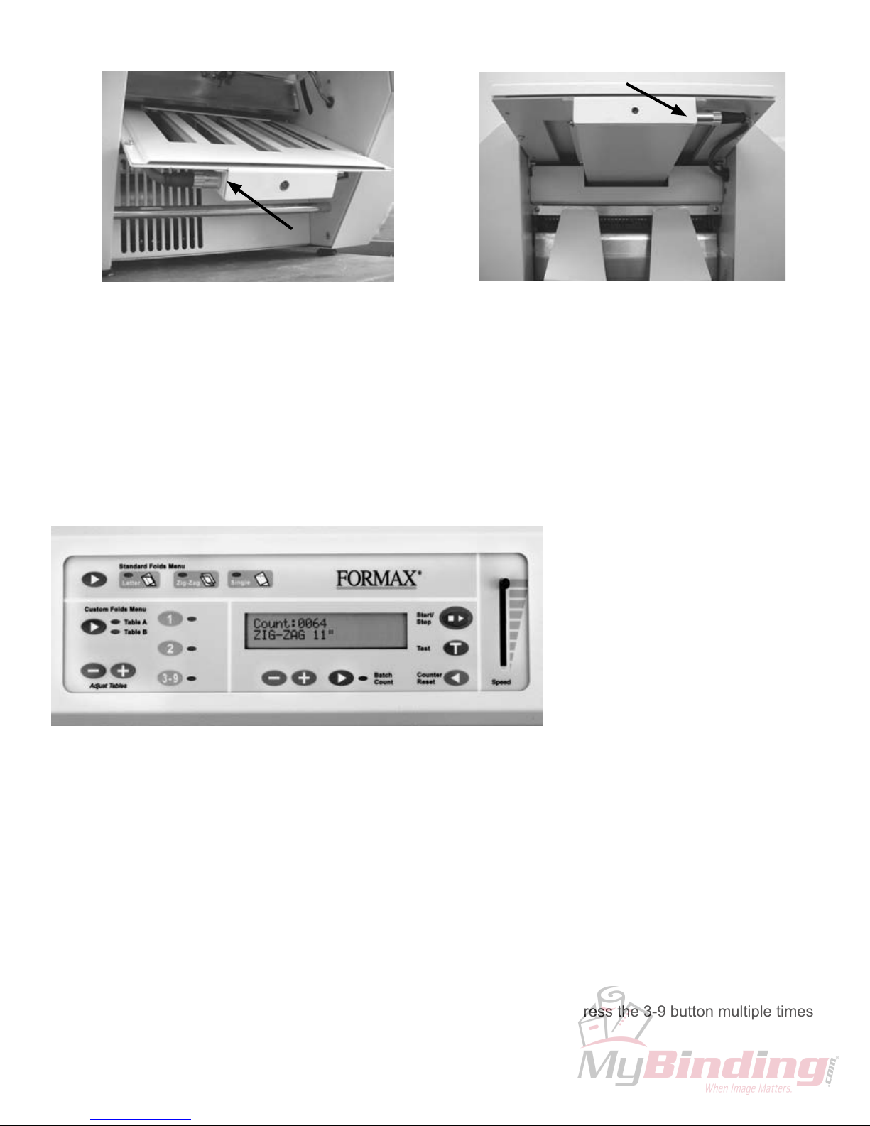
1. To enter the manual batch counting mode press the
“Batch Count” button and select “MANUBATCH” by
pressing the “+” button (Fig 3a) .
2. Select the number of sheets to be folded by pressing
the “+” or “-” buttons (Fig. 3b) , then press the “Start/
stop” button to start.
MANUBATCH:
The “Manubatch” or “manual batch” feature allows you to program the number of sheets you would like to
process in a set. When the set is complete the folder will stop and automatically reset the batch count to the
previously set number of sheets, it will then fold the next set when the “Start/Stop” button is pressed.
Fig. 3c
AUTOBATCHTM:
“Autobatch” or “automatic batch” allows you to batch count with automated features. In the Autobatch mode
you can program the number of sheets you would like to process in a set, the number of sets you would like
and the delay between each set. For example: you can program 10 sheets to be pulled to create a set, then
program 100 sets to be processed with a 3 second time delay between each set.
1. To enter the Autobatch mode press the “Batch
Count” button and select “AUTOBATCH” by pressing
the “-” button (Fig 3a).
2. Once you have entered the Autobatch mode press
the “+” or “-” button and “Sheets”(Fig. 3c) will blink.
Press the “+” or “-” buttons to increase or decrease the
number of sheets to be pulled.
3. When the sheet number is set wait 5 seconds and
“Sets” (Fig. 3c) will blink. Press the “+” or “-” buttons to
increase or decrease the number of sets to be pulled.
4. When the number of sets has been selected wait 5
seconds and “Delay” (Fig. 3c) will blink. Press the “+”
or “-” buttons to increase or decrease the time delay
between the sets.
5.When the settings are correct press the “Start/Stop”
to start.
NOTE: The system will cycle through the settings until
the “Start/Stop” button is pressed.
NOTE: If a fault occurs during a set the set will be
completed when the fault is reset.
NOTE: The batch counting program selected will
remain on after the job is processed. You must press
the Batch Counting button to turn off the light and
cancel the batch count setting.
“Sheets” = Number of sheets of paper in a set
“Sets” = Number of sets to be processed
“Delay” = Time between each set
“C” = Total number of sheets processed
Batch Counting with chip rev. 4.08
Fig. 3a
Fig. 3b

6
DAILY MAINTENANCE
1. It is recommended to let forms cool for one-half hour, from the laser printer, before folding. This allows
toner to set on the forms and static electricity to discharge. The FD 400 Jogger is recommended for best
results. The Jogger squares the forms and dissipates heat and static created by laser printers.
2. Clean infeed tires, fold rollers and two metal sealer rollers with Formax recommended roller cleaner &
rejuvenator to remove paper dust and toner. A Formax Cleaner Kit is available from your dealer. A damp
cloth with water is the best alternative.
CAUTION: Do not use any chemicals other than the roller cleaner & rejuvenator or water.
1. Make sure machine is turned off and unplugged. All
folder/sealers have three infeed tires, four rubber fold
rollers and two metal sealer rollers .
2. Lift top covers and remove the upper and lower fold
plates.
3. Using Formax roller cleaner, spray a new cotton
cloth until the cloth is saturated. Wipe the wet cloth
in a back and forth motion making sure to clean
the entire surface of the infeed tires, fold and seal
rollers. Now take a dry cloth and wipe off excess
toner. The cloth should be covered with black toner
surplus from cleaning the rollers.
4. Make sure to run 10-15 sheets of blank copy paper
to ensure all cleaner has been removed from the
tires and fold rollers. Running blank sheets will
remove any excess residue of cleaner on the rollers.
CLEANING PROCEDUERS:
infeed tires Fold Rollers
Sealer Rollers

SEALER ROLLER CLEARANCE
TO REPLACE INFEED ROLLERS
MAINTENANCE
To adjust roller clearance for the steel sealer rollers,
first loosen locking nuts on the top plates and insert
the feeler gauge (0.001”) into the space between
the rollers. Adjust the clearance between rollers to a
light drag on the high spot of the steel rollers. Tighten
locking nuts on both sides while holding the adjusting
bolt. Recheck and adjust as required.
NOTE: (Double-check spacing with feeler gauge. Left
to right fine-tuning is required.)
1. Turn power off and unplug the power cord.
2. Open top covers and remove non-operator side cover.
3. Loosen thumbscrew inside top cover.
4. Pull up clamp.
5. Remove “E” ring on gear. (See Folder Roller)
6. Remove gear and chain. (See Folder Roller)
7. Loosen individual rollers (one screw each)
8. Pull roller bar through each roller in the direction of the removed gear.
9. To reassemble, repeat above steps in reverse.
ADJUSTING THE GATE
To adjust the gate tip. Unplug machine and remove lower fold table. Turn tee knob (item 15, page 22)
counter clockwise until gate singulator pad (item 11 page 22) touches the feed wheel (item 29 page
21) continue adjusting until a moderate drag is felt between the gate tip singulator and the infeed
wheel, if double feeding occurs increase drag.
7

TO REPLACE SINGULATOR PAD
1. Remove in-feed rollers (page 7).
2. Remove rubber singulator pad, a screwdriver or knife may be needed to pry the pad off.
3. Clean singulator mount.
4. Apply super glue to singulator pad and singulator mount.
5. Apply singulator pad to singulator mount, let sit for at least five minutes before reinstalling in-feed rollers.
6. Reinstall in-feed rollers.
Singulator Pad
1. Lower in-feed tray.
2. Remove old cork pad, a screwdriver or knife may be needed to pry the pad off.
3. Clean area of removed pad.
4. Apply super glue to cork pad and in-feed tray.
5. Apply cork pad to in-feed table. Let sit for at least five minutes before operating the machine.
TO REPLACE CORK PAD
Cork Pad
8

TO REPLACE SEALER ROLLERS
1. Turn power off and unplug power cord.
2. Remove side covers and upper fold plate.
3. Remove belts. (See belt replacement, pg 10.)
4. Remove top plates by unscrewing four screws.
5. Loosen or remove the five lower screws on each side.
6. Remove first roller by lifting up and out of machine.
7. Remove the two springs.
8. To remove second roller tilt stainless steel center away from roller.
9. Remove second roller the same way as the first roller.
10. To reassemble, repeat above steps in reverse.
11. Adjust belt tension. (See belt replacement, pg 10.)
1. Turn power off and unplug power cord.
2. Remove side covers and upper fold plate.
3. Remove control panel.
4. Remove belts. (See belt replacement, pg 10.)
5. Remove “C” and “E” rings on gears and sprocket.
6. Remove sprocket and chain.
7. Remove plastic gears.
TO REPLACE FOLDER (RUBBER) ROLLERS
9

8. Remove bearing by unscrewing the two screws on each bearing assembly (same side as plastic gears).
9. Remove the six screws for the guide panel.
10. Proceed to pull out the desired folder roller.
11. To reassemble, repeat above steps in reverse.
BELT ADJUSTMENT AND REPLACEMENT
NOTE: Roller clearance must be set before adjusting belt tension.
To replace belt loosen screw on the side of lever until belt is loose enough to remove.
To adjust belt first determine if belt is too tight, or too loose (belt should have no more than 5/16” play). Tighten
or loosen the screw on the side of lever. (See arrow in above picture.)
NOTE: Be sure not to over tighten belt, it will affect roller clearance.
PHOTO EYE REPLACEMENT
1. To replace the photo eye, loosen the screw on the guide plate. Carefully remove the screw and photo eye.
2. Unplug the wires and discard old photo eye.
3. Reverse the previous step to install the new photo eye.
4. Adjust the photo eye so it sits 1/8” below the guide plate, then tighten the screw to insure the photo eye does
not move.
10

1. Sensor Test Mode
This mode is used to verify the inputs from various sensors on the machine and check the
operation of the machine speed control.
1. Turn the power switch on while pressing the Table A/B Select button.
2. Release the Table A/B Select Button when all of the lights on the display light up.
3. The display screen will show “Revision” followed by the revision number.
4. The display will then show “Resetting table positions...” while the fold tables reset.
5. The top line of the display will then indicate which sensors are activated
6. The bottom line of the display will show “SPEED” followed by the percentage setting of the speed
control.
NOTE: Once you leave a step and go to the next step you can not go back to the previous step.
2. Controls Test Mode
This mode is used to verify the inputs on the control panel of the machine and to check the
operation of the infeed clutch.
1. From Sensor Test Mode press and release any button on the control panel.
2. The bottom line of the display will show “SPEED” followed by the percentage setting of the speed
control as it does in Sensor Test Mode.
3. The top line will indicate the last button that was pressed.
NOTE: If “Table A/B” button is pressed and immediately released the machine will exit Diagnostic Mode.
4. To verify the operation of the infeed clutch simultaneously press and hold the Test button and
manually turn the infeed rollers in the overhand direction. If the rollers lock the clutch is working
properly.
3. Fold Table Offset Adjustment
This function is used to adjust the standard fold settings on the fold tables.
1. From the Controls Test Mode press and hold the Table A/B button until the machine enters the
Fold Table Offset Adjustment function.
2. The display will show “Fold Table Offset” and “Tbls. A: B:”. “A:” and “B:” will be followed by the
offset value.
3. To change an offset value toggle to the desired fold table using the Table A/B button and use the
custom Plus and Minus buttons to set the offset up or down.
4. The adjustments can be tested by pressing the Test button. This will reset the fold tables and
position them to a 11” Letter fold setting. The machine will then feed a single sheet for fold
verification.
5. To save adjustments press and hold the Table A/B button until the sound of the beep. The
RUNNING DIAGNOSTIC TESTS
Diagnostic tests prior to chip rev. 4.08:
The diagnostic software runs tests on the mechanical and electrical functions of the folder/sealer to make sure
they are functioning properly. The diagnostic mode is also used to set and/or verify offsets.
11
To enter the diagnostic mode press and hold the “Custom Fold” green arrow button and turn the
machine on. Continue to press the green arrow button until “Diagnostic Mode” appears on the screen.
The following tests will be able to be performed.

5. To save adjustments press and hold the Table A/B button until the sound of the beep. The
machine then returns to the standard operation mode.
6. Use the following legend as a guide for the Fold Table Offset Adjustment function:
Button Operation
“Test” button resets the fold table and positions them to a 11” Letter setting using the
displayed offset values.
“Plus” button (Custom) increments the offset value for the selected fold table.
“Minus” button (Custom) decrements the offset value for the selected fold table.
“Table A/B” button press and hold from Controls Test Mode to access Fold Table Offset
Function.
“Table A/B” button press and release within Fold Table Offset Function to toggle between table
A and B.
“Table A/B” button press and hold Fold Table Offset Function till sound, to store offset
adjustments.
7. To exit Fold Table Offset Function without saving adjustments turn the power switch off.
12

To enter the diagnostic mode press and hold the “Custom Fold” green arrow button and turn the
machine on. Continue to press the green arrow button until “Diagnostic Mode” appears on the screen.
The following tests will be able to be performed.
1. Sensor Test
This mode is used to verify the inputs from various sensors on the machine including paper length, width and
multi-feed sensors.
1. “Check Sensors” “No-” “Yes+” will appear on the screen.
2. Press the “Batch Count” “-” button to select no or the “Batch count” “+” button to select yes.
3. To test the paper out switch press the switch down, to test the 14” paper length and exit sensors run a piece
of white paper over the photo-eyes and to test the 17” paper sensor move the side guides out.
4. After the check has been performed press the “Batch Count” green arrow button to advance to the next test.
2. Button Test
This mode is used to verify that the control panel buttons are working.
1. “Check Buttons” “No-” “Yes+” will appear on the screen.
2. Press the “Batch Count” “-” button to select no or the “Batch Count” “+” key to select yes.
3. If yes is selected press each button to verify that they are working properly.
4. After the check has been performed press the “Batch Count” green arrow button to advance to the next
test. NOTE: the arrow button has to be held down to advance as a test will be performed on the “Batch
Count” button first.
3. Speed Pot Test
This mode is used to verify the speed percentage.
1. “Check Speed Pot” “No-” “Yes+” “Speed = _%” will appear on the screen.
2. Press the “Batch Count” “-” key to select no or the “Batch Count” “+” key to select yes.
3. If yes is selected slide the speed control lever up and down to verify speed percentage.
4. After the check has been performed press the “Batch Count” green arrow key to advance to the next test.
4. Encoder Test and Adjustment
This mode is used to verify that the fold plate encoder is working properly.
1. “Check Encoders” “No-” “Yes+” will appear on the screen.
2. Press the “Batch Count” “-” key to select no or the “Batch count” “+” key to select yes. If yes is selected
“Top = __ Bot = __” will appear on the screen “Top” = Top fold plate, “Bot” = Bottom fold plate).
3. To make adjustment turn the fine tuning knob.
4. When the adjustment has been made press the “Batch Count” green arrow to save.
5. After the check has been performed press the “Batch Count” green arrow key to advance to the next test.
5. Fold Plate Test
This mode checks to see that the fold plate sensore are working properly.
1. “Test Fold Plates” “No-” “Yes+” will appear on the screen.
2. Press the “Batch Count” “-” key to select no or the “Batch Count” “+” key to select yes.
3. “Press the Wait to Advance Each Step” appears on screen press the “Batch Count” green arrow to
advance.
Diagnostic tests with chip rev. 4.08
13

4. Fold plates will move to the home position, “Top Encoder =__ Bottom Encoder=__” will appear on screen.
5. Press the “Batch Count” green arrow and the fold plate will adjust to extents, “Top Encoder__=Botttom
Encoder=__” will appear on screen.
6. Press the “Batch Count” green arrow and the fold plate will find home position again, “Top Encoder =__
Bottom Encoder=__” will appear on screen.
7. “Check Again” “No-” “Yes+” will appear on screen. Press the “Batch Count” “-” button to select no or the
“Batch count” “+” button to select yes.
6. Fold Plate Cycle Test
This mode checks to see that the fold stop worm gear is operating smoothly.
1. “Cycle Fold Plates” “No-” “Yes+” will appear on screen.
2. Press the “Batch Count” “-” button to select no or the “Batch count” “+” button to select yes.
7. Light Test
This mode is used to verify that the lights are working on the control panel.
1. “Check Lights” “No-” “Yes+” will appear on the screen.
2. Press the “Batch Count” “-” key to select no or the “Batch Count” “+” key to select yes.
3. If yes is selected “Off-” “On+” will appear on the screen.
4. Press the “Batch Count” “+” to illuminate the lights on the control panel.
5. Press the “Batch Count” “-” key to turn the light off.
6. After the check has been performed press the “Batch Count” green arrow key to advance to the next test.
8. Motor Test
This mode is used to verify that the motor is working properly.
1. “Check Motor” “No-” “Yes+” will appear on the screen.
2. Press the “Batch Count” “-” key to select no or the “Batch Count” “+” key to select yes.
3. If yes is selected “Off-” “On+” will appear on the screen.
4. Press the “Batch Count” “+” to turn the motor on.
5. Press the “Batch Count” “-” key to turn the motor off.
6. After the check has been performed press the “Batch Count” green arrow key to advance to the next test.
9. Clutch Test
This mode is used to verify that the feed tire clutch is working properly.
1. “Check Clutch” “No-” “Yes+” will appear on the screen.
2. Press the “Batch Count” “-” key to select no or the “Batch Count” “+” key to select yes.
3. If yes is selected “Off-” “On+” will appear on the screen.
4. Press the “Batch Count” “+” to engage the clutch, then turn the feed tires counter-clockwise tension should
be felt indicating the clutch is engaged .
5. Press the “Batch Count” “-” to disengage the clutch, then turn the feed tires counter-clockwise, there should
be no tension felt, indicating the clutch is disengaged.
6. After the check has been performed press the “Batch Count” green arrow key to advance to the next test.
10. Life Count
Shows the total number of sheets of paper run through the machine.
14

11. English and Metric
This feature changes the settings of the folder to read standard measurments or metric measurements.
1. “Select Paper Type English- Metric+” will appear on the screen.
2. Press the “Batch Count” “-” English to select no or the “Batch Count” “+” key to select Metric.
3. Press the “Batch Count” Green arrow to continue.
12. Fold Table Offset Adjustment
This function is used to adjust the standard fold settings on the fold tables
1. “Fold Table Offsets” “No-” “Yes+” will appear on the screen.
2. Press the “Batch Count” “-” key to select no or the “Batch Count” “+” key to select yes.
3. If yes is selected “Press TEST for Test” and “Top = __ Bot = __” will appear on the screen.
4. Press the “Custom Folds” green arrow to select “Table A”, or “Table B” (Table A = “Top” and Table B = “Bot”,
use the “Batch Count” “+” or “-” buttons to set the offset up or down.
5. Then Press the “Test” button to verify the settings (Note: If “Table A” is selected the 11” Single Fold will be
tested if “Table B” is selected the 11” Letter Fold will be tested.)
6. The machine will then feed a single sheet for fold verification.
7. Press the “Batch Count” green button after changes have been made.
8. “Save Changes” “No-” “Yes+” appears on the screen, press the “Batch Count” “-” key to select no or the
“Batch Count” “+” key to select yes.
9. After the adjustment has been performed press the “Batch Count” green arrow key to advance to the next
test.
13. Single Fold Diverter Offset Adjustment
This function is used to adjust the diverter setting for the Single Fold.
Factory preset, not to be adjusted in the field. Call for technical support.
15

TROUBLESHOOTING
1. If paper folds left or right adjust the skew adjuster. To adjust the skew, turn it left or right until the paper is
feeding correctly and folds squarely.
B. Paper Pulls Left or Right During Feeding:
WARNING: Turn off machine and unplug cord from its receptacle
1. If a jam occurs in a fold table, unplug and remove the fold table and remove paper. Reinstall and plug in fold
table and then press the counter reset button on the control panel to clear the fault signal.
2. If a jam occurs between the metal rollers, open the top cover, unplug and remove the upper fold table.
In machines with serial numbers prior to 2098, remove the one-way jam-clearing handle (located under
operator side cover), apply the handle to the lower roller and turn counter-clockwise until the paper jam is clear.
NOTE: The jam handle only works in the counter-clockwise rotation. Remove the jammed form and reinstall
and plug in the upper fold table, close the top cover, then press the counter reset button on the control panel to
clear the fault signal. WARNING: Put the jam clearing handle back, and close the side door before operating.
In machines with serial numbers 2098 and higher, remove the jam clearing tool (located under the upper fold
table), apply the tool to the upper metal roller (see photo), and turn clockwise until the paper jam is clear.
NOTE: Do not turn counter-clockwise and force the forms to exit machine as rollers may be damaged. Remove
the jammed form, return tool to holder and reinstall upper fold table. Reinstall cover and press reset button.
A. Clearing Paper Jams and Fault Signals on the Display Panel:
1. Adjust the side guides to the edge of the forms.
2. Clean the 3 infeed wheels with a cloth dampened with a mild household cleaner.
C. Skewed Forms
2. Side guides should be adjusted so that the forms do not have free play between the guides.
16
Machines with serial numbers prior to 2098 Machines with serial numbers 2098 and higher

D. Machine Plugged in, no Power:
1. Turn machine on.
2. Check wall outlet.
3. Press the circuit breaker.
4. If the display screen on the control board is not on, check the green power light on the power board. To view
the green power light, open the operator side cover and look though the air slots in view of the power board. If
that light is on, there’s a loose wire or connector not connected.
E. Power on, Machine does not Work:
1. If the green power light is not on at the power board check the circuit breaker. Then troubleshoot back to
where you have power.
2. If the display screen reads “COVER OPEN”, ensure that the operator and top covers are closed properly.
3. If the display screen reads “PAPER OUT”, load paper into hopper.
4. If the display screen reads “FAULT”, the photo eye has detected the presence of paper for more than half a
second. Remove the jammed paper, then press the counter reset button to reset the fault. If there is no paper
jam, check for proper operation of the photo eye.
F. Photo Eye Adjustment:
There is a single photo eye, just upstream from the pressure rollers. It is used for both counting and fault
detection (doubles). There is another photo eye, at the end of the paper tray extension. This is used for
detecting 11” paper or 14” paper. There are 2 sets of lights that will allow you to adjust the sensitivity of the
photo eyes.
The first set of lights on the left is used to adjust the photo eye sensitivity, for the fault detection. There are
three lights to help you do this. The first light is red (low signal). The second light is green (good signal). The
last light is red (excess signal). These lights can be viewed by opening the operator side cover.
The second set of lights on the right is used to adjust the photo eye sensitivity, for the paper detection. There
are three lights to help you do this. The first light is red (low signal). The second light is green (good signal).
The last light is red (excess signal). These lights can be viewed by opening the operator side cover.
The photo eyes can be adjusted using the two small blue square boxes on the control board. They have screw
slots in them for delicate adjustment. The first one on the left is for fault detection and the second one to the
right is used for 14” paper detection. To adjust, place a form on top of the photo eye and change the setting on
the small blue box until the red light (excess signal) just turns to the green light (good signal).
G. Misfeeding of Forms:
1. Clean the feeder wheels.
2. Adjust the skew adjust.
3. Turn forms upside down and rotate 180 degrees and place in hopper (Z” fold forms only).
17
H. Double Feeding:
If double feeding occurs try these following steps.
1. Jog the forms to reduce static build up and to make sure the forms are not stuck together.
2. Clean the infeed wheels with a cloth dampened with a mild household cleaner.
3. Ask the technician to adjust the gate tip.
Table of contents
Other Formax Food Saver manuals