PROGRAMMING PROCEDURE 1/2 | PROCÉDURE DE PROGRAMMATION 1/2
Parts required (not included) Pièces requises (non incluses)
1x
1x
software
1x Microsoft Windows Computer with
Internet connection
FLASH LINK UPDATER
FLASH LINK 3.52
2
MANAGER MIN
1x
1x Programme
1x Ordinateur Microsoft Windows avec
connection Internet
FLASH LINK UPDATER
FLASH LINK 3.52
2
MANAGER MIN
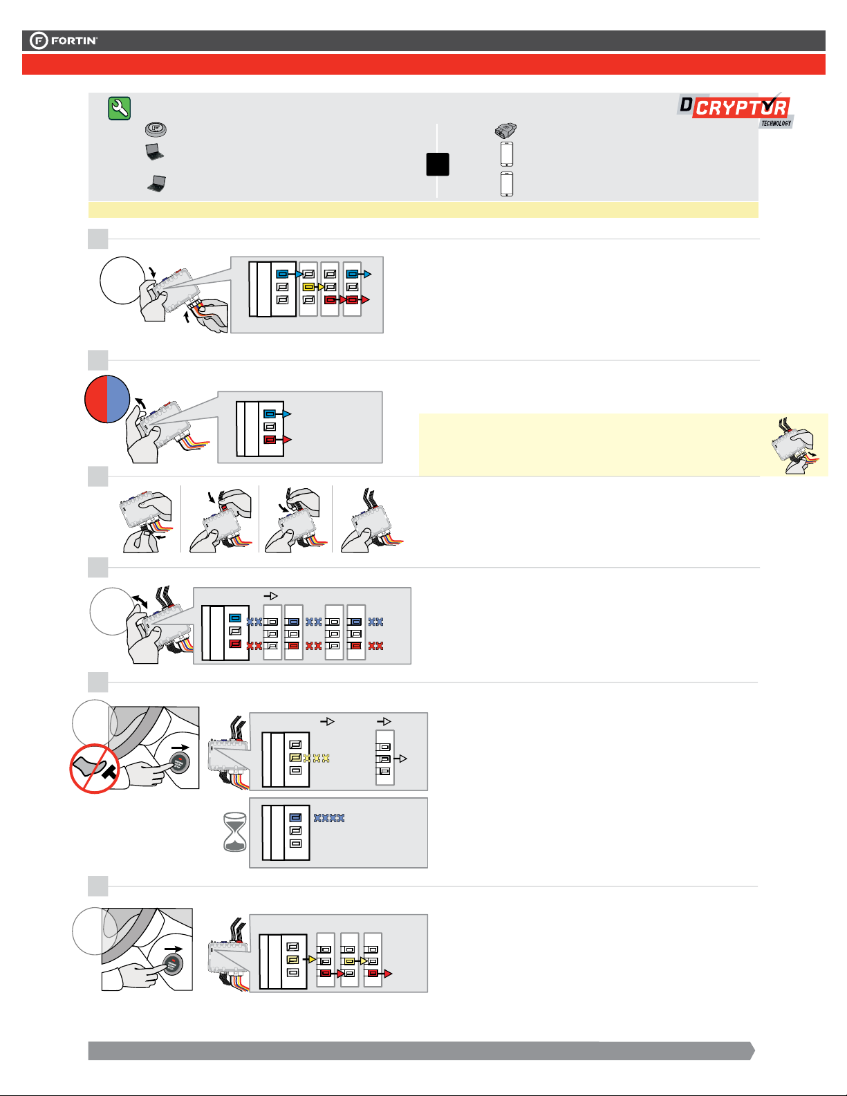
4
CONTINUE TO THE NEXT PAGE | CONTINUEZ À LA PAGE SUIVANTE
5
Press and release the
programming button three
times (3x).
x
3
PRESS
Appuyez et relâchez 3 fois le
bouton de programmation.
LOCK
ACC ON
PUSH
START
IGN
OFF
FLASH
IGNITION ON
FLASH
OFF
FLASH
RAPIDLY
The Red and Yellow LEDs
will start flashing alternatively.
Les DELs Rouge et Jaune
clignoteront alternativement.
LOCK
ACC ON
PUSH
START
OFF
PRESS X3
Honda Accord 2014 KEY
Honda Accord 2014 PTS
(MEME PORG. SAUFBOUTON)
Honda Odyssey 2014 PTS
1
2
RELEASE
3
ON BLUE
BLEU
ON RED
ROUGE
...
...
2XFLASHPAUSE PAUSE ...
ALTERNATE | ALTERNE
6
Tournez la clé à Ignition.
Turn the key to the
Ignition ON/RUN position.
Turn the key to the
OFF position.
Tournez la clé à la
position Arrêt (OFF).
Release the programming
button when the Blue & Red
LEDs are ON.
Relâchez le bouton de
programmation quand les
DELs Bleue & Rouge sont
allumées.
Si les DELs Bleue & Rouge ne sont
pas allumées, débranchez le
harnais Data-Link à 6-Broches et
retournez au début de l'étape 1.
If the Blue & Red LEDs are
not ON solid disconnect the
6-PIN Data-Link and go
back to step 1.
Connect the required
remaining harnesses.
Branchez les harnais requis
restants.
The Red and Blue LEDs
will alternate between 2
flashes and a pause.
Les DELs Bleue et Rouge
alterneront entre 2
clignotements et 1 pause.
Wait for the Yellow Led to
flash rapidly.
Attendez que la DEL Jaune
clignote rapidement.
Wait for the Blue LED to
flash rapidly.
Attendez que la DEL Bleue
clignote rapidement.
x
1
HOLD
LED may differ depending on the module casing.
L’apparence des DELS peut différer selon le boîtier du module.
Press and hold the
programming button:
Connect
the 6-PIN Main
harness (White connector).
The Blue, Red, Y
Blue & Red LEDs will
alternatively illuminate.
Appuyez et maintenir le bouton
de programmation enfoncé:
Branchez le harnais Principal à
6-Pins (connecteur Blanc)
Les DELs Bleue, Rouge,
Jaune et Bleue & Rouge
s'illumineront alternativement.
PROGRAMMING PROCEDURE 2/2 | PROCÉDURE DE PROGRAMMATION 2/2
Do not press the brake
pedal.
Press the Push-to-Start
button twice to turn on
the ignition.
IGN ON
x
2
PRESS
Ne pas appuyer sur la pédale
de frein.
Appuyez 2 fois sur le bouton
démarrage (Push-to-Start)
pour allumer l'ignition.
OFF
Press the Push-to-Start
button once to turn off the
ignition.
xx11
PRESS
Appuyez 1 fois sur le
bouton démarrage (Push-
to-Start) pour éteindre
l'ignition.
BLUE LED will turn off.The s'éteintLa DEL BLEUE
CAN-Bus programmed. Réseau CAN programmé.
FLASH LINK
UPDATER 2
FLASH LINK MANAGER
SOFTWARE | PROGRAMME
Date: xx-xx
HARDWARE VERSION : 3
FIRMWARE VERSION : 4.0+
Service No : 000 102 04 2536
INTERFACE MODULE
Made in Canada
PATENTS PENDING US: 2007-228827-A1
www.fortinbypass.com
EVO
A
E
F
GJ
I
H
B
C
D
Date: xx-xx
HARDWARE VERSION : 3
FIRMWARE VERSION : 4.0+
Service No : 000 102 04 2536
INTERFACE MODULE
Made in Canada
PATENTS PENDING US: 2007-228827-A1
www.fortinbypass.com
EVO
Microsoft Windows
Computer with
Internet connection
Ordinateur Microsoft
Windows avec
connection Internet
Pièces requises (non incluses)
Reconnect the 6-Pin Main connector
and all the remaining connectors.
Rebranchez le connecteur Principal à 6-broches
et ensuite tous les connecteurs restants du EVO-ONE.
Connect the module to the
FLASH LINK UPDATER 2
and visit the DCryptor menu
in the Flash-Link Manager .
Branchez le module au
FLASH LINK UPDATER 2
et visitez le menu DCryptor
dans le Flash-Link Manager.
Disconnect all EVO-ONE connectors.
Débranchez tous les connecteurs du EVO-ONE.
REMOTE STARTER / ALARM VERIFICATION
PROCEDURE | PROCÉDURE DE VÉRIFICATION
DU DÉMARREUR À DISTANCE / ALARME
The module is now programmed.
Le module est programmé.
Parts required (not included)
7
9
8
Test the remote starter. Remote start the vehicle.
Testez le démarreur à distance. Démarrez le véhicule à
distance.
3.52
MIN
PROGRAMMING PROCEDURE 2/2 | PROCÉDURE DE PROGRAMMATION 2/2
Do not press the brake
pedal.
Press the Push-to-Start
button twice to turn on
the ignition.
IGN ON
xx22
PRESS
Ne pas appuyer sur la pédale
de frein.
Appuyez 2 fois sur le bouton
démarrage (Push-to-Start)
pour allumer l'ignition.
OFF
Press the Push-to-Start
button once to turn off the
ignition.
x
1
PRESS
Appuyez 1 fois sur le
bouton démarrage (Push-
to-Start) pour éteindre
l'ignition.
BLUE LED will turn off.The s'éteintLa DEL BLEUE
CAN-Bus programmed. Réseau CAN programmé.
FLASH LINK
UPDATER 2
FLASH LINK MANAGER
SOFTWARE | PROGRAMME
Date: xx-xx
HARDWARE VERSION : 3
FIRMWARE VERSION : 4.0+
Service No : 000 102 04 2536
INTERFACE MODULE
Made in Canada
PATENTS PENDING US: 2007-228827-A1
www.fortinbypass.com
EVO
A
E
F
GJ
I
H
B
C
D
Date: xx-xx
HARDWARE VERSION : 3
FIRMWARE VERSION : 4.0+
Service No : 000 102 04 2536
INTERFACE MODULE
Made in Canada
PATENTS PENDING US: 2007-228827-A1
www.fortinbypass.com
EVO
Microsoft Windows
Computer with
Internet connection
Ordinateur Microsoft
Windows avec
connection Internet
Pièces requises (non incluses)
Reconnect the 6-Pin Main connector
and all the remaining connectors.
Rebranchez le connecteur Principal à 6-broches
et ensuite tous les connecteurs restants du EVO-ONE.
Connect the module to the
FLASH LINK UPDATER 2
and visit the DCryptor menu
in the Flash-Link Manager .
Branchez le module au
FLASH LINK UPDATER 2
et visitez le menu DCryptor
dans le Flash-Link Manager.
Disconnect all EVO-ONE connectors.
Débranchez tous les connecteurs du EVO-ONE.
REMOTE STARTER / ALARM VERIFICATION
PROCEDURE | PROCÉDURE DE VÉRIFICATION
DU DÉMARREUR À DISTANCE / ALARME
The module is now programmed.
Le module est programmé.
Parts required (not included)
7
9
8
Test the remote starter. Remote start the vehicle.
Testez le démarreur à distance. Démarrez le véhicule à
distance.
3.52
MIN
Do not press the brake pedal.
Press the Push-to-Start button
twice to turn ON the ignition.
Press the Push-to-Start button
once to turn OFF the ignition.
Ne pas appuyer sur le pédale de
frein.
Appuyez 2 fois sur le bouton démar-
rage (Push-to-Start) pour allumer
l’ignition.
Appuyez 1 fois sur le bouton démar-
rage (Push-to-Start) pour éteindre
l’ignition.
This guide may change without notice. See www.fortin.ca for latest version.
Ce guide peut faire l’objet de changement sans préavis. Voir www.fortin.ca pour la récente version.
DCRYPTOR PROGRAMMING PROCEDURE |PROCÉDURE DE PROGRAMMATION AVEC DCRYPTOR
Parts required (not included) Pièces requises (non incluses)
1x FLASH LINK UPDATER,
1x FLASH LINK MANAGER
1x FLASH LINK MOBILE
1x FLASH LINK MOBILE APP
SOFTWARE | PROGRAMME
Smartphone Android or iOS with Internet connection
(Internet provider charges may apply)
Téléphone Intelligent Android ou iOS avec connection
Internet (des frais du fournisseur Internet peuvent s’appliquer)
OR
OU
Microsoft Windows Computer with Internet connection
Ordinateur Microsoft Windows avec connection Internet
1x1x
BEFORE PROGRAMMING SET THE UNIT OPTION AND SAVE. | AVANT LA PROGRAMMATION CONFIGURER LES OPTIONS DE L'UNITÉ ET SAUVEGARDER.
Page 7 / 10