Forza FDC-106K User manual

2-year
Warranty
User Manual
Uninterruptible Power Supply System
FDC-106K / FDC-110K

1. Introduction
1.1 Transportation and storage
1.2 Preliminary steps
1.3 Initial setup
1.4 Important safety instructions
1.5 Standards
2. Installation and operation
2.1 Unpacking and inspection
2.2 UPS front and rear panel views
2.3 Single UPS installation
2.4 Output configuration
2.5 ForzaTracker monitoring software
3. Advanced operation
3.1 Description of buttons and functions
3.2 LED indicators and LCD panel
3.3 Audible alarm
3.4 Single UPS operation
3.5 Parallel operation
3.6 Abbreviations in the LCD display
3.7 UPS parameter settings
3.8 Operating mode/Status description
3.9 Fault codes
3.10 Warning indicators
4. Troubleshooting guide
5. Storage and maintenance
6. Technical specifications
Table of content
1. Introduction
Thank you for purchasing the Forza Atlas FDC 106K/110K Online UPS. To enjoy all the features and benefits of this unit,
please read and follow all installation and operation instructions thoroughly before unpacking, installing or operating this
device. After you have read this manual, keep it in a safe place for future reference.
The information contained in this manual covers the 6000VA and 10000VA uninterruptible power systems, their basic
functions, operating procedures, options available and troubleshooting guide. It also includes information on how to ship,
store, handle, and install the equipment.
1-1. Transportation and storage
• Transport the UPS system only in the original package to protect it against shock and impact.
• The UPS must be stored in a dry, well-ventilated area.
1-2. Preliminary steps
• Water condensation may occur if the UPS is unpacked in a very cold environment and then moved to a warmer
location.
• The UPS must be thoroughly dry before being installed. Failure to do so may increase the risk of electric shock.
• Do not install the UPS system near water or in moist environments.
• To reduce the risk of overheating, do not cover the cooling vents in the UPS housing.
• Avoid exposing the UPS to direct sunlight or installing the unit near heat-emitting appliances, such as electric heaters or
furnaces.
1-3. Initial setup
• Do not connect appliances or equipment that may overload the UPS system (such as big motor-type equipment) to the
UPS output sockets or terminal.
• Place cables in such a way that no one can step on or trip over them.
• Do not block air vents in the housing of UPS. The UPS must be installed in a location with good ventilation. Ensure enough
space on each side for ventilation.
• The UPS is provided with an earthed terminal. Equipotential earth bonding to the external UPS battery cabinets must
be provided if such configuration is used.
• The UPS can be installed only by qualified maintenance personnel.
• These UPS units are extremely heavy. Caution should be taken in moving and positioning equipment.
• An appropriate disconnect device as short-circuit backup protection should be provided in the building wiring installation.
• An integral single emergency switching device which prevents further supply to the load by the UPS in any mode of
operation should be provided in the building wiring installation
• Connect the earth before connecting the unit to the building wiring terminal.
• Installation and wiring must be performed in accordance with local electrical regulations and laws.
1-4. Important safety instructions
• Do not disconnect the earth conductor cable on the UPS or the building wiring terminals at any time since this would
cancel the protective earth of the UPS system and of all connected loads.
• In order to provide security and safety measures according to NFPA under 70 NEC article 250.20(D), the Neutral output is
internally grounded to the chassis of the UPS as a grounding system.
• The UPS system features its own, internal current source (batteries). The UPS output sockets or output terminals block
may be electrically live even if the UPS system is not connected to the building wiring outlet.
• In the event of an emergency, pull the EPO cable if in default mode or press the switch connected to the EPO if that option
is installed. Then disconnect the power from the AC mains to properly disable the UPS.
• Do not allow any kind of liquid or foreign object to enter this UPS unit. Do not place beverages or any other containers with
liquid on or nearby the unit.
• The UPS can be operated by any individuals with no previous experience.

1-5. Standards
2. Installation and operation
The Forza Atlas series is offered in two different models, as shown in the table below.
2-1. Unpacking and inspection
Remove the UPS from its package and make sure that all the following items are included:
• One UPS unit
• One user manual (digital copy in CD)
• One monitoring software CD (ForzaTracker)
• One USB cable
• Warranty certificate
Carefully inspect the UPS to check for any damages that may have occurred during shipping. Should any evidence of
damage be found or if some parts are missing, do not turn the UPS on; you must immediately notify the carrier or dealer
where you purchased the unit.
* Safety
IEC/EN 62040-1
* EMI
Conducted emission
Radiated emission
* EMS
ESD
RS
EFT
SURGE
CS
Power-frequency magnetic field
Low frequency signals
Warning: This product is intended for commercial and industrial applications.
Installation in the proper environment is required.
IEC/EN 62040-2
IEC/EN 62040-2
IEC/EN 61000-4-2
IEC/EN 61000-4-3
IEC/EN 61000-4-4
IEC/EN 61000-4-5
IEC/EN 61000-4-6
IEC/EN 61000-4-8
IEC/EN 61000-2-2
Category C3
Category C3
Level 4
Level 3
Level 4
Level 4
Level 3
Level 4
Model Capacity
FDC-006K
FDC-010K
6000 VA (6000 W)
10000 VA (10000 W)
2-2. UPS front and rear panel views
Front view
Rear panel diagram
6K/10K
Diagram 1:
Rear panel overview
Diagram 2:
Input/output terminal
12
11
10
15
7
1 2 3 54
6
8
9
17 13 14 16

1. RS-232 communication port
2. USB communication port
3. Emergency power off (EPO) connector
4. Parallel current port
5. Parallel data ports
6. Intelligent slot
7. Charger fan
8. Power stage fan
9. Maintenance bypass switch
10. Input circuit breaker
11. Isolation transformer fan
12. Input/output terminal (Refer to diagram 2 for details)
13. Output terminal 1
14. Output terminal 2
15. External battery connector
16. Utility input terminal
17. Non-isolated neutral terminal
2-3. Single UPS installation
Installation and wiring must be performed by qualified personnel, and in accordance with the local electrical regulations and codes.
Also, you must observe the following instructions:
1) Make sure the mains wire and breakers in the building are enough for the rated capacity of the UPS to avoid the hazards
of electric shock or fire.
Note: Do not use a wall receptacle as the input power source for the UPS, as its rated current is less than the UPS maximum
input current. Failure to do so may result in a broken or burned out receptacle.
2) For safety considerations, turn off the mains switch in the building before installation.
3) Turn off all the devices before connecting them to the UPS.
4) Wiring sizes should be installed in accordance with the following table:
Note 1: The cable for 6K should be able to withstand currents of over 40A. It is recommended to use a 10AWG or thicker wire
for safety and efficiency.
Note 2: The cable for 10K should be able to withstand currents of over 63A. It is recommended to use an 8AWG or thicker wire
for safety and efficiency.
Note 3: For single model, it is not necessary to connect the non-isolated neutral terminal.
Note 4: The color selection of wires should be made according to the local electrical codes and regulations.
5) Remove the terminal block cover on the rear panel of UPS. Proceed to connect the wires according to the following terminal
block diagrams: (Make sure to attach the earth wire first when connecting the wires. When removing the wiring, make sure to
remove the earth wire last).
Note 1: Make sure that the input and output wires and the input and output terminals are connected tightly.
Note 2: There are two output terminal configurations to meet customers’ diverse requirements for serial or parallel connection.
Please refer to section 2.4.
Note 3: Install the leak current protective breaker at the output power distribution panel of the UPS, if necessary.
6) Put the terminal block cover back in the rear panel of the UPS.
Warning:
• For safety considerations, switch all power off using the main switch before installation.
Note: The battery breaker must also be set to OFF before installing the battery pack.
• Pay close attention to the rated battery voltage marked on the rear panel. If you want to change the number of batteries, please
make sure you modify the settings accordingly. A connection with the wrong battery voltage may cause permanent damage to the
UPS. Make sure the voltage of the battery pack is correct.
• Pay close attention to the polarity markings on the external battery terminal block, and make sure to match the correct battery
polarity of the cells. Wrong connection may cause permanent damage to the UPS.
• Make sure the protective earth ground wiring is correctly installed. The wire current specification, color, position, connection and
conductance reliability should be checked carefully.
• Make sure the utility input and output wiring is correct. The wire current specification, color, position, connection and conductance
reliability should be checked carefully. Make sure the L/N wiring is correct, not reverse and short-circuited.
2-4. Output configuration
Option 1:
There are 2 sets of low-voltage outputs (104/110/115/120V) on L1-N1 and L2-N2. Each set is able to provide 50% of the UPS rated
current. Connect one load to L1-N1 and the other load to L2-N2.
Option 2:
After connecting L1-L2 and N1-N2, it becomes one low-voltage output (104/110/115/120V) at L1-N1 for 100% of the UPS rated
current. Connect load to L1-N1 or L2-N2.
Wiring specification (AWG)
Model Input GroundOutput Non-isolated
Neutral
6K
10K
10
8
10
8
10
8
10
8
Terminal block wiring diagram of 6K/10K
To load 1
To load 2
L 1 N1 L 2 N2 L N
To load
L 1 N1 L 2 N2 L N
Input neutral
Input line
Output 2 neutral
Output 2 line
Non-isolated neutral
Output 1 line
Output 1 neutral/ground

FunctionButton
ON/Enter
Button
OFF/ESC
Button
Test/Up
Button
Mute/Down
Button
Test/Up +
Mute/Down
Button
Turns on the UPS: Press and hold this button over 0.5 second to turn on the UPS.
Enter Key: Press this button to confirm the selected settings of the configuration menu.
Turns off the UPS: Press and hold this button for 0.5 second to turn off the UPS.
Esc key: Press this button to return to the last setting of the configuration menu.
Battery test: Press and hold this button for 0.5 second to test the battery status while
in AC mode, or CVCF mode.
UP key: Press this button to display the next selection in the configuration menu.
Mutes the alarm: Press and hold the button for 0.5 second to mute the buzzer.
Please refer to sections below for details.
Down key: Press this button to display previous selection in the configuration menu.
Press and hold these two buttons simultaneously for 1 second either to enter
or exit the menu settings.
•
•
•
•
•
•
•
•
•
3. Advanced operation
3-1. Description of buttons and functions
3-2. LED Indicators and LCD panel
There are 4 LEDs on front panel to show the UPS working status:
* CVCF stands for converter mode
Mode LED
UPS startup
No Output
Bypass mode
AC mode
Battery mode
CVCF mode
Battery Test
ECO mode
Fault
Bypass Line Battery Fault
BYPASS LINE BATTERY FAULT
LED indicators
Note: means LED is illuminated means LED is not illuminated
Option 3:
After connecting N1 and L2, it becomes one high-voltage output (208/220/230/240V) at L1-N2 for 100% of the UPS rated current.
Connect load to L1-N2.
Option 4:
After connecting N1 and L2, it becomes three outputs, one high-voltage output (208/220/230/240V) at L1-N2 and two low-voltage
outputs (104/110/115/120V) at L1-N1 and L2-N2. However, there is a limit for current rating at L1-N1 and L2-N2: 25A for 6K model
and 42A at 10K model. You must connect the load taking into account such limits. Please read the notes before installation.
Connect the low-voltage load to L1-N1 and L2-N2, and connect the high-voltage load to L1-N2.
Note 1: If any load current in L1-N1 or L2-N2 is higher than 25A in 6K model and 42A in 10K model, the UPS will still operate
normally without overload warning because the total load is under the specified limit. However, the high current can damage the
isolation transformer due to overheat caused by the high current. Hence, the installation must be done with a technician to ensure
that the load current will not exceed this limitation.
Note 2: When connecting to low-voltage and high-voltage at the same time as described in option 4, the L1-N1 and L2-N2 will feed
low-voltage loads in non-isolated status because high-voltage is being generated by shorting N1-L2. If keeping a connected load in
isolated status is required, we recommend that you may only use two low-voltages at L1-N1 or L2-N2 like illustrated in option 1, and
also make sure that the total current in L1-N1 or L2-N2 does not exceed the value specified in Note1.
2-5. ForzaTracker monitoring software
ForzaTracker is a new generation of UPS monitoring software, which provides user-friendly interface to monitor and control your
Uninterruptible Power System. This unique software provides safe auto-shutdown for multi-computer systems during power failures.
With this software, users can monitor and control any UPS on the same LAN no matter how far they might be from the UPS.
Installation procedure for Windows users:
1. Use the supplied CD or go to the website: http://www.forzaups.com/us/driver-downloads/.
2. After clicking the software icon, choose the required operation system.
3. Follow the on-screen instructions to install the software.
4. When you finished downloading all required files, enter the serial No (Installation Password): 5242-87f6-64re-di8d-986u to install
the software (include the hyphens).
To load
L 1 N1 L 2 N2 L N
To load 1
To load 2
To load 3
L 1 N1 L 2 N2 L N
5. In order to access as Administrator, input the password: 111296.
6. When your computer restarts, the management software will appear as a light blue round icon located in the system tray, near
the clock.
For Mac users, please refer to the ForzaTracker quick installation guide inside the Mac folder.
Display Function
Backup time information
Fault information
Mute operation
Output and battery voltage information
Load information
Mode operation information
Provides a digital indication of the battery discharge time.
H: hours M: minutes S: seconds
Indicates that a warning or fault has occurred.
Displays the fault codes, listed in detail in the sections below
Indicates that the UPS alarm has been disabled.
Provides an indication of the output voltage, frequency or battery
voltage.
VAC: output voltage VDC: battery voltage Hz: frequency
Indicates the load level at 0-25%, 26-50%, 51-75%, and 76-100%
Indicates the load or the output is short-circuited.
Overload indication.
Indicates that the UPS is connected to the mains.
Indicates the battery is in working status.

3-3. Audible alarm
3-4. Single UPS Operation
1. Turn on the UPS with utility power (On grid/ AC mode)
1) After making sure that the power supply connection is correct, set the input breaker to the “ON” position first. At this point,
the fan will start running while the UPS supplies power to the load via the bypass. The UPS is now operating in Bypass mode.
Note: When the UPS is in Bypass mode, the output voltage will directly power the load from utility after you have switched on
the input breaker. In Bypass Mode, the load is not protected by the UPS. To protect your load devices, you should turn on
the UPS as explained below.
2) Press and hold the ON button for 0.5 second to power on the UPS. The buzzer will beep once.
3) After a few seconds, the UPS will enter into the AC mode. In case of abnormal utility power, the UPS will transfer to battery
mode operation to provide uninterrupted power to the outlets.
Note: In battery mode, the UPS will shut down automatically when the remaining charge is low. Once the utility power is
restored, the UPS will restart automatically in AC mode.
2. Turn on the UPS without utility power (Battery mode)
1) Press and hold the ON button for 0.5 second to power on the UPS. The buzzer will beep once.
2) After a few seconds, the UPS will be turned on and begin operating on “off-grid” or Battery mode.
3. Connecting devices to the UPS
After the UPS is turned on, you can connect devices to the unit.
1) Turn on the UPS first and then start switching “on” one load at a time, only after all of them have been plugged into the unit.
The total load level will be displayed on the LCD panel.
2) Should you need to connect inductive loads, such as a monitor or a laser printer to the UPS, the start-up power should be
used for calculating the capacity of the UPS, as energy consumption increases during initial power on.
Description
UPS status
Bypass mode
Battery mode
Fault mode
Warning
Overload
Others
Fault
All
Buzzer status
Beeps once every 2 minutes
Beeps once every 4 seconds
Beeps continuously
Beeps twice every second
Beeps once every second
Beeps continuously
Yes
Yes
Yes
Muted
LCD panel:
Backup
Time Info
Mode Operation
Info
Programmable
Output Info
Input & Battery
Voltage Info
Output & Battery
Voltage Info
Battery Info Load Info
Fault
Info Mute Operation
Display Function
Backup time information
Fault information
Mute operation
Output and battery voltage information
Load information
Mode operation information
Battery information
Provides a digital indication of the battery discharge time.
H: hours M: minutes S: seconds
Indicates that a warning or fault has occurred.
Displays the fault codes, listed in detail in the sections below
Indicates that the UPS alarm has been disabled.
Provides an indication of the output voltage, frequency or battery
voltage.
VAC: output voltage VDC: battery voltage Hz: frequency
Indicates the load level at 0-25%, 26-50%, 51-75%, and 76-100%
Indicates the load or the output is short-circuited.
Overload indication.
Indicates that the UPS is connected to the mains.
Indicates the battery is in working status.
Indicates the bypass circuit is in working status.
Indicates the ECO mode is enabled.
Indicates the output connector is working properly.
Indicates the inverter circuit is working.
Battery information
Input and battery voltage information
Indicates the output connector is working properly.
Indicates the battery is charged at 0-25%, 26-50%, 51-75%, and
76-100% of its capacity.
Indicates the battery is not connected.
Low battery and low voltage indicator.
Indicates the input voltage or frequency, or battery voltage.
VAC: input voltage VDC: battery voltage Hz: input frequency
Indicates the inverter circuit is working.

3) If the UPS is overloaded, the buzzer will beep twice every second.
4) In the event of an overload, all unnecessary loads must be removed one by one, to lower the total loads connected to the
UPS to less than 80% of its nominal power capacity to prevent overload condition.
5) If the overload time exceeds the time specified in AC mode, the UPS will automatically transfer to Bypass mode. After the
overload is removed, the UPS will return to AC mode. If the overload time exceeds the time specified in Battery mode, the
UPS will transfer to fault status. At this time, if bypass is enabled, the UPS will supply power to the loads using the bypass
mode. If the bypass function is disabled or the input power is not within the bypass acceptable range, the output power will
be cut off immediately.
4. Charging the batteries
1) Once the UPS is connected to utility power, the unit will charge the batteries automatically, except when the USP is running
in Battery mode or while the battery self-test is in progress.
2) It is recommended to charge the batteries at least 10 hours before use to ensure proper backup time.
3) Make sure battery number setting on the control board is consistent with the actual connection.
5. Battery mode operation
1) When the UPS is in Battery mode, the buzzer will beep according to the battery capacity.
a. If the battery capacity is more than 25%, the buzzer will beep once every 4 seconds.
b. If the battery voltage drops to the alarm triggering level, the buzzer will beep once every second to indicate that the battery
has reached its lowest capacity, and that the UPS will soon shut down automatically. Shutting down non-critical loads at
this point will prolong the backup time. If the programmable timer function is enabled, the UPS will shut off programmable
output terminals automatically.
Note: There is the risk of data loss or load failure if battery runtime is exceeded.
2) To silence the buzzer sound in Battery mode, press the Mute button.
3) The backup time vary depending upon environment conditions and load types.
4) When the backup time is set at 16.5 hours (LCD panel default value), the UPS will shut down automatically to protect the
battery after the discharging period of 16.5 hours is completed. This battery discharge protection can be enabled or disabled
using the LCD panel control.
6. Testing the batteries
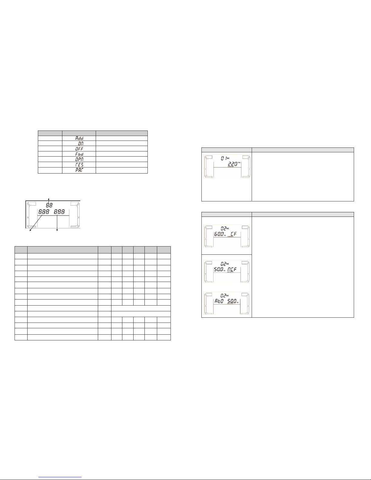
1) To check the battery status when the UPS is running in AC mode/CVCF mode/ECO mode, press the Test button to initiate
the self-diagnostic tool.
2) To maintain the system reliability, the UPS will perform an automatic battery self-test on a periodic basis. The default setting
for the battery self-test is once per week.
3) Battery self-test interval can also be set through the monitoring software.
4) When the UPS is in battery self-test mode, the LCD Display and buzzer indication will be the same as in battery mode, with
the exception that the battery LED will appear blinking in this case.
7. Turn off the UPS with utility power in AC mode
1) Turn off the inverter of the UPS by pressing the OFF button for at least 0.5 second. The buzzer will beep once and the UPS
will go into Bypass mode.
Note 1: If the UPS has been set to enable the bypass output, it will bypass voltage from utility power to the output terminal
even though the UPS (inverter) has been turned off.
Note 2: After turning off the UPS, please beware that the UPS is operating in Bypass mode and there is a risk of power loss
for connected devices.
2) In Bypass mode, output voltage of the UPS is still present. In order to shut off the output voltage, switch off the input breaker
to the UPS. A few seconds later, there will be no display shown on the LCD panel while the UPS is now completely turned
off.
8. Turn off the UPS without utility power supply in Battery mode
1) Turn off the UPS by pressing the OFF button for at least 0.5 second. The buzzer will beep once.
2) The UPS power will shut off output and there will be no indication showing on the display panel.
9. Muting the buzzer
1) To silence the buzzer, press the Mute button for at least 0.5 second. If you press it again, the buzzer will be enabled.
2) Some warning alarms cannot be muted unless the error that triggered them is fixed.
10. Operation in warning status
1) When the Fault LED flashes and the buzzer beeps once every second, it means that the UPS is experiencing operation
issues. Fault codes are available via the LCD Panel. Refer to the troubleshooting table for additional details.
2) Some warning alarms cannot be muted unless the error that triggered them is fixed.
11. Operation in fault mode
1) When the Fault LED illuminates and the buzzer beeps continuously, it means that there is a fatal error in the UPS. Fault
Codes are available via the LCD Panel. Refer to the Troubleshooting table for additional details.
2) Check the loads, wiring, ventilation, utility, battery and so on when a fault occurs. Do not try to turn on the UPS again before
solving the problems. If the issues persist, contact the dealer or service personnel immediately.
3) In case of emergency, disconnect the UPS from the utility, external battery, and output immediately to avoid danger.
12. Changing battery numbers
1) This operation should only be performed by trained and qualified technicians.
2) Turn off the UPS. If the load cannot be shut down, remove the cover from the maintenance bypass switch on the rear panel
of the unit, and slide the maintenance switch to the BPS position.
3) Switch off the input breaker.
4) Remove the UPS cover. Disconnect the battery wire and modify the jumper on the control board to set the battery numbers.
5) Modify the battery pack to match the setting number in control panel.
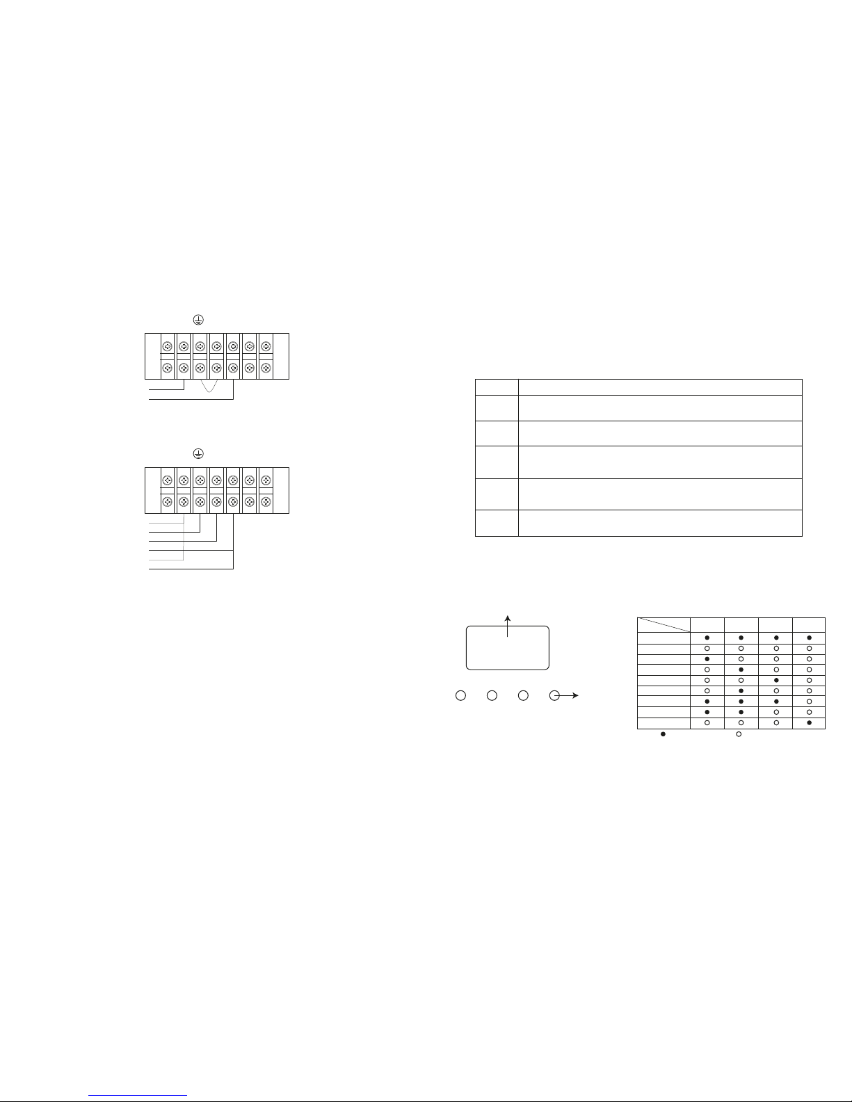
6) Then, modify charger voltage according to the table below to match the setting number on the control board. There are 5
jumpers on the charger board. Please refer to the below table to modify charger voltage.
7) After executing the previous steps, replace the UPS cover. Switch on the input breaker and the UPS will enter into the
Bypass mode. If the UPS is in maintenance Bypass mode, turn the maintenance switch to the UPS position before turning
on the system.
Note: 0 = no jumper; 1 = connect with jumper; X = the pins are for other functions.
Note: 0 = no jumper; 1 = connect with jumper.
Battery number
in series
JP1
pin1 & pin2 pin3 & pin4 pin5 & pin6 pin7 & pin8 pin9 & pin10
16
X X
1
0
0
17
X X
0
1
1
18
X X
0
1
0
19
X X
0
0
1
20
X X
0
0
0
Battery number
in series
16
17
18
19
20
Charge
voltage (V) JP01 JP02 JP03 JP04 JP05
218 0 0 0 1 0
232 0 0 1 0 0
245 0 1 0 0 0
259 1 0 0 0 0
273 0 0 0 0 0
Input and battery voltage information
Indicates the battery is not connected.
Low battery and low voltage indicator.
Indicates the input voltage or frequency, or battery voltage.
VAC: input voltage VDC: battery voltage Hz: input frequency

Note: 0 = no jumper; 1 = connect with jumper
13. Changing charging current
1) This operation should only be performed by trained and qualified technicians.
2) Turn off the UPS. If the load couldn’t be cut off, you should remove the cover of maintenance bypass switch on the rear
panel and turn the maintenance switch to the BPS position first.
3) Switch off the input breaker.
4) Remove the cabinet cover, and disconnect battery wire. Then modify the jumpers on the charger board to set the charging
current (refer to table below). Be careful that the maximum setting should not exceed the charging current acceptable for the
battery.
3.5 Parallel operation
UPS installation for parallel systems
If the UPS is only available for single operation, you may skip this section to the next.
1. Please follow the instructions to make sure the UPS systems are correctly wired for parallel operation. Refer to the
illustration below:
Charge current (A)
1A
2A
3A
4A
JP06 JP07 JP08
0 0 1
0 1 0
1 0 0
0 0 0
1. Failure to connect the Non-isolated neutral between each UPS may permanently damage the units.
2. Connect the output of each UPS to an output breaker.
3. Connect all output breakers to a main breaker. The latter is the one that will be connected to the loads.
4. If using external power banks, each UPS must be connected to its own power bank. In the event a single power bank is used
for all the UPS units, it will cause permanent damage to the equipment.
5. Connect both parallel cables between each UPS, the communications cable (DB-25) and the load balancing cable, as
illustrated below:
Once the above connections are completed, verfify that the following conditions are met:
1. Verify that the input voltage is the same for all UPS units (208, 220, 230 o 240V)
2. Turn on the UPS and the battery breaker located on the back panel of the UPS.
3. If the configuration is successful, the following screen will be displayed in all UPS units.
4. Verify the output voltage in Bypass mode using one enabled output breaker.
5. Next, turn the other output breaker on making sure that output is the same ouput in every UPS. The output difference among
all UPS units must not exceed 1V.
6. Once you have checked all the above, turn OFF all the UPS units and output breakers in order for this configuration to take
effect.
7. Finally, power on the UPS units to begin operation in Parallel mode.
3-6. Abbreviations on the LCD display
***Important*** Connect the Non-isolated neutral between each UPS. (This is the electric reference point for the transformer)
Non-isolated Neutral Output
Line 1
Output
Neutral 1
Output
Neutral 2
Input
Neutral
Output
Line 2
Input
Line
L1 N1 L2 N2 L1 L2L1 N1 L2 N2 L1 L2
3-7. UPS parameter settings
Three parameters need to be configured in order to set up the UPS. Refer to the following diagram.
List of the 15 programs for parameter 1:
ENA
DIS
ATO
BAT
Enable
Disable
Auto
Battery
Abbreviation Display content Meaning
NCF
CF
SUB
Normal mode (not CVCF mode)
CVCF mode
Subtract
Communication port connection
Parallel cable connections

1. Failure to connect the Non-isolated neutral between each UPS may permanently damage the units.
2. Connect the output of each UPS to an output breaker.
3. Connect all output breakers to a main breaker. The latter is the one that will be connected to the loads.
4. If using external power banks, each UPS must be connected to its own power bank. In the event a single power bank is used
for all the UPS units, it will cause permanent damage to the equipment.
5. Connect both parallel cables between each UPS, the communications cable (DB-25) and the load balancing cable, as
illustrated below:
Once the above connections are completed, verfify that the following conditions are met:
1. Verify that the input voltage is the same for all UPS units (208, 220, 230 o 240V)
2. Turn on the UPS and the battery breaker located on the back panel of the UPS.
3. If the configuration is successful, the following screen will be displayed in all UPS units.
4. Verify the output voltage in Bypass mode using one enabled output breaker.
5. Next, turn the other output breaker on making sure that output is the same ouput in every UPS. The output difference among
all UPS units must not exceed 1V.
6. Once you have checked all the above, turn OFF all the UPS units and output breakers in order for this configuration to take
effect.
7. Finally, power on the UPS units to begin operation in Parallel mode.
3-6. Abbreviations on the LCD display
3-7. UPS parameter settings
Three parameters need to be configured in order to set up the UPS. Refer to the following diagram.
List of the 15 programs for parameter 1:
*Y means that this program can be set in this mode
09
10
11
12
13
14
15
Y
Y
Y
Y
Y
Y
Y
Y
Y
Y
Y
Y
Y
Y
Y
Y
Y
Y
Y
Y
Y
Y
Y
Reserved for future use
01
02
03
04
05
06
07
08
Y
Y
Y
Y
Y
Y
Y
Y
Y
Y
Y
Y
Output voltage
Output frequency
Voltage range for bypass
Frequency range for bypass
ECO mode enable/disable
Voltage range for ECO mode
ECO mode frequency range setting
Bypass mode setting
Battery backup time setting
Reserved
Reserved
Hot standby function enable/disable
Battery voltage adjustment
Charger voltage adjustment
Output voltage adjustment
Code Description Bypass
Y
AC ECO CVCF Battery Battery
test
Abbreviation Display content Meaning
ADD
ON
OFF
FBD
OPN
RES
PAR
Add
On
Off
Not allowed
Allow
Reserved
Parallel
Note: All parameter settings will be saved only when UPS shuts down normally with internal or external battery connection. (Normal
UPS shutdown means turning off input breaker in bypass/no output mode).
Parameter 3: Output voltage
You may choose the following output voltage in parameter 3:
For 100/110/115/120/127VAC models, you may choose the following output
voltage:
208: The output voltage is 208VAC
220: The output voltage is 220VAC
230: The output voltage is 230VAC
240: The output voltage is 240VAC
100: The output voltage is 100VAC
110: The output voltage is 110VAC
115: The output voltage is 115VAC
120: The output voltage is 120VAC
127: The output voltage is 127VAC
Interface Setting
Parameter 2: Output frequency
To set the output frequency, choose any of the following three options in
parameter 2:
50.0Hz: The output frequency is set to 50.0Hz.
60.0Hz: The output frequency is set to 60.0Hz.
ATO: When selected, the output frequency will be set according to the latest
normal utility frequency. If it ranges from 46Hz to 54Hz, the output frequency
will be 50.0Hz.
If it ranges from 56Hz to 64Hz, the output frequency will be set at 60.0Hz.
ATO is the default setting.
Parameter 3: Frequency mode
Enables you to set the output frequency in either CVCF mode or no CVCF
mode. You may choose any of the following two options in parameter 3:
CF: Sets the UPS in the CVCF mode. If selected, the output frequency will be
fixed at 50Hz or 60Hz according to the setting in parameter 2. The input
frequency could range from 46Hz to 64Hz.
NCF: Sets the UPS to normal mode (not CVCF mode).
If selected, the output frequency will synchronize with the input frequency
within 46~54 Hz at 50Hz or within 56~64 Hz at 60Hz according to the setting
defined in parameter 2.
If 50Hz is selected in parameter 2, the UPS will transfer to battery mode
provided the input frequency does not fall within 46~54Hz range. If 60Hz is
selected in parameter 2, the UPS will transfer to battery mode provided the
input frequency does not fall within the 56~64Hz range.
*If ATO is selected in Parameter 2, Parameter 3 will show the current
frequency
Interface Setting
02: Output frequency settings
01: Output voltage settings
60 Hz, CVCF mode
50 Hz, Normal mode
ATO
Note: If the UPS is set to CVCF mode, the bypass function will be disabled automatically.
But when a single UPS without parallel function is powered on with utility power and before the UPS finishes the startup, there will
be a few seconds of voltage pulse (same as the input voltage) on the bypass output.
If you need to remove the pulse on this mode to better protect your load, you could contact the dealer for help.
This situation will not happen in UPS units working on parallel mode.
Parameter 1
Parameter 2
Parameter 3
Parameter 1: it is used for the different configuration options. There are 15
programs to set up. Refer to the table below.
Parameter 2 and parameter 3: they represent the setting options or values of
each program.

Parameter 2: Sets the acceptable low voltage for bypass operation. Setting
ranges from 110V to 209V, with a default value of 110V.
Parameter 3: Sets the acceptable high voltage for bypass operation. Setting
ranges from 231V to 276V, with a default value of 264V.
Interface Setting
03: Voltage range for bypass
Parameter 2: Sets the acceptable low frequency for bypass operation.
50Hz system: Setting ranges from 46.0Hz to 49.0Hz. 60Hz system: Setting
ranges from 56.0Hz to 59.0Hz. The default value is 46.0Hz/56.0Hz.
Parameter 3: Sets the acceptable high frequency for bypass operation.
50Hz: Setting ranges from 51.0Hz to 54.0 Hz. 60Hz: Setting ranges from
61.0Hz to 64.0Hz. The default value is 54.0Hz/64.0Hz.
Interface Setting
04: Frequency range for bypass
Parameter 3: Enables or disables the ECO feature. You may choose between
the following two options:
DIS: disables the ECO feature
ENA: enables the ECO feature
When the ECO feature is disabled, the voltage and frequency range can still
be set for this mode, however, such parameters will take effect only if the
ECO function has been enabled.
Interface Setting
05: ECO mode enable/disable
Parameter 2: Sets the low voltage point in ECO mode. This setting ranges
from 5% to 10% of the nominal voltage.
Parameter 3: Sets the high voltage point in ECO mode.
This setting ranges from 5% to 10% of the nominal voltage.
Interface Setting
06: Voltage range for ECO mode
Parameter 2: Sets low frequency point for ECO mode. 50Hz system: Ranges
from 46.0Hz to 48.0Hz.
60Hz system: Ranges from 56.0Hz to 58.0Hz. The default value is
48.0Hz/58.0Hz.
Parameter 3: Sets the high frequency point for ECO mode. 50Hz: Ranges
from 52.0Hz to 54.0 Hz.
60Hz: Ranges from 62.0Hz to 64.0Hz. The default value is 52.0Hz/62.0Hz.
Interface Setting
07: Frequency range for ECO mode
Parameter 3:
000~999: Sets the maximum backup time from 0min to 999min. UPS will shut
down to protect battery after backup time expires. The default value is
990min.
DIS: When battery discharge protection is disabled, the backup time will
depend on battery capacity. “DIS” is the default value.
Interface Setting
09: Battery backup time setting
Reserved
Interface Setting
10: Reserved
Reserved
Interface Setting
11: Reserved
Parameter 2:
OPN: Bypass allowed. When selected, the UPS will operate in Bypass mode
depending on the enable/disable bypass setting.
FBD: Bypass not allowed. When selected, the UPS will not be able to operate
in Bypass mode under any circumstances.
Parameter 3:
ENA: Bypass enabled. When selected, it means that the Bypass mode is
activated.
DIS: Bypass disabled. When selected, the automatic bypass may be used,
but manual bypass is never allowed. Manual bypass allows users to manually
operate the UPS in Bypass mode. For example, by pressing the OFF button in
AC mode, it will cause the unit to start running in Bypass mode.
Interface Setting
08: Bypass mode setting

Parameter 2:
HS.H: Enables or disables the Hot standby function. You may choose one of
the following two options in Parameter 3:
YES: Hot standby function is enabled. It means that the current UPS is set to
hot standby, and it will restart once electricity is reestablished, even without
having a battery connected.
NO: Hot standby function is disabled.
The UPS is operating in normal mode and cannot restart without battery.
Interface Setting
12: Hot standby function enable/disable
Parameter 2:
Select Add or Sub function to adjust battery voltage to its actual reading.
Parameter 3: the voltage ranges from 0V to 5.7V, the default value is 0V.
Interface Setting
13: Battery voltage adjustment
Parameter 2: You may choose Add or Sub to adjust the charger voltage
Parameter 3: The voltage ranges from 0V to 9.9V, the default value is 0V.
NOTE:
*Before making any voltage adjustment, be sure to disconnect all batteries
first to get the accurate charger voltage.
*We strongly suggest using the default value (0). Any modification should
match battery specifications.
Interface Setting
14: Charger voltage adjustment
15: Output voltage adjustment
Parameter 2: You may choose Add or Sub to adjust the output voltage.
Parameter 3: The voltage ranges from 0V to 6.4V, the default value is 0V.
Interface Setting
3-8. Operating mode/Status description
When parallel UPS systems are successfully set up, an additional screen with “PAR” in parameter 2 will be displayed and assigned
a number in parameter 3, as shown below. The master UPS will be assigned “001” as default, while the slave UPSs will be identified
as either “002” or “003”. The assigned numbers may be changed dynamically during operation.
Description
LCD display
AC mode
ECO mode
Description
LCD display
CVCF mode
Description
LCD display
Operating mode/status
When the input voltage is within an acceptable range, the UPS will provide pure and
stable AC power to the output. The UPS will also charge the battery in AC mode.
When the input voltage is within the voltage regulation range and ECO
mode is enabled, the UPS will bypass voltage to output for energy saving.
When input frequency is within 46 and 64Hz, the UPS can be set at a constant output
frequency of 50Hz or 60Hz. The UPS will still charge the battery under this mode.

Battery mode
Description
LCD display
Bypass mode
Battery test
Fault status
Description
LCD display
LCD display
LCD display
Operating mode/status
When the input voltage exceeds the acceptable range or during a power failure, the
UPS will start supplying power from the battery while the alarm will beep every 4
seconds.
When input voltage is within the acceptable range and bypass is enabled, turn off the
UPS in order to transfer the unit to Bypass mode. The alarm beeps every two minutes
in this case.
Description
When UPS is in AC mode or CVCF mode, press and hold the Test key for 0.5 second.
The UPS will beep once and start performing the “Battery test”. The line between I/P
and inverter icons blinks while the diagnostics is in progress. This operation is used to
check the battery status.
Description In the event of abnormal operation, the LCD panel will display the corresponding fault
message on the LCD panel.
3-9. Fault codes
3-10. Warning indicators
3-11. Warning codes
Warning code
01
07
08
09
0A
0B
0D
0E
Warning code
10
21
22
33
3A
3D
3E
Warning event
L1 IP fuse is blown
Line issues are different in a parallel system
Bypass issues are different in parallel system
Cover of maintenance switch is open
Bypass is unstable
Boot loader is missing
Warning event
Battery is not connected
Over charge
Low battery
Overload
Fan failure
EPO enable
Over temperature
Charger failure
Locked in bypass after an overload is
detected 3 times in 30 minutes
Fault event
Bus start failure
Bus over
Bus under
Bus unbalance
Inverter soft start failure
High inverter voltage
Low inverter voltage
Inverter output short circuited
Negative power fault
Inverter over current
Inverter waveform abnormal
Fault event
Battery SCR short circuited
Inverter relay short circuited
Charger short circuited
Parallel communication fault
Parallel output current unbalance
Over temperature
CPU communication failure
Overload
Battery turn-on failure
PFC current failure in battery mode
Bus voltage changes too fast
Fault code
01
02
03
04
11
12
13
14
1A
60
63
Fault code
21
24
2a
31
36
41
42
43
6A
6B
6C
Icon
None
None
None
None
None
None
None
None
None
None
Icon
None
None
None
None
None
None
None
None
None
None
Warning
Battery low
Overload
Battery unconnected
Over charge
EPO enable
Fan failure/Over temperature
Charger failure
I/P fuse broken
Overload 3 times in 30min
Alarm
Beeps once every second
Beeps twice every second
Beeps once every second
Icon (blinking)

5. Storage and maintenance
5-1. Storage
Charge the UPS for at least 7 hours before storing the unit. Cover the UPS, and place it upright in a cool, dry location. During
storage, recharge the battery in accordance with the following table:
5-2. Maintenance
The UPS system operates with hazardous voltages. Repairs may be carried out only by qualified maintenance personnel.
Even after the unit is disconnected from the mains, components inside the UPS system are still connected to the battery
packs which are potentially dangerous.
Before carrying out any kind of service and/or maintenance, disconnect the batteries and verify that no current is present and
no hazardous voltage exists in the terminals of high capability capacitor such as BUS-capacitors.
Servicing of batteries should be performed or supervised by personnel with knowledge of batteries and the required
precautions. Keep unauthorized personnel away from batteries.
Verify that no voltage between the battery terminals and the ground is present before maintenance or repair. In this product,
the battery circuit is not isolated from the input voltage. Hazardous voltages may occur between the battery terminals and the
ground.
A battery can present a risk of electric shock and high short circuit current. The following precaution should be observed
when working on batteries:
•Remove watches, rings or other metal objects.
•Use tools with insulated handles.
Replace batteries with the same type and number of units.
Do not attempt to dispose of batteries by burning them. This could cause battery explosion. The batteries must be properly
deposed according to local regulation.
Do not open or destroy batteries. Released electrolyte is highly poisonous and harmful to the skin and eyes.
Replace the fuse only with the same type and amperage in order to avoid fire hazards.
Do not disassemble the UPS system.
4. Troubleshooting guide
If the UPS system does not operate correctly, use the table below to troubleshoot the problem.
-25°C - 40°C
40°C - 45°C
Every 3 months
Every 2 months
1-2 hours
1-2 hours
Storage temperature Recharge frequency Runtime
Even though the mains supply is normal,
and there are no status indicators or
alarms.
The icon and the warning code blink
on the LCD display and the alarm starts
beeping once every second.
The and icons blink on the LCD
display and the alarm starts beeping once
every second.
The and icons blink on the LCD
display and the alarm beeps twice every
second.
Fault code 43 becomes illuminated along
with the icon on the LCD display,
and the alarm starts beeping continuously.
Fault code 14 becomes illuminated along
with the icon on the LCD display,
and the alarm starts beeping continuously.
Fault codes 01, 02, 03, 04, 11, 12, 13,
14,1A, 21, 24, 35, 36, 41, 42 or 43 become
illuminated on the LCD display, and the
alarm starts beeping continuously.
Battery backup time is shorter than its
nominal value.
The and icons become illuminated
on the LCD display, and the alarm starts
beeping once every second.
The AC input power is not properly
connected.
EPO function is enabled.
The external or internal battery is
incorrectly connected.
UPS is overloaded.
UPS is overloaded. Devices connected to
the UPS are fed directly by the electrical
network via the bypass.
After repetitive overloads, the UPS is
locked in the Bypass mode. Connected
devices are fed directly by the mains.
The UPS shuts down automatically upon
detecting an overload on the UPS output.
The UPS shuts down automatically upon
detecting a short circuit on the UPS
output.
A UPS internal fault has occurred. There
are two possible causes:
1. Power is continued to be supplied to
the load, but is done directly from the AC
grid via a bypass.
2. Power is no longer supplied to the load.
Batteries are not fully charged.
Defective batteries.
Fan is either locked, has stopped
working, or the UPS temperature is too
high.
Check to make sure the power cord is
firmly connected to an AC wall socket.
Set the circuit in closed position to
disable EPO function.
Check if all batteries are properly
connected.
Remove excess loads from the UPS
output.
Remove excess loads from the UPS
output.
Remove excess loads from UPS output
first. Then shut down the UPS and restart
it.
Remove excess loads from the UPS
output and restart the unit once again.
Check the output wiring and if the
connected devices are short-circuited.
Please contact the dealer or service
center.
Charge the batteries for at least 7 hours
and then check their capacity. If the
problem still persists, consult your dealer.
Contact your dealer for a replacement.
Check fans and notify dealer.
Symptom Possible cause Solution

* Derate capacity to 50% of capacity in CVCF mode and to 90% when the output voltage is adjusted to 208VAC.
** If the UPS is installed or used in a place where the altitude is above than 1000m, the output power must be derated one
percent per 100m.
*** Product specifications are subject to change without further notice.
MPN FDC106K FDC110K
General
Capacity
Topology
Input
Nominal voltage
Voltage range (low line transfer)
Voltage range (low line comeback)
Voltage range (high line transfer)
Voltage range (high line comeback)
Frequency
Power factor
Total harmonic distortion (THD)
AC plug style
Output
Nominal voltage
AC voltage regulation (battery mode)
Frequency (synchronized range)
Frequency (battery mode)
Power factor
Efficiency (AC mode)
Efficiency (battery mode)
Overload
Transfer time (line to battery)
Transfer time (inverter to bypass)
Crest ratio
Harmonic distortion
Waveform
Total outlets
Battery
Battery type and quantity
Recharge time
Charging current
Charging voltage
Communications
LCD display
Visual indicators
Audible
Communication ports
Power management software
Environment
Operating temperature
Storage temperature
Relative humidity
Operating altitude
Audible noise
Physical appearance
Product Dimensions
Product Weight
Additional information
Warranty
6000VA/6000W 10000VA/10000W
Double conversion
110-300VAC
176VAC / 140VAC / 110VAC ± 3%
(based on load percentage 100%-80% / 80%-60% / 60%-0%)
Low-line transfer voltage + 10V
300VAC ± 3%
High line transfer voltage - 10V
46-54Hz at 50Hz system / 56-64Hz at 60Hz system
≥0.99 at 100% load
<4% at100% load / <6% at 50% load
Hard wired
104/110/115/120VAC or 208/220/230/240VAC
± 1%
46-54Hz at 50Hz system / 56-64Hz at 60Hz system
50Hz ± 0.1Hz or 60Hz ± 0.1Hz
1
> 90%
> 88%
AC mode: 100%-110%: 10min / 110%-130%: 1min / >130%: 1sec
Battery mode: 100%-110%: 30sec / 110%-130%: 10sec / >130%: 1sec
0ms
0ms
3:1 (max)
≤2% THD (linear load) / ≤6% THD (non-linear load)
Pure sine wave
Terminal block
12V / 9Ah (20)
9 hours to 90% capacity
1A ± 10% (max)
273VDC ± 1%
Graphical LCD with blue backlight
Status LEDs
Battery mode: Sounds every 4 seconds
Low battery: Sounds every second
Overload: Sounds every 0.5 second
Fault: Continuous sound
SNMP, RS-232, USB
Included
32°F-104°F
UPS: -5°F-140°F Battery: 32°F-95°F
20-90% non-condensing
<1000m
Every 100m above 1000m decreases output power 1% up to 4000m
<58dB at 1 meter
23.3x9.9x32.5in
256lb 313lb
Two years *
6. Technical specifications

www.forzaups.com
This manual suits for next models
1
Table of contents
Other Forza UPS manuals

Forza
Forza FIO-P11K12 User manual

Forza
Forza FDC-1001RUL User manual

Forza
Forza FDC-1002T-C User manual

Forza
Forza FDC-1002T User manual

Forza
Forza FX-1500LCD User manual

Forza
Forza Atlas 2-3KVA User manual

Forza
Forza SL402UL User manual

Forza
Forza HT-752LCD-C User manual

Forza
Forza FDC-003K User manual

Forza
Forza DC-140USB User manual

Forza
Forza SL-1501UL User manual

Forza
Forza XG-1201LCD User manual

Forza
Forza Elipse Series User manual

Forza
Forza FDC-106KMR-ISO User manual

Forza
Forza FDC-1502R User manual

Forza
Forza FDC-2012R-I User manual

Forza
Forza SL-802UL-A User manual

Forza
Forza HT-750LCD User manual

Forza
Forza HT-650LCD User manual

Forza
Forza FDC-1002T-A User manual