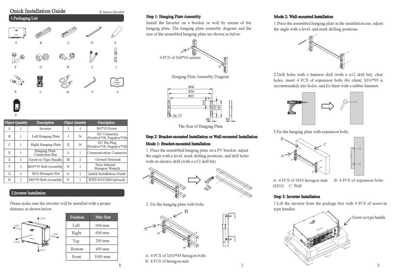
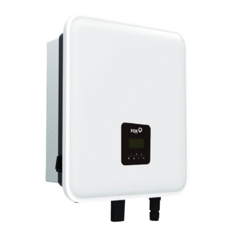
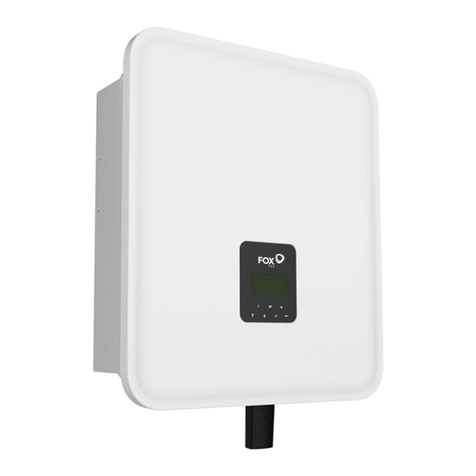
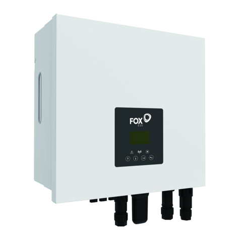
FoxESS US Series User manual

US SERIES
User Manual
FOXESS CO., LTD.

1
Table of Contents
1. Notes on This Manual ............................................................................................................................ 3
1.1 Scope of Validity .......................................................................................................................... 3
1.2 Target Group ................................................................................................................................3
1.3 Symbols Used ..............................................................................................................................3
2. Safety Precautions ................................................................................................................................. 5
2.1 Appropriate Usage .......................................................................................................................5
2.2 PE Connection and Leakage Current .......................................................................................... 5
3. Introduction ............................................................................................................................................ 7
3.1 Basic Features .............................................................................................................................7
3.2 Dimensions .................................................................................................................................. 8
3.3 Terminals of Hybrid Inverter .........................................................................................................9
4. Technical Data ......................................................................................................................................10
4.1 PV Input (For Hybrid Only) ........................................................................................................ 10
4.2 Battery ....................................................................................................................................... 10
4.3 AC Output/Input ......................................................................................................................... 11
4.4 Efficiency, Protection and Standard ...........................................................................................13
4.5 General Data ............................................................................................................................. 14
5. Installation ............................................................................................................................................16
5.1 Check for Physical Damage ...................................................................................................... 16
5.2 Packing List ............................................................................................................................... 16
5.3 Mounting ....................................................................................................................................16
6. Electrical Connection ........................................................................................................................... 23
6.1 Battery Connection .................................................................................................................... 23
6.2 PV Connection (For Hybrid Only) .............................................................................................. 24
6.3 Grid Connection .........................................................................................................................25
6.4 Communication Device Installation (Optional) ...........................................................................27
6.5 E-STOP Wiring .......................................................................................................................... 28
6.6 FOX Hub Wiring .........................................................................................................................29
6.7 System Wiring Diagram ............................................................................................................. 31
6.8 Hybrid Inverter Start-Up .............................................................................................................33
6.9 Hybrid Inverter Switch Off ..........................................................................................................33
7. Operations on the FoxEssUS App ....................................................................................................... 34
7.1 App Overview .............................................................................................................................34
7.2 Downloading and Installing the App .......................................................................................... 34
7.3 Registering the App ................................................................................................................... 34
7.4 Resetting the Password .............................................................................................................36
7.5 WIFI Configuration .....................................................................................................................36
7.6 App Operations by the Installer ..................................................................................................38
7.7 App Operations by the End User ............................................................................................... 46
8. Operation ............................................................................................................................................. 55
8.1 Control Panel ............................................................................................................................. 55
9. Maintenance .........................................................................................................................................56
9.1 Alarm List ...................................................................................................................................56

2
9.2 Troubleshooting and Routine Maintenance ............................................................................... 67
10. Decommissioning ...............................................................................................................................69
10.1 Dismantling the hybrid inverter ................................................................................................ 69
10.2 Packaging ................................................................................................................................ 69
10.3 Storage and Transportation ..................................................................................................... 69

3
1. Notes on This Manual
1.1 Scope of Validity
This manual describes the assembly, installation, commissioning, maintenance and troubleshooting of
the following model(s) of FOXESS products:
H1-3.8-US H1-5.7-US H1-7.6-US H1-9.6-US H1-11.4-US
AC1-3.8-US AC1-5.7-US AC1-7.6-US AC1-9.6-US AC1-11.4-US
Note: Please keep this manual where it will be accessible at all times.
1.2 Target Group
This manual is for qualified electricians. The tasks described in this manual only can be performed by
qualified electricians.
1.3 Symbols Used
The following types of safety instructions and general information appear in this document as described
below:
Danger!
“Danger” indicates a hazardous situation which, if not avoided, will result in death or
serious injury.
Warning!
“Warning” indicates a hazardous situation which, if not avoided, could result in
death or serious injury.
Caution!
“Caution” indicates a hazardous situation which, if not avoided, could result in minor
or moderate injury.
Note!
“Note” provides important tips and guidance.
Table 1-1 Label Description
This section explains the symbols shown on the inverter and on the type label:
Symbols
Explanation
Certified to meet the requirements of CSA-C22.2 No. 107.1-16, UL Std.
No. 1741-Third Edition, UL 1741 SB, IEEE 1547-2018, IEEE
1547.1-2020, and CA Rule 21.
Beware of burning.
The case temperature may exceed 140°F (60℃) during operation. Avoid
contact during operation.
Danger of high voltages.
Disconnect from the grid and the PV generator before opening the device.

4
Table 1-2 Label Description
Danger.
Risk of electric shock!
Danger to life due to high voltage.
There is residual voltage in the inverter which needs 5 min to discharge.
Wait 5 min before you open the upper cover or the lower cover.
Read the manual.
Product should not be disposed as household waste.

5
2. Safety Precautions
2.1 Appropriate Usage
US series hybrid inverters are designed and tested in accordance with international safety requirements.
However, certain safety precautions must be taken when installing and operating this hybrid inverter. The
installer must read and follow all instructions, cautions and warnings in this installation manual.
-All operations including transport, installation, start-up and maintenance, must be carried out by
qualified, trained personnel.
-The electrical installation & maintenance of the hybrid inverter shall be conducted by a licensed
electrician and shall comply with local wiring rules and regulations.
-Before installation, check the unit to ensure it is free of any transport or handling damage, which
could affect insulation integrity or safety clearances. Choose the installation location carefully
and adhere to specified cooling requirements. Unauthorized removal of necessary protections,
improper use, incorrect installation and operation may lead to serious safety and shock hazards
or equipment damage.
-Before connecting the inverter to the power distribution grid, contact the local power distribution
grid company to get appropriate approvals. This connection must be made only by qualified
technical personnel.
-Do not install the equipment in adverse environmental conditions such as in close proximity to
flammable or explosive substances; in a corrosive or desert environment; where there is
exposure to extreme high or low temperatures; or where humidity is high.
-Do not use the equipment when the safety devices do not work or are disabled.
-Use personal protective equipment, including gloves and eye protection during the installation.
-Inform the manufacturer about non-standard installation conditions.
-Do not use the equipment if any operating anomalies are found. Avoid temporary repairs.
-All repairs should be carried out using only approved spare parts, which must be installed in
accordance with their intended use and by a licensed contractor or authorized FOXESS service
representative.
-Liabilities arising from commercial components are delegated to their respective manufacturers.
-Any time the hybrid inverter has been disconnected from the public network, please be
extremely cautious as some components can retain charge sufficient to create a shock hazard.
Prior to touching any part of the hybrid inverter please ensure surfaces and equipment are
under touch safe temperatures and voltage potentials before proceeding.
2.2 PE Connection and Leakage Current
PV System Residual Current Factors
-In every PV installation, several elements contribute to the current leakage to protective earth
(PE). These elements can be divided into two main types.
-Capacitive discharge current-Discharge current is generated mainly by the parasitic
capacitance of the PV modules to PE. The module type, the environmental conditions (rain,
humidity) and even the distance of the modules from the roof can effect the discharge current.
Other factors that may contribute to the parasitic capacitance are the inverter’s internal
capacitance to PE and external protection elements such as lighting protection.
-During operation, the DC bus is connected to the alternating current grid via the inverter. Thus, a
portion of the alternating voltage amplitude arrives at the DC bus. The fluctuating voltage

6
constantly changes the charge state of the parasitic PV capacitor (i.e. capacitance to PE). This
is associated with a displacement current, which is proportional to the capacitance and the
applied voltage amplitude.
-Residual current-if there is a fault, such as defective insulation, where an energized cable
comes into contact with a grounded person, an additional current flows, known as a residual
current.
Residual Current Device (RCD)
-All FOXESS hybrid inverters incorporate a certified internal RCD (Residual Current Device) to
protect against possible electrocution in case of a malfunction of the PV array, cables or inverter
(DC). The RCD in the FOXESS inverter can detect leakage on the DC side. There are 2 trip
thresholds for the RCD as required by the UL1741 standard. A low threshold is used to protect
against rapid changes in leakage typical of direct contact by people. A higher threshold is used
for slowly rising leakage currents, to limit the current in grounding conductors for the safety. The
default value for higher speed personal protection is 30mA, and 30mA, 60mA, 150mA per unit
for lower speed fire safety.

7
3. Introduction
3.1 Basic Features
US series is high-quality hybrid inverters which can convert solar energy to AC energy and store energy
into battery. The hybrid inverter can be used to optimize self-consumption, store in the battery for future
use or feed-in to public grid. Work mode depends on PV energy and user’s preference.
• System advantages:
-Easy installation: flexible configuration, plug and play set-up
-High Voltage:compatible with high-voltage batteries for maximum round-trip efficiency.
-Type 4X: engineered to last with maximum flexibility, and suitable for outdoor installation.
-Remote monitoring:monitor your system remotely via smartphone app or web portal.
-100% imbalance for Split-Phase Loads.
-High backup power, up to 12.5kW.
-High scalability, up to 4 inverters in parallel.
-Fast battery charging, up to 50A changing and 60A discharging current.
-RSD transmitter inside: a Tigo or APsystem transmitter is integrated in the inverter ,and
only RSD receivers should be installed by the installer.
-RGM inside:a 0.5% accuracy revenue grade meter (RGM) is integrated in the inverter and FOX
Hub to finance the solar array.
-UPS switchover time: the switchover time from on-grid to off-grid or from off-grid to on-grid is
less than 15ms.
-Generator ready: the FOX Hub is ready to connect to an up to 200A generator.
-Smart loads: 240V or 120V loads can be connected to the FOX Hub and controlled according
to the time and SOC.
-Safety&Reliability: transformerless design with software and hardware protection.
-Arc detection function: capability of detecting up to 35A arc current. When the PV panel
produces arc, the inverter will shut down immediately, disconnect the grid side relay, BDC relay
will send shutdown instructions to the battery to disconnect the battery. Meanwhile, turn off the
quick shut-off device (RSD) to avoid the fire of the PV panel. After the arcing occurs, the inverter
will report the arcing fault immediately and upload it to the cloud.
• Work modes:
Work modes
Description
Self-use
(with PV Power)
Priority: load>battery>grid
The energy produced by the PV system is used to optimize self-consumption.
The excess energy is used to charge the batteries, and then exported to gird.
Self-use
(without PV Power)
When no PV supplied, battery will discharge for local loads firstly, and grid will
supply power when the battery capacity is not enough.
Time-of-use
Priority: battery>load>grid (when charging)
Priority: load>battery>grid (when discharging)
This mode applies the area that has electricity price between peak and valley.
User can use off-peak electricity to charge the battery.
The charging and discharging time can be set flexibly, and it also allows to
choose whether charge from the grid or not.

8
Back up mode
When the grid is off, system will supply emergency power from PV or battery to
the home loads (Battery is necessary in off-grid mode).
Load shifting mode
This is the preferred mode under a time-of-use rate schedule in which mode the
user can set the On peak, Off peak, and Mid peak hours.
Load Shifting provides users with two options: solar power to storage first, and
solar power to family loads first.
Table 3-1 Work Mode Description
Note: Charging time is when the battery is charged within the set time range. The setting of time can be
used in the above three modes.
3.2 Dimensions
Figure 3-1 Enclosure Dimensions

9
3.3 Terminals of Hybrid Inverter
Figure 3-2 Bottom of Hybrid Inverter
Item
Description
A
BAT
B
PV (For Hybrid Only)
C
WIFI/GPRS/4G/USB
D
AC-GRID
E
AC-BACKUP
F
DC Switch (For Hybrid Only)
G
Waterproof Lock Valve
H
Waterproof Lock Valve
I
COM1
J
COM2
Table 3-2 Terminal Description

10
4. Technical Data
4.1 PV Input (For Hybrid Only)
Module
H1-3.8-US
H1-5.7-US
H1-7.6-US
H1-9.6-US
H1-11.4-US
PV INPUT
Max. PV input power (W)
5700
8550
11400
14400
17100
Nominal DC voltage (V)
380
Max. DC voltage (V)
600
System startup voltage (V)
100
MPPT Voltage Range (V)
80-550V
MPPT Voltage Range (V) (Full
Load)
204–500
204–500
271–500
257–500
305–500
Max. PV input current per MPPT (A)
28/14
28/14/14
Max. input short circuit current per
MPPT (A)
44/22
44/22/22
No. of MPPT
2
3
Strings per MPPT
2/1
2/1/1
4.2 Battery
Module
H1-3.8-US
H1-5.7-US
H1-7.6-US
H1-9.6-US
H1-11.4-US
Battery
Battery type
Li-ion
Nominal battery voltage (V)
360
DC operating voltage range
85-460

11
Module
H1-3.8-US
H1-5.7-US
H1-7.6-US
H1-9.6-US
H1-11.4-US
(V)
Full Load DC operating
voltage range (V)
95-460
140-460
190-460
235-460
280-460
Max. continuous charge and
discharge current (A)
50
Max. continuous
charge/discharge power (W)
5700/4180
8550/6270
11400/8360
14400/10560
17100/12540
Peak discharge current for 60
sec. (A)
60
BMS Communication
interface
CAN2.0
Module
AC1-3.8-US
AC1-5.7-US
AC1-7.6-US
AC1-9.6-US
AC1-11.4-US
Battery
Battery type
Li-ion
Nominal battery
voltage (V)
360
DC operating voltage
range (V)
85-460
Full load DC operating
voltage range (V)
95-460
140-460
190-460
235-460
280-460
Max. continuous
charge and discharge
current (A)
50
Max. continuous
charge/discharge
power (W)
3800/4180
5700/6270
7600/8360
9600/10560
11400/12540
Peak discharge current
for 60 sec. (A)
60
BMS Communication
interface
CAN2.0
4.3 AC Output/Input
Module
H1-3.8-US
H1-5.7-US
H1-7.6-US
H1-9.6-US
H1-11.4-US
OUTPUT AC (Grid side)
nominal AC Power (W)
3800
5700
7600
9600
11400
Max. AC Apparent Power (VA)
3800
5700
7600
9600
11400
Nominal AC output voltage (V)
240
AC Voltage Range (V)
211~264
Nominal AC output current (A)
15.8
23.8
31.7
40.0
47.5
Max.AC output current (A)
15.8
23.8
31.7
40.0
47.5
Nominal AC output frequency
(Hz)
60

12
Module
H1-3.8-US
H1-5.7-US
H1-7.6-US
H1-9.6-US
H1-11.4-US
Operating AC frequency range
(Hz)
57~63
Output power factor
>0.99 (0.8 leading - 0.8 lagging)
Total harmonic distortion
<3%
INPUT AC (Grid side)
Max.AC input power (W)
3800
5700
7600
9600
11400
Input voltage range (V)
211~264
Nominal AC input frequency
(Hz)
60
Max.AC input current (A)
15.8
23.8
31.7
40.0
47.5
OUTPUT AC (Back-up)
Rated output power (W)
3800
5700
7600
9600
11400
Max. apparent output power
(VA)
4180
6270
8360
10560
12540
Peak output power for 60 sec.
(W)
5130
7695
10260
12960
15390
Peak output power for 10 min.
(W)
4560
6840
9120
11520
13680
Nominal AC output voltage
120V/240 V
Max. Continuous AC output
current (A)
17.4
26.1
34.8
44.0
52.3
Nominal AC output frequency
(Hz)
60
Imbalance for Split-Phase
Loads
100%
Maximum Output Overcurrent
Protection
25
35
45
60
70
Module
AC1-3.8-US
AC1-5.7-US
AC1-7.6-US
AC1-9.6-US
AC1-11.4-US
OUTPUT AC (Grid side)
Nominal AC Power (W)
3800
5700
7600
9600
11400
Max. AC Apparent Power
(VA)
3800
5700
7600
9600
11400
Nominal AC output voltage
(V)
240
AC Voltage Range (V)
211~264
Nominal AC output current
(A)
15.8
23.8
31.7
40.0
47.5
Max.AC output current (A)
15.8
23.8
31.7
40.0
47.5
Nominal AC output
frequency (Hz)
60
Operating AC frequency
57~63

13
range (Hz)
Output power factor
>0.99 (0.8 leading - 0.8 lagging)
Total harmonic distortion
<3%
Maximum Output
Overcurrent Protection
20
30
40
50
60
INPUT AC (Grid side)
Max.AC input power (W)
3800
5700
7600
9600
11400
Input voltage range (V)
211~264
Nominal AC input
frequency (Hz)
60
Max.AC input current (A)
15.8
23.8
31.7
40.0
47.5
OUTPUT AC (Back-up)
Rated output power(W)
3800
5700
7600
9600
11400
Max. apparent output
power (VA)
4180
6270
8360
10560
12540
Peak output power for 60
sec. (W)
5130
7695
10260
12960
15390
Peak output power for 10
min. (W)
4560
6840
9120
11520
13680
Nominal AC output voltage
120V/240 V
Max. Continuous AC
output current (A)
17.4
26.1
34.8
44.0
52.3
Norminal AC output
frequency (Hz)
60
Imbalance for Split-Phase
Loads
100%
4.4 Efficiency, Protection and Standard
Module
H1-3.8-US
H1-5.7-US
H1-7.6-US
H1-9.6-US
H1-11.4-US
EFFICIENCY
Max. efficiency
97.6%
PROTECTION
DC Reverse-polarity Protection
YES
DC Switch
YES
DC Surge Protection
Type II
Insulation Resistance
Monitoring
YES
AC Surge Protection
Type II
AC short-circuit Protection
YES
Ground Fault Monitoring
YES
Grid Monitoring
YES
Anti-islanding Protection
YES
Residual-current Monitoring
YES

14
Module
H1-3.8-US
H1-5.7-US
H1-7.6-US
H1-9.6-US
H1-11.4-US
Unit
AFCI Protection
YES
STANDARD
Safety and EMC
UL Std No. 1741, UL62109, IEEE1547-2018, IEEE1547a-2020,
IEEE1547.1-2020; CSA C22.2 No.107.1-16, UL1998, UL1699B, FCC
part15 CLASS B, HECO
4.5 General Data
Module
H1-3.8-US
H1-5.7-US
H1-7.6-US
H1-9.6-US
H1-11.4-US
Dimension and Weight
Dimension (W/H/D)
462/658/234.5mm
Weight
83.8 lbs/38kg
Enclosure rating
Type 4X
Operation temperature
range
–13°F~+140°F (–25 °C ~ +60 °C) derating above 104°F(40℃)
Relative humidity
0-100% (No Condensation)
Typical noise emission
<35dB
Max. operation altitude
9843 ft(3000 m) (>6, 560 ft (2000 m) derating)
Internal Consumption at
Night
<25W
Topology
Transformerless
Cooling Method
Natural convection
HMI
Module
AC1-3.8-US
AC1-5.7-US
AC1-7.6-US
AC1-9.6-US
AC1-11.4-US
EFFICIENCY
Max. efficiency
97.60%
Round-trip efficiency
90.90%
PROTECTION
DC Surge Protection
Type II
Insulation Resistance
Monitoring
YES
AC Surge Protection
Type II
AC short-circuit Protection
YES
Ground Fault Monitoring
YES
Grid Monitoring
YES
Anti-islanding Protection
YES
Residual-current Monitoring
Unit
YES
STANDARD
Safety and EMC
UL 1741, IEEE1547-2018, IEEE1547a-2020, IEEE1547.1-2020; CSA
C22.2 No.107.1-16, UL1998,UL1699B, FCC part15 CLASS B, HECO

15
Module
H1-3.8-US
H1-5.7-US
H1-7.6-US
H1-9.6-US
H1-11.4-US
Display
LED, App, Website
Communication interface
CAN2.0, RS485, Meter, CT, ISO alarm, SUNSPEC
Monitoring Module: Smart
WiLAN/GPRS
Optional
Warranty
Standard 10 years
Module
AC1-3.8-US
AC1-5.7-US
AC1-7.6-US
AC1-9.6-US
AC1-11.4-US
Dimension and Weight
Dimension (W/H/D)
658/462/234.5mm
Weight
80.5 lbs /36.5kg
Enclosure rating
Type 4X
Operation temperature
range
–13°F~+140°F (–25 °C ~ +60 °C) derating above 104°F(40℃)
Relative humidity
0-100% (No Condensation)
Typical noise emission
<35dB
Max. operation altitude
9843 ft(3000 m) ( >6, 560 ft (2000 m) derating)
Internal Consumption at
Night
<25W
Topology
Transformerless
Cooling Method
Natural convection
HMI
Display
LED, App, Website
Communication interface
CAN2.0, RS485, Meter, CT, ISO alarm, SUNSPEC
Monitoring Module:
Smart WiLAN/GPRS
Optional
Warranty
Standard 10 years

16
5. Installation
5.1 Check for Physical Damage
Make sure the hybrid inverter is intact during transportation. If there is any visible damage, such as
cracks, please contact your dealer immediately.
5.2 Packing List
Open the package and take out the product, please check the accessories first. The packing list is shown
as below.
Figure 5-1 Packing List
Object
Quantity
Description
Object
Quantity
Description
A
1
Inverter
F
1
Quick Installation Guide
B
1
Bracket
G
1
WiLAN/GPRS (Optional)
C
4
Expansion tube
H
1
E-STOP
D
4
Expansion screw
I
1
FOX Hub
E
1
Set screw
Table 5-1 Object Description
5.3 Mounting
•Installation Precaution
Make sure the installation site meets the following conditions:
-Not in direct sunlight.
-Not in areas where highly flammable materials are stored.
-Not in potential explosive areas.
-Not in the cool air directly.
-Not near the television antenna or antenna cable.
-Not higher than altitude of about 3000m above sea level.
-Not in environment of precipitation or humidity (>100%).
-Under good ventilation condition.
-The ambient temperature in the range of -25°C to +60°C.
-The slope of the wall should be within ±5°.

17
-The wall hanging the hybrid inverter should meet conditions below:
1. Solid brick/concrete, or strength equivalent mounting surface;
2. Hybrid inverter must be supported or strengthened if the wall's strength isn't enough (such as
wooden wall, the wall covered by thick layer of decoration).
-Please avoid direct sunlight, rain exposure, snow laying up during installation and operation.
•Space Requirement
-Reserve enough clearance around the inverter to ensure sufficient space for installation and
heat dissipation.
Figure 5-2 Installation space requirements Table 5-2 Minimum size for installation
-When installing multiple hybrid inverters, install them in a staggered arrangement.

18
Figure 5-3 Staggered installation
•Mounting Steps
Tools required for installation:
Category
Tools
Installation
Sleeves
Crimping pliers
Cross screwdriver
Stripping pliers
Percussion drill
Internal hexagonal wrench

19
•Inverter Installation
Step 1: Fix the bracket on the wall
Choose the place on which you want to install the hybrid inverter. Place the bracket on the wall and mark
the position of the 4 holes from bracket.
Figure 5-4 Marking the position of the bracket
Drill holes with electric drill, make sure the holes are at least 50mm deep, and then tighten the expansion
tubes.
Figure 5-5 Tightening expansion tubes
Insert the expansion tubes into the holes and tighten them. Install the bracket with the expansion screws.
Figure 5-6 Installing the bracket
Step 2: Match the hybrid inverter with wall bracket
Crystal head crimping pliers
Straight screwdriver
This manual suits for next models
10
Table of contents
Other FoxESS Inverter manuals

FoxESS
FoxESS LV5200 User manual

FoxESS
FoxESS E Series User manual

FoxESS
FoxESS S700-G2 User manual

FoxESS
FoxESS KH Series User manual

FoxESS
FoxESS T Series User manual

FoxESS
FoxESS T Series User manual

FoxESS
FoxESS H3 Series User manual

FoxESS
FoxESS R Series User manual

FoxESS
FoxESS H1 Series User manual

FoxESS
FoxESS S Series User manual
Popular Inverter manuals by other brands

Zipper Mowers
Zipper Mowers ZI-STE2800IV user manual

Generac Power Systems
Generac Power Systems 004810-0 owner's manual

ABB
ABB PVI-5000-TL-OUTD-US Quick installation guide

C.E. Nierhoff & Co
C.E. Nierhoff & Co C524 troubleshooting guide

Daikin
Daikin FLXS-BAVMB Service manual

Stephill
Stephill SSDP30 Handbook