FoxESS S Series User manual


S Series User Manual www.fox-ess.com P a g e | 1
Table of Contents
1. Important Notes........................................................................................................................................................ 2
1.1 Scope................................................................................................................................................................... 2
1.2 Target Group .................................................................................................................................................... 2
1.3 Symbols Used................................................................................................................................................... 2
1.4 Symbols Explanation...................................................................................................................................... 2
2. Safety ............................................................................................................................................................................ 3
2.1 Appropriate Usage ......................................................................................................................................... 3
2.2 PE Connection and Leakage Current ....................................................................................................... 4
2.3 Surge protection devices (SPDs) for PV installation............................................................................ 4
3. About Product ........................................................................................................................................................... 5
3.1 About S Series Inverter.................................................................................................................................. 5
3.2 Basic Features................................................................................................................................................... 5
3.3 Terminals Introduction .................................................................................................................................. 6
3.4 Dimensions........................................................................................................................................................ 6
4. Technical Data ........................................................................................................................................................... 7
4.1 DC Input............................................................................................................................................................. 7
4.2 AC Output ......................................................................................................................................................... 7
4.3 Efficiency, Safety and Protection................................................................................................................ 7
4.4 General Data..................................................................................................................................................... 8
5. Installation................................................................................................................................................................... 8
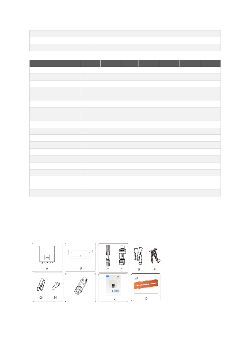
5.1 Packing List........................................................................................................................................................ 8
5.2 Preparation........................................................................................................................................................ 9
5.3 Installation Space Required ......................................................................................................................... 9
5.4Tools Required...............................................................................................................................................10
5.5 Installation Steps ...........................................................................................................................................10
5.6 Wiring Steps.................................................................................................................................................... 11
5.7 Earth Connection...........................................................................................................................................14
5.8 Communication Device Installation (Optional) ...................................................................................14
5.9 Inverter Start-Up...........................................................................................................................................16
5.10 Inverter Switch Off........................................................................................................................................17
6. Operation ..................................................................................................................................................................18
6.1 Control Panel..................................................................................................................................................18
6.2 Function Tree..................................................................................................................................................19
7. Maintenance............................................................................................................................................................. 19
7.1 Alarm List .........................................................................................................................................................19
7.2 Troubleshooting............................................................................................................................................21
7.3 Routine maintenance................................................................................................................................... 21
8. Decommissioning...................................................................................................................................................22
8.1 Dismantling the Inverter............................................................................................................................. 22
8.2 Packaging ........................................................................................................................................................22
8.3 Storage and Transportation ......................................................................................................................22

S Series User Manual www.fox-ess.com P a g e | 2
1. Important Notes
1.1 Scope
This manual describes the assembly, installation, commissioning, maintenance and troubleshooting of the
following model(s) of FoxESS products:
S Series:
S700 S1000 S1500 S2000
S2500 S3000 S3300*
Note: Please keep this manual where it will be accessible at all times.
*The S3300 model is for the Indian and Polish markets only.
1.2 Target Group
This manual is for qualified personnel only. The tasks described in this manual will need to be performed by
professional, suitably qualified technicians only.
1.3 Symbols Used
The following types of safety instructions and general information appear in this document as described below:
Danger!
“Danger” indicates a hazardous situation which, if not avoided, will result in death or
serious injury.
Warning!
“Warning” indicates a hazardous situation which, if not avoided, could result in death or
serious injury.
Caution!
“Caution” indicates a hazardous situation which, if not avoided, could result in minor or
moderate injury.
Note!
“Note” provides important tips and guidance.
1.4 Symbols Explanation
This section explains the symbols shown on the inverter and on the type label:
Symbols
Explanation
Symbol Explanation CE mark. The inverter complies with the requirements of the applicable CE
guidelines.
Beware of hot surface. The inverter can become hot during operation. Avoid contact during
operation.
Danger of high voltages.
Danger to life due to high voltages in the inverter!

S Series User Manual www.fox-ess.com P a g e | 3
Danger.
Risk of electric shock!
Danger to life due to high voltage.
There is residual voltage in the inverter which needs 5 min to discharge.
Wait 5 min before you open the upper lid or the DC lid.
Read the manual
Product should not be disposed as household waste
2. Safety
2.1 Appropriate Usage
The S Series inverter is designed and tested in accordance with international safety requirements. However,
certain safety precautions must be taken when installing and operating this inverter. The installer must read and
follow all instructions, cautions and warnings in this installation manual.
▪All operations including transport, installation, start-up and maintenance, must be carried out by qualified,
trained personnel.
▪The electrical installation & maintenance of the inverter shall be conducted by a licensed electrician and
shall comply with local wiring rules and regulations.
▪Before installation, check the unit to ensure it is free of any transport or handling damage, which could
affect insulation integrity or safety clearances. Choose the installation location carefully and adhere to
specified cooling requirements. Unauthorized removal of necessary protections, improper use, incorrect
installation and operation may lead to serious safety and shock hazards or equipment damage.
▪Before connecting the inverter to the power distribution grid, contact the local power distribution grid
company to get appropriate approvals. This connection must be made only by qualified technical
personnel.
▪Do not install the equipment in adverse environmental conditions such as in close proximity to flammable
or explosive substances; in a corrosive environment; where there is exposure to extreme high or low
temperatures; or where humidity is high.
▪Do not use the equipment when the safety devices do not work or are disabled.
▪Use personal protective equipment, including gloves and eye protection during the installation.
▪Inform the manufacturer about non-standard installation conditions.
▪Do not use the equipment if any operating anomalies are found. Avoid temporary repairs.
▪All repairs should be carried out using only approved spare parts, which must be installed in accordance
with their intended use and by a licensed contractor or authorized Fox-ESS service representative.
▪Liabilities arising from commercial components are delegated to their respective manufacturers.
▪Any time the inverter has been disconnected from the public network, please be extremely cautious as
some components can retain charge sufficient to create a shock hazard. Prior to touching any part of the
inverter please ensure surfaces and equipment are under touch safe temperatures and voltage potentials
before proceeding.

S Series User Manual www.fox-ess.com P a g e | 4
2.2 PE Connection and Leakage Current
-The end-use application shall monitor the protective conductor by residual current operated protective
device (RCD) with rated fault current Ifn≤280mA which automatically disconnects the device in case of a
fault.
-DC differential currents are created (caused by insulation resistance and through capacities of the PV
generator). In order to prevent unwanted triggering during operation, the rated residual current of the RCD
has to be min 240mA. The device is intended to connect to a PV generator with a capacitance limit of
approx. 700nf.
WARNING!
High leakage current! Earth connection essential before connecting supply.
-Incorrect grounding can cause physical injury, death or equipment malfunction and increase
electromagnetic interference.
-Make sure that grounding conductor is adequately sized as required by safety regulations.
-Do not connect the ground terminals of the unit in series in case of a multiple installation. This product can
cause current with a DC component, Where a residual current operated protective device (RCD) or
monitoring device (RCM) is used for protection in case of direct or indirect contact, only an RCD or RCM of
type B is allowed on the supply side of this product.
For UK
-The installation that connects the equipment to the supply terminals shall comply with the requirements of
BS 7671.
-Electrical installation of PV system shall comply with requirements of BS 7671 and IEC 60634-7-712.
-No protection settings can be altered.
-User shall ensure that the equipment is so installed, designed and operated to maintain at all times
compliance with requirements of ESQCR22(1)(a).
For AU
Electrical installation and maintenance shall be conducted by licensed electrician and shall comply with Australia
National Wiring Rules.
2.3 Surge protection devices (SPDs) for PV installation
WARNING!
Over-voltage protection with surge arresters should be provided when the PV power system is
installed. The grid connected inverter is not fitted with SPDs in both PV input side and mains
side.
Lightning will cause damage either from a direct strike or from surges due to a nearby strike.
Induced surges are the most likely cause of lightning damage in majority or installations, especially in rural areas
where electricity is usually provided by long overhead lines. Surges may impact on both the PV array conduction
and the AC cables leading to the building. Specialists in lightning protection should be consulted during the end

S Series User Manual www.fox-ess.com P a g e | 5
use application. Using appropriate external lightning protection, the effect of a direct lightning strike into a
building can be mitigated in a controlled way, and the lightning current can be discharged into the ground.
Installation of SPDs to protect the inverter against mechanical damage and excessive stress include a surge
arrester in case of a building with external lightning protection system (LPS) when separation distance is kept. To
protect the DC system, surge suppression device (SPD type2) should be fitted at the inverter end of the DC
cabling and at the array located between the inverter and the PV generator, if the voltage protection level (VP) of
the surge arresters is greater than 1100V, an additional SPD type 3 is required for surge protection for electrical
devices.
To protect the AC system, surge suppression devices (SPD type2) should be fitted at the main incoming point of
AC supply (at the consumer’s cutout), located between the inverter and the meter/distribution system; SPD (test
impulse D1) for signal line according to EN 61632-1. All DC cables should be installed to provide as short a run
as possible, and positive and negative cables of the string or main DC supply should be bundled together.
Avoiding the creation of loops in the system. This requirement for short runs and bundling includes any
associated earth bundling conductors. Spark gap devices are not suitable to be used in DC circuits once
conducting; they won’t stop conducting until the voltage across their terminals is typically below 30 volts.
3. About Product
3.1 About S Series Inverter
S series inverters cover 0.7kW systems up to 3.3kW and are integrated with 1 MPP tracker with high efficiency
and reliability.
3.2 Basic Features
▪Advanced DSP control technology;
▪Utilizes the latest high-efficiency power component;
▪Optimal MPPT technology:
▪Wide MPPT input range.
▪Advanced anti-islanding solutions.
▪IP65 protection level.
▪Max. Efficiency up to 97.4%. EU efficiency up to 96.8%. THD<3%.
▪Safety & Reliability: transformerless design with software and hardware protection.
▪Export limitation (CT/Meter/DRM0/ESTOP).
▪Power factor regulation. Friendly HMI.
▪LED status indications.
▪LCD display technical data, human-machine interaction through touch key.
▪PC remote control.

S Series User Manual www.fox-ess.com P a g e | 6
3.3 Terminals Introduction
Item
Description
A
PV
B
DC Switch (Optional)
C
COM
D
Waterproof Lock Valve
E
WiFi / GPRS
F
AC Connector
G
Ground Screw
Note: Only authorized personnel are permitted to set the connection.
3.4 Dimensions
For S Series:

S Series User Manual www.fox-ess.com P a g e | 7
4. Technical Data
4.1 DC Input
Model
S700
S1000
S1500
S2000
S2500
S3000
S3300*
Max. recommended DC
power [W]
910
1300
1950
2600
3250
3900
4290
Max. DC voltage [V]
500
500
500
500
550
550
550
Nominal DC operating
voltage[V]
360
360
360
360
360
360
360
MPPT voltage range [V]
50-500
50-500
50-500
50-500
50-550
50-550
50-550
MPPT voltage range @ full
load [V]
80-450
110-450
160-450
210-450
240 -550
280-550
300-550
Max. input current [A]
12.5
Max. short circuit current [A]
15
Start output voltage [V]
60
No. of MPP trackers
1
Strings per MPP tracker
1
DC Switch
Optional
4.2 AC Output
Model
S700
S1000
S1500
S2000
S2500
S3000
S3300*
Rated output power [W]
700
1000
1500
2000
2500
3000
3300
Max. apparent AC power [VA]
800
1100
1650
2200
2750
3300
3300
Rated grid voltage and range [V]
220/230/240
Rated AC frequency and range
[Hz]
50/60
AC nominal current [A]
3.0
4.3
6.5
8.7
10.9
13.0
14.3
Max. output fault current [A]
3.5
4.8
7.2
9.6
12.0
14.3
14.3
THD
<3%
Displacement power factor
1 (Adjustable from 0.8 leading to 0.8 lagging)
Feed in phase
Single-phase
Over voltage category
PV: OVC II Mains: OVC III
4.3 Efficiency, Safety and Protection
Model
S700
S1000
S1500
S2000
S2500
S3000
S3300*
Max. MPPT efficiency
99.00%
99.00%
99.00%
99.00%
99.00%
99.00%
99.00%
Euro efficiency
96.50%
96.50%
96.50%
96.80%
96.80%
96.80%
96.80%
Max. efficiency
97.20%
97.20%
97.30%
97.40%
97.40%
97.40%
97.40%
Safety & Protection
DC Reverse-polarity protection
YES
Insulation monitoring
YES
DC injection monitoring
YES
AC Short-circuit protection
YES
Residual current detection
YES

S Series User Manual www.fox-ess.com P a g e | 8
Anti-islanding protection
YES
AC Output overcurrent protection
YES
AC Output overvoltage protection
YES
4.4 General Data
Model
S700
S1000
S1500
S2000
S2500
S3000
S3300*
Dimension [W/H/D](mm)
350*334*115
Net weight [kg]
7.8kg
Installation
Wall-mounted
Operating temperature
range [℃]
-20...+60 (derating at 45)
Storage temperature [℃]
-40...+70
Storage/Operation relative
humidity
0%~100%, no condensation
Max. Operating Altitude
3000m (derating when >2000m)
Ingress Protection
IP65 (for outdoor use)
Isolation type
Transformerless
Protective Class
Ⅰ
Night-time consumption
<1W
Pollution Degree
Ⅱ
cooling
Natural
Noise level
<30dB
Monitoring
Module(optional)
External WIFI/GPRS
Communication
Meter/CT/DRM/RS485
*India and Poland markets only.
5. Installation
5.1 Packing List
Please un-pack the box, check and make sure you received all items as listed below before installation (excluding
optional items):
\

S Series User Manual www.fox-ess.com P a g e | 9
Object
Quantity
Description
Object
Quantity
Description
A
1
Inverter
I
1
Communication connector
B
1
Bracket
J
1
Product manual
C
2
DC connector (F/M)
K
1
Quick installation guide
D
1
AC connector
L
1
CT (Optional)
E
3
Expansion tube
M
1
WiFi/Lan/GPRS (Optional)
F
3
Expansion screw
N
1
Meter (Optional)
G
2
DC pin contact
(1*positive,
1*negative)
H
1
Earth terminal
5.2 Preparation
▪Please refer to the Technical Data to make sure the environmental conditions fit the inverter’s requirements
(degree of protection, temperature, humidity, altitude, etc.)
▪Please avoid direct sunlight, rain exposure and snow build-up during installation and operation.
▪To avoid overheating, always make sure the air flow around the inverter is not blocked.
▪Do not install in places where gas or flammable substances may be present.
▪Avoid electromagnetic interference that can compromise the correct operation of electronic equipment.
▪The slope of the wall should be within ±5°.
5.3 Installation Space Required
Position
Min Size
Left
30cm
Right
30cm
Top
30cm
Bottom
30cm
Front
30cm

S Series User Manual www.fox-ess.com P a g e | 10
5.4 Tools Required
▪Manual wrench;
▪Electric drill (drill bit set 8mm);
▪Crimping pliers;
▪Stripping pliers;
▪Screwdriver.
5.5 Installation Steps
Step 1: Fix the bracket on the wall
➢Choose the place you want to install the inverter. Place the bracket on the wall and mark the position of the 3
holes from bracket.
➢Drill holes with electric drill, make sure the holes are at least 50mm deep, and then tighten the expansion tubes.
➢Insert the expansion tubes into the holes and tighten them. Install the bracket with the expansion screws.
Step 2: Match the inverter with wall bracket
➢Hang the inverter over the bracket, slightly lower the inverter, and make sure the 2 mounting bars on the back
are fixed with the 2 grooves from bracket properly.

S Series User Manual www.fox-ess.com P a g e | 11
5.6 Wiring Steps
Step 1: PV String Connection
S series inverters can be connected with 1-string of PV modules. Please select suitable PV modules with high
reliability and quality. Open circuit voltage of module array connected should be less than 550V, and operating
voltage should be within the MPPT voltage range.
Note!
Please choose a suitable external DC switch if the inverter does not have a built-in
DC switch.
Warning!
PV module voltage is very high and within a dangerous voltage range, please comply
with the electric safety rules when connecting.
Warning!
Please do not make PV positive or negative to ground!
Note!
PV modules –please ensure they are the same type, have the same output and
specifications, are aligned identically, and are tilted to the same angle. In order to save
cable and reduce DC loss, we recommend installing the inverter as near to the PV modules
as possible
Step 2: DC Wiring
➢Turn off the DC switch.
➢Choose 12 AWG wire to connect the PV module.
➢Trim 6mm of insulation from the wire end.
➢Separate the DC connector as below.

S Series User Manual www.fox-ess.com P a g e | 12
Plug Pin contact Cable nut
➢Insert striped cable into pin contact and ensure all conductor strands are captured in the pin contact.
➢Crimp pin contact by using a crimping plier. Put the pin contact with striped cable into the corresponding
crimping pliers and crimp the contact.
➢Insert pin contact through the cable nut to assemble into back of the male or female plug. When you feel or
hear a “click” the pin contact assembly is seated correctly.
➢Unlock the DC connector
- Use the specified wrench tool.
- When separating the DC+ connector, push the tool down from the top.
- When separating the DC - connector, push the tool down from the bottom.
- Separate the connectors by hand.
➢Grid Connection
S series inverters are designed for single-phase grid. Voltage range is
220/230/240V; frequency is 50/60Hz. Other
technical requests should comply
with the requirement of the local public grid.
Model
S700
S1000
S1500
S2000
S2500
S3000
S3300
Cable
2.5mm²
2.5 mm²
2.5mm²
4mm²
4mm²
4mm²
4mm²
Micro-Breaker
16A
16A
16A
25A
25A
25A
25A
Note: A micro-breaker should be installed between inverter and grid; any load SHOULD NOT be connected with the
inverter directly.
Step 3: AC Wiring
➢
Check the grid voltage and compare with the permitted voltage range (refer to technical data).
➢
Disconnect the circuit-breaker from all the phases and secure against re-connection.

S Series User Manual www.fox-ess.com P a g e | 13
➢
Trim the wires
:
-
Trim all the wires to 52.5mm and the PE wire to 55mm.
-
Use the crimping pliers to trim 12mm of insulation from all wire ends as below.
➢Separate the AC plug into three parts as below.
- Hold the middle part of the female insert, rotate the back shell to loosen it, and detach it from female inset.
- Remove the cable nut (with rubber insert) from the back shell.
➢Slide the cable nut and then the back shell onto the cable.
➢Push the threaded sleeve into the socket, tighten up the cap on the terminal.
➢Push the threaded sleeve to connection terminal until both are locked tightly on the inverter.
➢Remove the AC connector, press the bayo-nut out of the slot with a small screwdriver or the unlock tool and
pull it out, or unscrew the threaded sleeve, then pull it out.
Click!

S Series User Manual www.fox-ess.com P a g e | 14
5.7 Earth Connection
Screw the ground screw with screwdriver as shown below:
5.8 Communication Device Installation (Optional)
This S Series inverter is available with multiple communication options such as WiFi, LAN, GPRS, RS485, and Meter
with an external device.
Operating information like output voltage, current, frequency, fault information, etc., can be monitored locally or
remotely via these interfaces.
➢WiFi/LAN/GPRS (Optional)
The inverter has an interface for WiFi/LAN/GPRS devices that allow this device to collect information from inverter;
including inverter working status, performance etc., and update that information to monitoring platform (the
WiFi/Lan/GPRS device is available to purchase from your local supplier).
Connection steps:
1. For GPRS device: Please insert the SIM Card (please refer to the GPRS product manual for more details).
2. For LAN device: please complete the wiring between router and LAN device (please refer to the LAN product
manual for more details).
3. Plug the WiFi/LAN/GPRS device into “WiFi/GPRS” port at the bottom of the inverter.
4. For WiFi device: Connect the WiFi with the local router, and complete the WiFi configuration (please refer to the
WiFi product manual for more details).
5. Set-up the site account on the FoxESS monitoring platform (please refer to the monitoring user manual for more
details).
➢CT (optional)
This inverter has an integrated export management function. To enable this function, a power meter or CT must be
installed. The CT should be clamped on the main live line of the grid side. The arrow on the CT should be pointing
towards the grid. The white cable connects to CT+, and the black cable connects to CT-.
Export limitation setting:
Short press the touch key to switch display or make the number+1. Long press the touch key to confirm your setting.

S Series User Manual www.fox-ess.com P a g e | 15
RS 485
Note!
For a precise reading and control of power, a meter can be used instead of a CT. If the CT
is fitted in the wrong orientation, anti-backflow function will fail.
➢RS485/Meter
-
RS 485
RS485 is a standard communication interface which can transmit the real time data from inverter to PC or
other monitoring devices.
-
Meter (optional)
The inverter has integrated export limitation functionality. To use this function, a power meter or a CT must
be installed. For Meter installation, please install it on the grid side.
Export limitation setting:
Short press the touch key to switch display or make the Value+1. Long press the touch key to confirm your setting.

S Series User Manual www.fox-ess.com P a g e | 16
➢DRM0/ESTOP
DRM0 setting
Short press the touch key to switch display or make the value+1. Long press the touch key to confirm your setting.
The PIN definitions of CT/RS485/DRM0/ESTOP interface are as below.
PIN
1
2
3
4
5
6
7
8
Definition
CT+
CT-
METER 485-
METER 485+
GND
DRM0
NC
ESTOP
5.9 Inverter Start-Up
Please refer to the following steps to start-up the inverter:
a) Check if device is fixed well on the wall;
b)
Model
Socket Asserted by shorting pins
Function
DRM0
5
6
Operate the disconnection device
ESTOP
5
8
Emergency stop the inverter

S Series User Manual www.fox-ess.com P a g e | 17
Make sure all DC breakers and AC breakers are disconnected;
c) Ensure AC cable is connected to the grid correctly;
d) All PV panels are connected to inverter correctly; DC connectors that are not used should be sealed by cover;
e) Turn on the external AC and DC connectors;
f) Turn the DC switch to the “ON” position (if equipped with DC switch on the inverter).
If the LED is not green, please check the below:
- All the connections are correct.
- All the external disconnect switches are closed.
- The DC switch of the inverter is in the “ON” position.
Below are the three possible inverter states indicating that the inverter has started up successfully.
Waiting: Inverter is waiting to check the DC input voltage from panels is greater than 45V (lowest start-up voltage)
but less than 50V (lowest operating voltage), display will indicate the Waiting status and green LED will flash.
Checking: Inverter will check DC input environment automatically when DC input voltage from the PV panels exceeds
60V and PV panels have enough energy to start inverter, display will indicate the Checking status and green LED will
flash.
Normal: Inverter begins to operate normally with green light on. Meanwhile feedback energy to grid, LCD displays
present output power.
Note: You can go to the setting interface on the display to follow the instructions if it is the first time to start up.
Note!
Please set-up the inverter if it is the first time to start-up. The above steps are for the
regular start-up of the inverter. If it is the first time to start up the inverter, you need to
carry-out the initial set-up of the inverter.
Warning!
Power to the unit must be turned on only after installation work has been completed.
All electrical connections must be carried out by qualified personnel in accordance
with legislation in force in the country of installation.
5.10 Inverter Switch Off
Please follow the below steps to switch off the inverter:
a) Switch off the inverter AC isolation switch.
b) Switch off the DC isolation switch and allow 5 minutes for the inverter to power down completely.

S Series User Manual www.fox-ess.com P a g e | 18
6. Operation
6.1 Control Panel
Object
Name
Function
A
LCD Screen
Display the information of the inverter.
B
Indicator LED
Green: The inverter is in normal state.
C
Red: The inverter is in fault mode.
D
Touch Key
The touch key is used to set the LCD to display different parameters.
Press time <1s (short press): Next;
Press time >2s (long press): Enter.
Wait time 15s: return to start
A
B
C
D

S Series User Manual www.fox-ess.com P a g e | 19
6.2 Function Tree
7. Maintenance
This section contains information and procedures for solving possible problems with the FoxESS inverters and
provides you with troubleshooting tips to identify and solve most problems that can occur.
7.1 Alarm List
Fault Code
Solution
SPS Fault
- Turn off the PV and grid, reconnect them
- Please seek for help from us if it does not go back to normal state.
Bus OVP
- Disconnect PV (+), PV (-) with DC.
- After the LCD switches off, reconnect and check again.
- Please seek for help from us if it does not go back to normal state.
This manual suits for next models
7
Table of contents
Other FoxESS Inverter manuals

FoxESS
FoxESS H1 Series User manual

FoxESS
FoxESS LV5200 User manual

FoxESS
FoxESS F-G2 Series User manual

FoxESS
FoxESS KH Series User manual

FoxESS
FoxESS T Series User manual

FoxESS
FoxESS E Series User manual

FoxESS
FoxESS T Series User manual

FoxESS
FoxESS R Series User manual

FoxESS
FoxESS H3 Series User manual

FoxESS
FoxESS US Series User manual