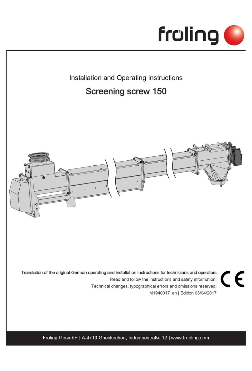
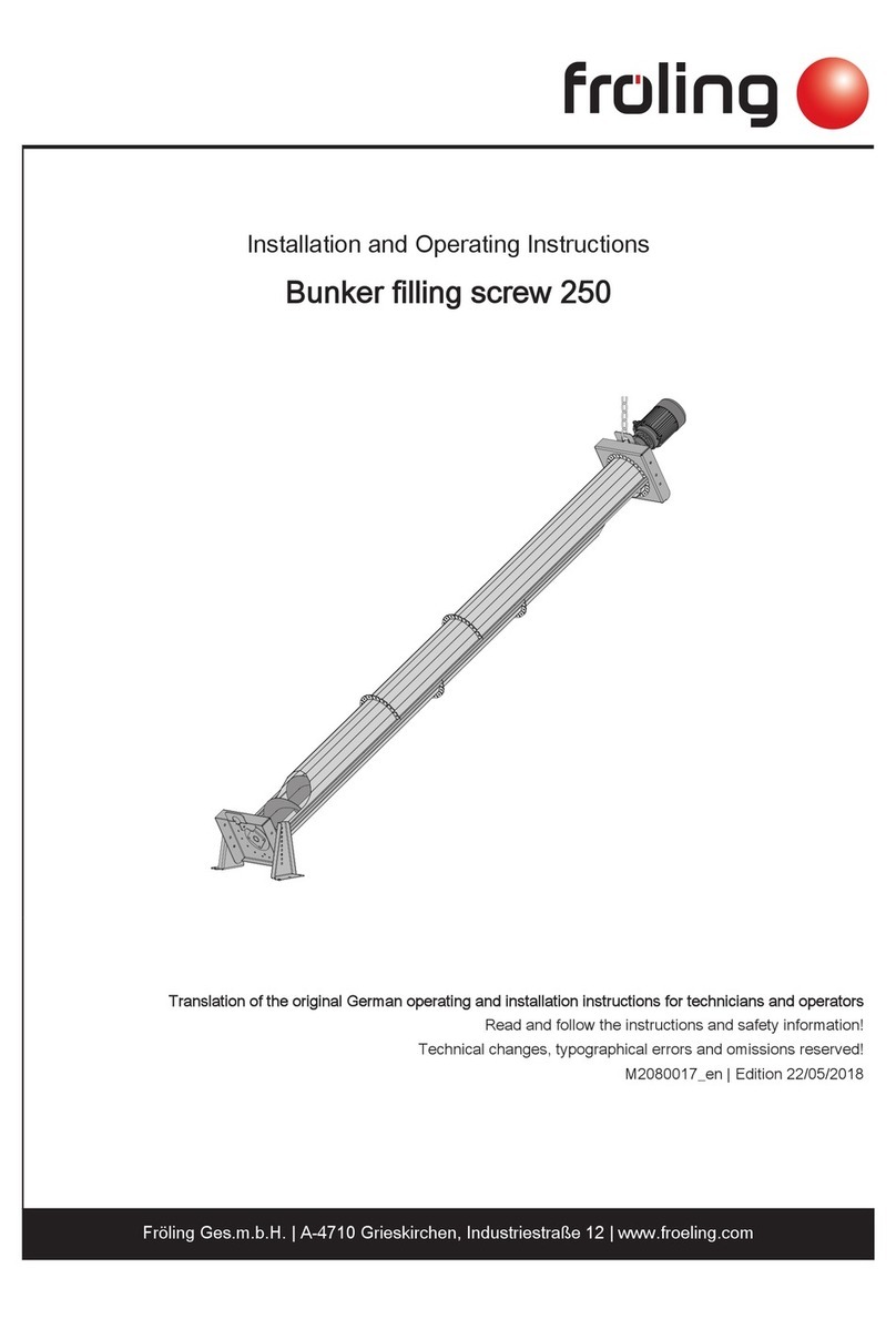
Fröling EF 250 User manual

Installation and Operating Instructions
Modular electrostatic precipitator system EF 250-500
EF 250 EF 500
Translation of the original German operating and installation instructions for technicians and operators
Read and follow the instructions and safety information!
Technical changes, typographical errors and omissions reserved!
M2140120_en | Edition 08/09/2020
Fröling GesmbH | A-4710 Grieskirchen, Industriestraße 12 | www.froeling.com

Table of contents
1 General 4
1.1 Operating principle 4
2 Safety 5
2.1 Hazard levels of warnings 5
2.2 Pictograms used 6
2.3 General safety information 7
2.4 Permitted uses 7
2.5 Qualification of staff 8
2.5.1 Qualification of assembly staff 8
2.5.2 Personal protective equipment for assembly staff 8
2.5.3 Qualification of operating staff 9
2.5.4 Protective equipment for operating staff 9
2.6 Chimney connection/chimney system 9
2.6.1 Measuring port 10
2.7 Residual risks 10
3 Design information 12
4 Technical information 13
4.1 Dimensions 13
4.2 Technical specifications 14
5 Assembly 15
5.1 Transport 15
5.2 Temporary storage 15
5.3 Positioning 16
5.4 Setting up in the boiler room 16
5.4.1 Removing the electrostatic precipitator system from the pallet 16
5.4.2 Recommended clearances in the boiler room 17
5.5 Adjusting the height of the ash container 18
5.6 Adapting the handle on the ash container 18
5.7 Fitting the flue gas temperature sensor 19
5.8 Adapting the electrostatic precipitator system (if required) 20
5.8.1 Modification of the ash container on the opposite side of the filter system 21
Removing the ash container and fittings
21
Removing the drive and fittings
22
Installing the drive and fittings on the opposite side
24
Installing the ash container and fittings on opposite side
26
5.8.2 Modification of the bypass flap drive on the opposite side 27
5.9 Installing the electrostatic precipitator system on Turbomat TM 31
5.10 Electrical connection 32
5.10.1 Establishing the connection line to the boiler 32
5.10.2 Potential equalisation 32
Table of contents
2 Fröling GesmbH | A-4710 Grieskirchen, Industriestraße 12 | www.froeling.com

6 Commissioning 33
6.1 Switching on the electrostatic precipitator system 33
6.2 Activating the electrostatic precipitator system on the controller 33
6.3 Check the direction of rotation of the ash screw 34
7 Operation / maintenance 35
7.1 Checking the fill level of the ash container and emptying if required 37
8 Periodic inspection and cleaning 38
8.1 Cleaning electrodes and the interior 38
9 Decommissioning 40
9.1 Disassembly 40
9.2 Disposal 40
10 Notes 41
11 Appendix 44
11.1 Addresses 44
11.1.1 Address of manufacturer 44
Customer service
44
11.1.2 Address of the installer 44
Table of contents
Installation and Operating Instructions EF 250-500 | M2140120_en 3

1 General
Thank you for choosing a quality product from Froling. The product features a state-of-
the-art design and conforms to all currently applicable standards and testing
guidelines.
Please read and observe the documentation provided and always keep it close to the
system for reference. Observing the requirements and safety information in the
documentation makes a significant contribution to safe, appropriate, environmentally
friendly and economical operation of the system.
The constant further development of our products means that there may be minor
differences from the pictures and content. If you discover any errors, please let us
know: [email protected].
Subject to technical change.
1.1 Operating principle
The modular electrostatic precipitator system operates on the electrostatic principle of
corona discharge.
The flue gas from the boiler flows together with the fine dust particles (1) produced
during combustion into the electrostatic precipitator system, where electrons (3) are
released from the high voltage electrodes (2), which electrostatically charge the dust
particles. The charged dust particles (4) then move towards the collecting electrode
(5) where they are removed. This filters a large proportion of fine dust particles out of
the flue gas.
At regular intervals, the fine dust particles are removed by lifting the cleaning baskets
and transported into the ash container.
1General
Operating principle
4 Fröling GesmbH | A-4710 Grieskirchen, Industriestraße 12 | www.froeling.com

2 Safety
2.1 Hazard levels of warnings
This documentation uses warnings with the following hazard levels to indicate direct
hazards and important safety instructions:
DANGER
The dangerous situation is imminent and if measures are not observed it will lead
to serious injury or death. You must follow the instructions!
WARNING
The dangerous situation may occur and if measures are not observed it will lead
to serious injury or death. Work with extreme care.
CAUTION
The dangerous situation may occur and if measures are not observed it will lead
to minor injuries.
NOTICE
The dangerous situation may occur and if measures are not observed it will lead
to damage to property or pollution.
Safety 2
Hazard levels of warnings
Installation and Operating Instructions EF 250-500 | M2140120_en 5

2.2 Pictograms used
The following symbols are used in the documentation and/or on the electrostatic
precipitator system to show what is required and forbidden and to give warnings.
In accordance with the Machinery Directive, signs fitted directly within the danger area
of the electrostatic precipitator system indicate immediate hazards or safety
procedures. These stickers must not be removed or covered.
Refer to the operating
instructions
Wear safety shoes
Wear protective gloves Turn off the main switch
Wear a dust mask Wear suitable protective clothing
Unauthorised access prohibited Prohibited for persons with
pacemakers
Warning - hot surface Warning - hazardous electrical
voltage
Warning - hazardous or irritant
materials
Hand injury warning
Warning of injury to fingers or
hands, automatic screw
2Safety
Pictograms used
6 Fröling GesmbH | A-4710 Grieskirchen, Industriestraße 12 | www.froeling.com

2.3 General safety information
DANGER
If the device is used incorrectly:
Incorrect use of the system can cause severe injury and damage.
When operating the system:
❒ Observe the instructions and information in the manuals
❒ Observe the details on procedures for operation, maintenance and cleaning,
as well as troubleshooting in the respective manuals.
❒ Any work above and beyond this (e.g. servicing) must be carried out by a
heating engineer approved by Fröling Heizkessel- und Behälterbau GesmbH
or by Froling customer services
CAUTION
Assembly and installation by unqualified persons:
Risk of personal injury and damage to property
During assembly and installation:
❒ Observe the instructions and information in the manuals
❒ Only allow appropriately qualified personnel to work on the system
2.4 Permitted uses
The Froling electrostatic precipitator system may only be used for treating exhaust
gases in conjunction with the following Froling heating systems:
▪Electrostatic precipitator system EF 250:
– Turbomat TM 150-250
▪ Electrostatic precipitator system EF 500:
– Turbomat TM 320
– Turbomat TM 400-500
The electrostatic precipitator system is integrated between the boiler and the flue gas
system with the boiler induced draught needing to be connected to the precipitator
outlet. Use only the fuels specified in the intended use section for each heating system
may be used.
The Froling electrostatic precipitator system is not permitted for use in hazardous
areas!
The unit should only be operated when it is in full working order. It must be operated in
accordance with the instructions, observing safety precautions, and you should ensure
you are aware of the potential hazards. The inspection and cleaning intervals in the
operating instructions must be observed. Ensure that any faults which might impair
safety are rectified immediately.
The manufacturer or supplier is not liable for any damage resulting from non-permitted
uses.
Safety 2
General safety information
Installation and Operating Instructions EF 250-500 | M2140120_en 7
Only original spare parts or specific alternative spare parts authorised by the
manufacturer may be used. Any kind of change or modification made to the product
will invalidate the manufacturer’s conformity with the applicable guideline(s). In such
cases, the product will need to undergo new hazard evaluation procedures by the
operator. The operator will then be fully responsible for the declaration of conformity
according to the valid guideline(s) for the product and will need to issue a
corresponding declaration for the device. This person will then assume all of the rights
and responsibilities of a manufacturer.
2.5 Qualification of staff
2.5.1 Qualification of assembly staff
CAUTION
Assembly and installation by unqualified persons:
Risk of personal injury and damage to property
During assembly and installation:
❒ Observe the instructions and information in the manuals
❒ Only allow appropriately qualified personnel to work on the system
Assembly, installation, initial startup and servicing must always be carried out by
qualified personnel:
- Heating technician / building technician
- Electrical installation technician
- Froling customer services
The assembly staff must have read and understood the instructions in the
documentation.
2.5.2 Personal protective equipment for assembly staff
You must ensure that staff have the protective equipment specified by accident
prevention regulations.
▪ For transportation, setup and assembly:
- suitable work wear
- protective gloves
- sturdy shoes (min. protection class S1P)
2Safety
Qualification of staff
8 Fröling GesmbH | A-4710 Grieskirchen, Industriestraße 12 | www.froeling.com

2.5.3 Qualification of operating staff
CAUTION
If unauthorised persons enter the Installation room / boiler room:
Risk of personal injury and damage to property
❒ The operator is responsible for keeping unauthorised persons, in particular
children, away from the system.
Only trained operators are permitted to operate the unit. The operator must also have
read and understood the instructions in the documentation.
2.5.4 Protective equipment for operating staff
You must ensure that staff have the protective equipment specified by accident
prevention regulations!
▪ For operation, inspection and cleaning:
–Suitable work wear
– Protective gloves
– Sturdy shoes
– Dust mask
When working with dust from the electrostatic
particle separator, use dust masks in filter class
FFP2 or higher
2.6 Chimney connection/chimney system
The entire flue gas system must be designed to prevent, wherever possible, damage
caused by seepage and insufficient feed pressure. Raw gas temperatures below 65°C
are not permitted in order to avoid condensation.
The chimney connection should be as short as possible. The upward incline of the
connection should not exceed 30 - 45°. Insulate the connecting piece on site. The
entire flue gas system i.e. chimney and connection should be calculated in
accordance with EN 13384-1.
Local regulations and other statutory regulations also apply.
NOTICE! The chimney must be authorised by a smoke trap sweeper or chimney
sweep.
Safety 2
Qualification of staff
Installation and Operating Instructions EF 250-500 | M2140120_en 9

2.6.1 Measuring port
For measuring the emissions of the system, a suitable measuring port must be
installed in the connecting piece between the electrostatic precipitator system and
chimney system.
D
D
M
2 x D
In front of the measuring port (M) a straight inlet section should be located at a
distance corresponding to about twice the diameter (D) of the connecting piece. A
straight outlet section at a distance corresponding to about the single diameter of the
connecting piece should be provided after the measuring port. The measuring port
must remain closed whenever the system is in operation.
The diameter of the measuring probe used by Froling customer service is 14 mm. To
avoid measuring errors due to the ingress of false air, the diameter of the measuring
port must not exceed 21 mm.
2.7 Residual risks
DANGER
If maintenance work is performed when the system is in operation:
Risk to life from high voltage electrodes!
Before carrying out work on/in the electrostatic precipitator:
❒ Switch off the power supply and take precautions to prevent accidental
switching on
❒ Earth and short circuit HV electrodes
❒ Always have work carried out by a qualified electrician
❒ Observe the applicable standards and regulations
➥Work must not be carried out on electrical components by unauthorised
persons
2Safety
Chimney connection/chimney system
10 Fröling GesmbH | A-4710 Grieskirchen, Industriestraße 12 | www.froeling.com

WARNING
When touching hot surfaces:
There is a risk of serious burns at hot surfaces and at the flue gas pipe
connection!
Take the following precautions when working on the electrostatic precipitator:
❒ Shut down the boiler according to procedure, switch off the electrostatic
precipitator and allow the whole system to cool
❒ Always wear protective gloves when working on the system
❒ Insulate the flue gas pipes and do not touch them during operation
CAUTION
Opening the control cabinet when the electrostatic precipitator system is switched
off but the boiler is switched on:
Possible electric shock by 24V DC control signal of the boiler!
Before working on/in the electrostatic precipitator system:
❒ Shut down the boiler according to procedure
❒ Switch off the power supply to the boiler and take precautions to prevent
accidental switching on
❒ Always have work carried out by a qualified electrician
➥Work must not be carried out on electrical components by unauthorised
persons
DANGER
Persons with pacemakers in the immediate vicinity of the system:
Possible interference of the pacemaker by electromagnetic fields of the
electrostatic precipitator system!
Therefore:
❒ Maintain a safety distance of at least one metre from the electrostatic
precipitator system
❒ Perform work only when the electrostatic precipitator system is switched off
Safety 2
Residual risks
Installation and Operating Instructions EF 250-500 | M2140120_en 11

3 Design information
Boiler room characteristics
▪ The floor must be even, clean and dry and have an adequate load-bearing
capacity.
▪There must be no explosive atmosphere in the boiler room as the system is not
suitable for use in a potentially explosive environment.
▪ The boiler room must be frost-free.
▪ The system does not provide any light, so the customer must provide sufficient
lighting in the boiler room in accordance with national workplace design
regulations.
▪ When using the system above 2000 metres above sea level you should consult
the manufacturer.
▪ Danger of fire due to flammable materials.
The floor of the system must not be flammable. No flammable materials should be
stored near the system. Flammable objects (e.g. clothing) must not be put on the
system to dry.
▪ Damage due to impurities in combustion air.
Do not use any solvents or cleaning agents containing chlorine and hydrogen
halides in the installation room of the system (e.g. chlorination units for swimming
pools).
▪ The system must be protected against the chewing or nesting of animals (e.g.
rodents etc.).
3Design information
Boiler room characteristics
12 Fröling GesmbH | A-4710 Grieskirchen, Industriestraße 12 | www.froeling.com

4 Technical information
4.1 Dimensions
L
L1
L2
B
B1
H
H2
H1
D
L
L1
L2
B
B1
H
H2
H1
D
Item Description Unit Electrostatic precipitator system
EF 250 EF 500
B Total width incl. ash container handle mm 845 1301
B1 Width of electrostatic precipitator system 730 1070
L Total length incl. fittings 1873
L1 Length without container 1589
L2 Length of electrostatic precipitator
system
1275
H Height of electrostatic precipitator
system
1950
H1 Height of clean gas outlet connection 1578
H2 Height of raw gas inlet connection 1178
D Flue spigot diameter (outside) 180 350
EF 250:
EF 500:
Technical information 4
Dimensions
Installation and Operating Instructions EF 250-500 | M2140120_en 13

4.2 Technical specifications
Description Electrostatic precipitator system
EF 250 EF 500
Electrical connection 400 V / 50 Hz / fused C13A
Power consumption W 200 300
Insulation thickness mm 50
Weight kg 460 720
Efficiency (separation rate) up to 85%
Volume of ash container l 50 2 x 50
Diameter of flue gas connection (outside) mm 180 350
Max. electrode voltage V 30,000
Max. permitted boiler flue gas temperature °C 200
Minimum filter inlet temperature °C 90
Minimum filter outlet temperature °C 65
Maximum ambient temperature in installation
room
°C 35
Reduction of flue gas temperature in filter K 20
Max. permitted nominal output kW 250 500
Max. permitted flue gas mass flow g/s 195 390
Max. permitted flue gas flow rate m³/h 820 1645
Fluidic resistance Pa 145 120
4Technical information
Technical specifications
14 Fröling GesmbH | A-4710 Grieskirchen, Industriestraße 12 | www.froeling.com

5 Assembly
Assembly, installation and initial startup of the electrostatic precipitator system must
only be carried out by qualified staff.
CAUTION
Assembly and installation by unqualified persons:
Risk of personal injury and damage to property
During assembly and installation:
❒ Observe the instructions and information in the manuals
❒ Only allow appropriately qualified personnel to work on the system
5.1 Transport
The product is delivered on pallet(s).
NOTICE
Possibility of damage to components if handled incorrectly
❒Follow the transport instructions on the packaging
❒ Transport components with care to avoid damage
❒ Protect components against damp
❒ Pay attention to the pallet's centre of gravity when lifting
5.2 Temporary storage
If the system is to be assembled at a later stage:
❒Store components at a protected location, which is dry and free from dust
➥Damp conditions and frost can damage components, particularly electric ones!
Assembly 5
Transport
Installation and Operating Instructions EF 250-500 | M2140120_en 15

5.3 Positioning
❒ Position a fork-lift or similar lifting device at the pallet and bring in the components
If the electrostatic precipitator system cannot be brought in on the pallet:
❒Remove system from pallet
⇨ See "Removing the electrostatic precipitator system from the pallet" [page 16]
Positioning using a crane:
❒ Loosen screws and remove the top cover
❒Hook the crane hook onto the crane eyelets and position the electrostatic
precipitator system
5.4 Setting up in the boiler room
5.4.1 Removing the electrostatic precipitator system from the pallet
❒ Remove the transport locks and lift the electrostatic precipitator system from the
pallet
❒Place the electrostatic precipitator system in the desired location
➥Observe the maintenance areas
⇨ See "Recommended clearances in the boiler room" [page 17]
5Assembly
Positioning
16 Fröling GesmbH | A-4710 Grieskirchen, Industriestraße 12 | www.froeling.com

5.4.2 Recommended clearances in the boiler room
▪ The system should generally be set up so that it is accessible from all sides
allowing quick and easy maintenance.
▪Regional regulations regarding necessary maintenance areas for inspecting the
chimney should be observed in addition to the specified distances!
▪ Observe the applicable standards and regulations when setting up the system.
▪ Observe additional standards for noise protection!
(ÖNORM H 5190 - Noise protection measures)
EF 250 EF 500
A
B
C
A
C
B
D
Description
A Ash container maintenance area 200 mm
B Left maintenance area 400 mm
C Geared motor maintenance area 200 mm
DRight maintenance area 1) 400 mm
1.Only for electrostatic precipitator system EF 500
Assembly 5
Setting up in the boiler room
Installation and Operating Instructions EF 250-500 | M2140120_en 17

5.5 Adjusting the height of the ash container
❒ Pull out the spring cotter on the transport wheels and adjust the height
➥The wheels rest on the ground when the ash container is mounted!
❒Remove the ash container from the electrostatic precipitator system and align it
horizontally with the adjustable foot
5.6 Adapting the handle on the ash container
The ash container can be pulled or carried depending on the situation.
❒ Remove the pipe locking pin on the ash container
❒Insert the handle with carrying bar on the side of the ash container
❒ Push the second handle onto the carrying bar and secure it with the pipe locking
pin
5Assembly
Adjusting the height of the ash container
18 Fröling GesmbH | A-4710 Grieskirchen, Industriestraße 12 | www.froeling.com

5.7 Fitting the flue gas temperature sensor
❒ Insert the flue gas temperature sensor completely into the brass bushing on the
lower flue pipe connection and secure with a wing screw
❒Run the flue gas temperature sensor cable to the boiler controller and connect it
according to the enclosed wiring diagram, ⇨ See "Electrical connection" [page
32]
Assembly 5
Fitting the flue gas temperature sensor
Installation and Operating Instructions EF 250-500 | M2140120_en 19

5.8 Adapting the electrostatic precipitator system (if required)
The following components of the electrostatic precipitator system can be installed on
the opposite side:
▪Ash container
⇨ See "Modification of the ash container on the opposite side of the filter system"
[page 21]
▪ Bypass flap drive
⇨ See "Modification of the bypass flap drive on the opposite side" [page 27]
Electrostatic precipitator system EF 250 Electrostatic precipitator system EF 500
The flue pipe flanges can be mounted on all sides shown. As a general rule, the raw
gas inlet is always in the lower area, the clean gas outlet in the upper area. These
connections can be positioned according to the requirements and do not have to be
arranged one above the other.
NOTICE! If modification work is to be carried out, it is recommended that the filter is
not installed in the desired position until the work has been completed in order to have
sufficient all-round space.
The following modification work shows the necessary steps on an EF 250 electrostatic
precipitator system. Unless otherwise stated, all work on an EF 500 electrostatic
precipitator system must be carried out in the same way.
5Assembly
Adapting the electrostatic precipitator system (if required)
20 Fröling GesmbH | A-4710 Grieskirchen, Industriestraße 12 | www.froeling.com
This manual suits for next models
1
Table of contents
Other Fröling Industrial Equipment manuals

Fröling
Fröling Screening screw 150 User manual

Fröling
Fröling T4e User manual

Fröling
Fröling TM 320 User manual

Fröling
Fröling Lambdamat LM 800 User manual

Fröling
Fröling FBR-G User manual

Fröling
Fröling BFSV User manual

Fröling
Fröling GAR 110 User manual

Fröling
Fröling TGR 110 User manual

Fröling
Fröling 250 User manual

Fröling
Fröling BFSU User manual