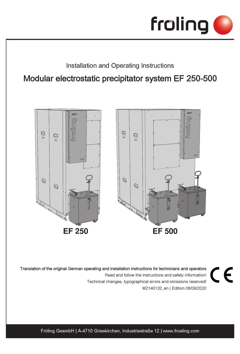
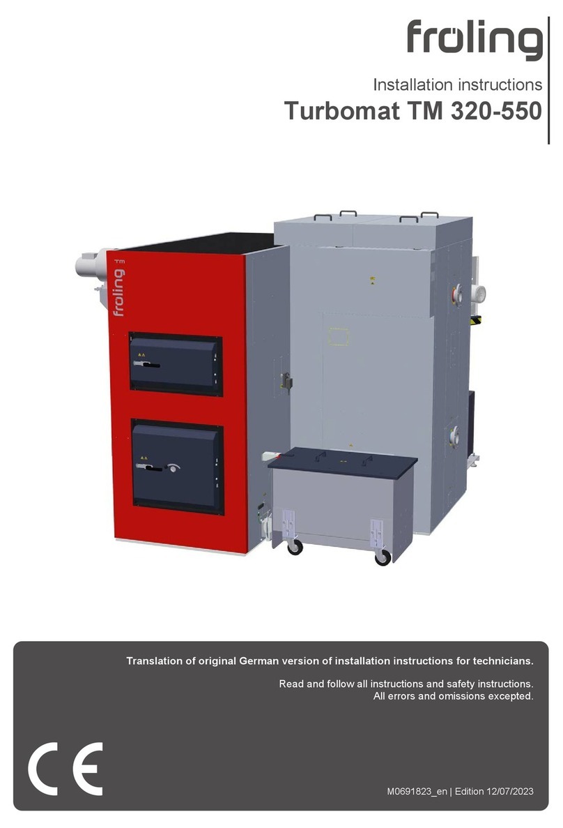
Fröling Turbomat 320 User manual

Operating Instructions
Turbomat 320/500
Read and follow the operating instructions and safety information.
Edition: 11/2004
Fröling Boiler and Container Making GmbH, Industriestraße 12, A-4710 Grieskirchen
Tel. +43 (0) 7248 606-0 Fax +43 (0) 7248 606-600 info@froeling.com www.froeling.com

Table of Contents
page 2 a
B 034 00 04 a
I
Table of Contents
1Product overview 4
2General information 6
2.1 Permitted uses 6
2.1.1 Permitted fuel ............................................................................................................... 6
2.1.2 Who May Operate the Boiler......................................................................................... 6
2.2 Design information 7
2.2.1 Official approval and reporting obligations .................................................................... 7
2.2.2 Domestic hot water requirements.................................................................................. 7
2.3 Safety devices 8
2.4 Residual risks 10
2.5 Emergency actions 11
3Operating the system 12
3.1 Starting up for the first time 12
3.1.1 Checking the heating system...................................................................................... 12
3.2 Heating up the boiler 12
3.2.1 Switching on the system ............................................................................................. 12
3.2.2 Switching on the boiler................................................................................................ 12
Heating with the automatic igniter .......................................................................... 12
Heating without the automatic igniter...................................................................... 13
3.2.3 Controlling the boiler................................................................................................... 13
3.2.4 Switching off the boiler................................................................................................ 13
3.2.5 Switching off the system ............................................................................................. 13
4Boiler maintenance 14
4.1 Inspection, cleaning, and maintenance 15
4.1.1 Maintenance schedule for Turbomat 320.................................................................... 16
Emptying theash can.............................................................................................. 23
4.1.2 Maintenance schedule for safety devices.................................................................... 24
4.2 Summer service 25
5Troubleshooting 26
5.1 External faults 26
5.2 Internal boiler faults 26
5.2.1 Resetting the safety temperature limiter (STB)............................................................ 26
5.2.2 Acknowledging a fault message.................................................................................. 26

Table of Contents
Fröling Boiler and Container Making GmbH, Industriestraße 12, A-4710 Grieskirchen page 3
Tel. +43 (0) 7248 606-0 Fax +43 (0) 7248 606-600 info@froeling.com www.froeling.com Edition: 02.06.2005
I
6Appendix 27
6.1 Preparing to test emissions 27
6.2 Maintenance instructions for hydraulic equipment 28
6.3 Addresses 29
6.3.1 Manufacturer's address .............................................................................................. 29
6.3.2 Your Installer's Address .............................................................................................. 29
6.4 Declaration of Conformity 30
6.5 Your notes 31

Product Overview
page 4 a
B 034 00 04 a
1
Dear Customer,
Congratulations on choosing a quality product from FRÖLING.
The FRÖLING Turbomat is a state-of-the-art design that conforms to all currently applicable
standards and testing guidelines.
Please read and observe the operating instructions and always keep them available in close
proximity to the boiler. They contain safety information and all the operation and maintenance
specifications needed to operate the boiler safely, properly, and economically.
1 Product overview
Pos. Description
1 Waste wood boiler –Fröling Turbomat 320 kW or 500 kW
2 Tunnel door
3 Combustion chamber door
4 Mobile ashcan; Automatic ash removal - combustion chamber
5 Two-piece ashcan; Automatic ash removal - heat exchanger
6 Switch gear cabinet with integrated controller
7 Selector switch for induced draught fan:
AUTO: The induced draught fan is switched on and off by the controller.
0: The induced draught fan is switched off.
MANUAL: The induced draught fan is switched on and off by the operator and not by the
controller.
8 Main switch: switches the system on and off
9 Lambdatronic H 3000 controller
10 LED indicating operating status:
Long green blinking: boiler activated
Short green blinking: boiler deactivated
Red blinking: Fault
11 Two-row display showing: operating mode, operating status, parameters, ...
12 START key: switches on boiler
13 STOP key: switches off boiler
14 Temperature selector: selects temperature setpoint
15 BACK key: returns you to a previous menu, undoes a data entry
16 PLUS key: moves the arrow up, increases or activates a parameter
17 MINUS key: moves the arrow down, decreases or deactivates a parameter
18 ENTER key: takes you to a submenu, calls up or confirms entries

Product Overview
Fröling Boiler and Container Making GmbH, Industriestraße 12, A-4710 Grieskirchen page 5
Tel. +43 (0) 7248 606-0 Fax +43 (0) 7248 606-600 info@froeling.com www.froeling.com Edition: 02.06.2005
1
8
9
10
11
12
13
14 15
16
17
18
7
1
2
3
4
5
6

General Information
Permitted Uses
page 6 a
B 034 00 04 a
2
2 General information
2.1 Permitted uses
The boiler should only be operated when it is fully efficient. The boiler should be operated in
accordance with the instructions given in this manual. Implement all the necessary safety
precautions. Before you start using the boiler, make sure that you are aware of the potential
hazards involved. Ensure that any malfunctions, which might impact safety are traced any
removed immediately.
The Turbomat is designed exclusively for heating domestic water. Only use the fuels
specified below 2.1.1.
The manufacturer or supplier are not liable for any damages resulting from non-
permitted uses.
2.1.1 Permitted fuel
For Germany: waste-wood conforming to 1. BImSchV of 15 July 1988
For Austria: waste-wood conforming to ÖNORM M 7133
Designation Description
W20 air dried
W30 requires storage
W35 requires limited storage
W40 damp
Water content
W50 wet
G30 Fine waste-wood (for screw feeders)
G50 Medium waste-wood (for screw feeders)
Size
G100 Large waste-wood (for hydraulic feeders only)
IMPORTANT
Corrosive deposits. Do not burn non-approved fuels. Do not operate at low temperatures which
cause condensation. Burning non-approved fuels will cause a build up of corrosive deposits.
Condensation also corrodes.
Operating under these conditions will void your guarantee. May cause
damage or corrosion in the combustion chamber.
2.1.2 Who May Operate the Boiler
Only trained operators are permitted to operate the boiler.
IMPORTANT
No unauthorized access to the boiler room.
Hazard: Personal injury and damage to property.
It is the responsibility of the operator to ensure that unauthorized persons, especially
children, are kept away from the boiler.

General Information
Design Information
Fröling Boiler and Container Making GmbH, Industriestraße 12, A-4710 Grieskirchen page 7
Tel. +43 (0) 7248 606-0 Fax +43 (0) 7248 606-600 info@froeling.com www.froeling.com Edition: 02.06.2005
2
2.2 Design information
As a rule, the operator is not authorized to modify or disable the safety equipment.
In addition to the operating instructions and the applicable regulations for the country in which
the boiler will be operated, all fire, police, and electrical regulations must be observed.
2.2.1 Official approval and reporting obligations
NOTE
Each heating system must be officially approved.
In Austria:
- New installations must be reported to the local building or police authorities.
In Germany:
- Report new installations to an approved chimney sweep and to the building authorities.
2.2.2 Domestic hot water requirements
There are no special requirements for domestic hot water supplies.
Applicable standards:
Austria: ÖNORM H 5195, ÖNORM H 5195-2
Germany: VDI 2035
If the system is topped up or refilled:
Prepare (soften) the water to prevent boiler scaling.

General Information
Safety devices
page 8 a
B 034 00 04 a
2
2.3 Safety devices
B
C
3
4
1
A
2
5
7
6

General Information
Safety Devices
Fröling Boiler and Container Making GmbH, Industriestraße 12, A-4710 Grieskirchen page 9
Tel. +43 (0) 7248 606-0 Fax +43 (0) 7248 606-600 info@froeling.com www.froeling.com Edition: 02.06.2005
2
Pos. Component Description
1 Main switch Before maintenance: Switch off the entire system
All components are switched off and powered
down
2 STOP key In the event of over-heating, shuts down boiler
The pumps continue to run.
IMPORTANT: To stop heating operations,
always use the STOP key only.
Do not use the main switch.
3 Door contact switch, tunnel door
4 Door contact switch, combustion
chamber door
If you open the door while the boiler is operating, switch
the induced draught fan to full speed.
5 Safety overload switches, motor
overload switch
Switch off the related component in the event of fault
currents or overloads.
6 Power supply fuses
7 Motherboard fuses
Properly fuse the control system and any electronic
components
When changing fuses, fit fuses with the rated
current specified.
Devices for preventing the boiler from over-heating:
A Boiler controller Switches the boiler off if the boiler temperature is set 5°C
(standard) above the setpoint value.
B Safety temperature limiter (STB) Switches off the blower fan at the maximum boiler
temperature of 100 °C. The pumps continue to run.
Once the temperature falls to below 95 °C, the STB can
be reset mechanically
Unscrew the cap on the safety temperature limiter
Using a screwdriver, press the reset button
C Safety battery valve Opens at a temperature of 105 °C and feeds cold water to
the safety heat exchanger (safety battery).
D Safety valve (not illustrated,
provided by the customer)
When the boiler pressure is too high, the safety valve
opens and vents off the hot water as steam.
Before you start up the system again, top up the
system to replace any water which has been lost
through venting.

General Information
Residual risks
page 10 a
B 034 00 04 a
2
2.4 Residual risks
IMPORTANT
Do not touch hot surfaces and flue gas pipes.
Burns hazard
Only operate the boiler using the handles provided for this purpose.
Insulate the flue gas pipes or simply avoid touching them during operation.
IMPORTANT
Do not open the combustion chamber door during operation.
Equipment damage hazard.
Opening the door during operation will cause a loss of draught in the combustion chamber.
Flash fire hazard
Increase the speed of the induced draught fan to the maximum to compensate for any
loss of draught. Dust can be sucked up by the chimney and expelled into the open air.
Take the following precautions:
Only open the door when a fault is present
Before starting any maintenance work:
Turn the induced draught selector switch to the "0" (OFF) position.
Switch off the boiler and allow it to cool down.
IMPORTANT
Do not use unauthorized fuel types.
Equipment damage hazard.
Only use permitted fuels.
See 2.1.1 Permitted fuel
IMPORTANT
Failure to observe specified cleaning and maintenance intervals.
Equipment damage hazard.
This will void your guarantee.
Failure to observe the specified cleaning and maintenance intervals can cause hazardous
operating conditions (e.g. blow-back, flash fires).
Your guarantee will not cover damage caused in these circumstances.

General Information
Emergency actions
Fröling Boiler and Container Making GmbH, Industriestraße 12, A-4710 Grieskirchen page 11
Tel. +43 (0) 7248 606-0 Fax +43 (0) 7248 606-600 info@froeling.com www.froeling.com Edition: 02.06.2005
2
2.5 Emergency actions
If the system over-heats and the safety devices fail to operate, proceed as follows:
Close all the doors on the boiler.
Shut down the boiler by pressing the STOP key.
Do not use the main switch.
Open all mixer taps. Switch on all pumps.
Leave the boiler room and close the door.
Try to increase heat consumption by turning on all radiators and other appliances.
If the temperature does not drop:
Contact an installer or Fröling Customer Service.
See 6.3.1 Manufacturer's address

Operating the System
Starting up for the first time / Heating the boiler
page 12 a
B 034 00 04 a
3
3 Operating the system
3.1 Starting up for the first time
NOTE
The initial start-up must be carried out by an authorized installer or by the Fröling
Customer Service department.
3.1.1 Checking the heating system
Check that there is sufficient water in the heating system.
Check that the heating system has been completely vented.
Check that all the safety devices are correctly fitted and are fully efficient.
See 2.3 Safety devices
Check that there is sufficient ventilation and venting.
See the set-up instructions for the Turbomat 320/500.
3.2 Heating up the boiler
3.2.1 Switching on the system
Turn the mains switch (1) on the switch gear cabinet to
ON.
When the controller has completed the self-test and
system check, the boiler is ready for operation.
3.2.2 Switching on the boiler
Heating with the automatic igniter
Press the START key (2).
Fuel will be fed into the combustion chamber and
heated by the igniter fan.
The heating system is controlled via the control
system according to the selected mode.
1
2

Operating the System
Starting up for the first time / Heating the boiler
Fröling Boiler and Container Making GmbH, Industriestraße 12, A-4710 Grieskirchen page 13
Tel. +43 (0) 7248 606-0 Fax +43 (0) 7248 606-600 info@froeling.com www.froeling.com Edition: 02.06.2005
3
Heating without the automatic igniter
Turn the induced draught selector switch (3) to the "0"
position.
Open the combustion chamber door.
Place paper, cardboard or wood on the grate and ignite
this.
Close the combustion chamber door.
Turn the induced draught selector switch (3) to the
"AUTO" position.
Press the START key (2).
The heating system is controlled via the control
system according to the selected mode.
3.2.3 Controlling the boiler
Necessary control steps. Displaying or modifying parameters:
See the instruction manual for the Lambdatronic H 3000.
3.2.4 Switching off the boiler
Press the STOP key (4).
The boiler follows the shut-down program and
switches to the "OFF" status.
The heating system is no longer controlled via the
control system.
Always stop the boiler using the STOP switch.
The pumps must continue to run for 6 hours.
3.2.5 Switching off the system
IMPORTANT! Only switch off when the boiler has
cooled down.
Switch off the main switch (1) on the controller.
The controller is switched off.
All the system components (drive, induced draught
fan, pumps,...) are powered down.
2
4
1
3

Boiler Maintenance
Cleaning and Maintenance
page 14 a
B 034 00 04 a
4
4 Boiler maintenance
IMPORTANT
Maintenance when the boiler is hot.
Burns hazard. Hot components.
Before starting maintenance on the boiler:
Shut down the boiler using the STOP key and allow it to cool down.
Turn the induced draught selector switch to the "0" position.
IMPORTANT
Working on electrical components.
Hazard - Risk of electric shock
Shut down the boiler using the STOP key and allow it to cool down.
Switch off the main switch and take precautions to prevent accidental switching on.
Work on electrical components must only be carried out by authorized skilled
electricians.
IMPORTANT
Failure to observe specified cleaning and maintenance intervals.
Equipment damage hazard.
This will void your guarantee.
Failure to observe the specified cleaning and maintenance intervals can cause hazardous
operating conditions (e.g. blow-back, flash fires).
Your guarantee will not cover damage caused in these circumstances.

Boiler Maintenance
Cleaning and Maintenance
Fröling Boiler and Container Making GmbH, Industriestraße 12, A-4710 Grieskirchen page 15
Tel. +43 (0) 7248 606-0 Fax +43 (0) 7248 606-600 info@froeling.com www.froeling.com Edition: 02.06.2005
4
IMPORTANT
Cleaning the combustion chamber with the combustion chamber temperature sensor already
mounted.
Hazard. Risk of damage to thermocouple.
Before you start to clean the combustion chamber:
Mark the position of the thermocouple.
Loosen the clamps and pull out the thermocouple.
After maintenance:
Carefully clean any tar or soot deposits from the thermocouple.
Re-insert the thermocouple to the position marked previously and fix in place with the
clamps.
4.1 Inspection, cleaning, and maintenance
For cleaning and maintenance use the cleaning kit provided. The
cleaning kit consists of:
- Chamber plate (triangular plate)
- Flat scraper
- Large brush (Ø 81 mm)
- Small brush (Ø 53 mm)
We recommend that you also use an
industrial vacuum cleaner.

Boiler Maintenance
Cleaning and Maintenance
page 16 a
B 034 00 04 a
4
4.1.1 Maintenance schedule for Turbomat 320
T(D) = Daily, W = Weekly, M = Monthly, VJ(3-M) = Every 3 months , HJ(6-M) = Every six months, J(Y) = Annually
No. Component / Maintenance Operation Interval
1 Chamber + heat exchanger
2 Induced draught fan + flue gas return (FGR)
3 Combustion air blower fan
Overall visual inspection
Clean all components where necessary
Change defective components immediately.
D
4 Gear motors Check all gear motors for oil leaks.
5 Heat-exchanger ash removal
6 Ash removal chamber
Check the ash level.
Empty the ashcan where necessary.
See page 23, Emptying theash can
W

Boiler Maintenance
Cleaning and Maintenance
Fröling Boiler and Container Making GmbH, Industriestraße 12, A-4710 Grieskirchen page 17
Tel. +43 (0) 7248 606-0 Fax +43 (0) 7248 606-600 info@froeling.com www.froeling.com Edition: 02.06.2005
4
No. Component / Maintenance Operation Interval
7 Combustion chamber
Using the flat scraper and
working from the tunnel
door, pull the ash on the
upper side of middle vault
towards you.
Using the flat scraper and
working from the tunnel
door, push the ash on the
upper side of the lower
vault towards the rear.
Using the flat scraper, pull
the ash on the combustion
chamber grate towards
you.
On the "Test Mode" menu, switch on the ash removal screws so that the ash which has
fallen into the ashcan is fed out. If your system is not fitted with automatic ash removal, you
must shovel the ash out of the chamber by hand.
The ash removal screws of the heat exchanger ash removal system will also operate at
the same time.
Empty the ashcans.
See page 23, Emptying theash can
8 Conveyor grate
Check the conveyor grate for dirt and obstructions (nails,
stones, slag,...). Clean where necessary.
The primary air slots must be free and unobstructed.
Check the grate, grate shafts and grate bearings for wear
and deformation
Change any worn or deformed components.
Check the grate drive for dirt and deposits.
M
9 Flue gas sensor
Loosen the retaining screw and pull out the flue gas sensor.
Using a clean cloth, wipe off the sensor.
Insert the flue gas sensor back into the flue gas pipe and
finger-tighten the retaining screw
3-M

Boiler Maintenance
Cleaning and Maintenance
page 18 a
B 034 00 04 a
4
No. Component / Maintenance Operation Interval
10 Lambda probe
Unscrew and remove the lambda probe and clean with a clean
cloth.
Refit and finger-tighten the lambda probe.
11 Conveyor grate
In the chamber opposite the heat exchanger:
Remove the cover from the cleaning hatch.
Remove the cleaning cover.
Check the grate and ash rakes for dirt and deposits. Clean where necessary.
3-M
12 Flue gas return (FGR) (optional)
Remove the pipe insulation from the inspection cover.
Unscrew the wing nuts from the inspection cover and remove the
cover.
Check the pipe for dirt and deposits. Clean where necessary.
13 Servomotors, drives, door contact switch
Visually inspect operation of the drives of the feed and ash removal
screws and the grate.
Check the efficiency of the door contact switch.
When the door is opened, the induced draught unit must operate
at full speed.
Check the efficiency of the air flap servo motors:
Press the reset button on the servo motor to release the air flap.
Hold the reset button pressed down.
Turn the air flap to the left-hand endstop.
Release the test knob.
The air flap must return automatically to its original position.
6-M

Boiler Maintenance
Cleaning and Maintenance
Fröling Boiler and Container Making GmbH, Industriestraße 12, A-4710 Grieskirchen page 19
Tel. +43 (0) 7248 606-0 Fax +43 (0) 7248 606-600 info@froeling.com www.froeling.com Edition: 02.06.2005
4
No. Component / Maintenance Operation Interval
14 Heat exchanger
Open the two heat exchanger covers.
Remove all dirt and deposits for the flue gas chamber.
Use a vacuum
cleaner for this job.
1. flue:
Remove the cover from the combustion pipe.
Clean the cover, the pipe and the burn-out opening (1) between
the chamber and the heat exchanger.
Refit the cover.
2. flue:
Check that the automatic heat exchanger cleaning system operates
smoothly.
Check the area for dirt and deposits.
If necessary, pull the entire system out of the heat exchanger pipes and
then clean the pipes and the Wirbulators with a brush.
3. flue:
Clean the inside of the dust
separator pipe with the small brush.
Pull out the dust separator pipe and
clean it.
Refit the pipe after you have
cleaned the fourth flue.
4th flue:
Dismantle the pipe retaining plate.
Under the plate, clean the flue gas chamber and
the connecting pipe to the induced draught fan.
Clean the heat exchanger pipes with the large
brush.
6-M
1

Boiler Maintenance
Cleaning and Maintenance
page 20 a
B 034 00 04 a
4
No. Component / Maintenance Operation Interval
15 Heat exchanger ash removal
Remove the ashcan of the heat exchanger ash removal unit.
Dismantle the two-piece ash removal flange.
Remove dirt and deposits from the sloping plates and from the ash screws.
6-M
16 Combustion chamber
Working from tunnel door,
carefully clean the upper vault
with the cleaning brush.
Working from the tunnel door,
carefully clean the underside
of the middle vault with the
cleaning brush.
Working from the combustion
chamber door, carefully clean
the lower vault with the
cleaning brush.
Carefully clean the side walls of the combustion
chamber with the flat scraper.
Check the firebrick and refractory material for wear.
Remove any ash which has fallen down.
For combustion chamber cleaning, see maintenance
schedule no. 6.
Y
Other manuals for Turbomat 320
1
This manual suits for next models
1
Table of contents
Other Fröling Industrial Equipment manuals

Fröling
Fröling EF 250 User manual

Fröling
Fröling Lambdamat LM 800 User manual

Fröling
Fröling T4e User manual

Fröling
Fröling BFSV-H User manual

Fröling
Fröling TGR 110 User manual

Fröling
Fröling TM 320 User manual

Fröling
Fröling 250 User manual

Fröling
Fröling FBR-G2 User manual

Fröling
Fröling BFSV User manual

Fröling
Fröling Screening screw 150 User manual