FRC Air Sentinel AMA200 User manual

AMA200 Rev150720
1
BREATHING AIR
MONITORING SYSTEM
MODEL AMA200
Document Number:
XE-AMA2PM-R0A
FIRE RESEARCH CORPORATION
www.reresearch.com
26 Southern Blvd., Nesconset, NY 11767
TEL 631.724.8888 FAX 631.360.9727 TOLL FREE 1.800.645.0074

AMA200 Rev150720
2
CONTENTS
Table of Contents
CONTENTS................................................................................................................ 2
INTRODUCTION ...................................................................................................... 3
Overview................................................................................................................ 3
Features.................................................................................................................. 3
Specications......................................................................................................... 3
GENERAL DESCRIPTION ....................................................................................... 4
Components ........................................................................................................... 4
Controls and Indicators.......................................................................................... 5
INSTALLATION ........................................................................................................ 6
Install Display Module........................................................................................... 6
Install Pressure Sensor........................................................................................... 7
Install Buzzer ......................................................................................................... 8
OPERATION .............................................................................................................. 9
Datalink Interface .................................................................................................. 9
Test Mode ............................................................................................................ 10
PROGRAMMING .................................................................................................... 11
Inputs ................................................................................................................... 11
Program Access Mode ......................................................................................... 12
Table 1. Program Code Quick Reference ................................................................ 13
Program Code Descriptions................................................................................. 14
WIRING.................................................................................................................... 16
Display Module ................................................................................................... 16
Pressure Sensor.................................................................................................... 17
AMA210 .............................................................................................................. 18
List of Figures
Figure 1. Controls and Indicators............................................................................... 5
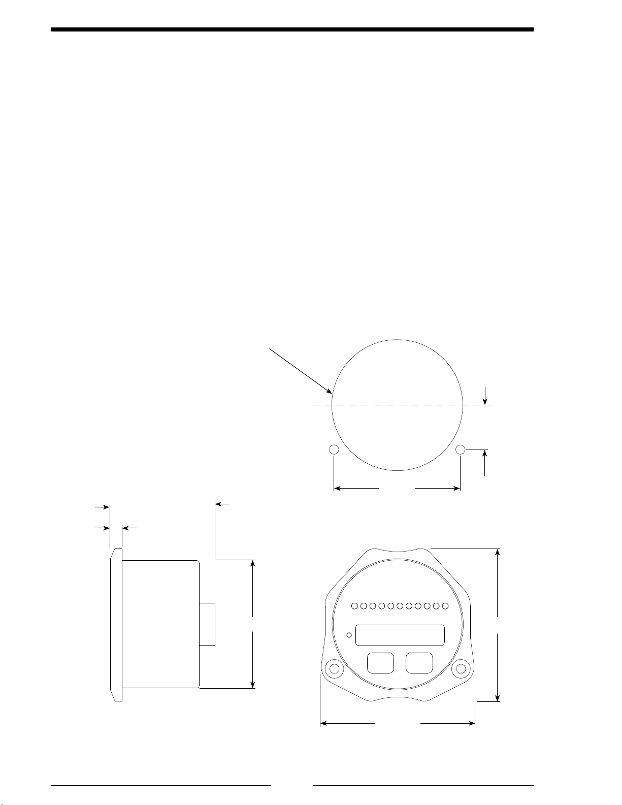
Figure 2. Display Module Mounting Dimensions ..................................................... 6
Figure 3. Pressure Sensor Dimensions....................................................................... 7
Figure 4. Display Module Wiring ............................................................................ 16
Figure 5. Pressure Sensor Wiring............................................................................. 17
Figure 6. AMA210 Wiring....................................................................................... 18

AMA200 Rev150720
3
INTRODUCTION
Overview
The Breathing Air Monitoring System is designed for use on aerial devices. It has
11 LEDs that indicate the percentage of air in the bottle. When the air in the bottle
drops below the low air setting, the LEDs ash. A 5-digit LED display shows the actual
bottle pressure.
Features
Audible and Visual Alarm for Low Air Warning
Programmable for Different Size Air Bottles
Shows Pressure and Percent of Air in the Bottle
Displays Air Pressure in PSI, kPa, or Bar
Multiple Remote Displays
LED Display Brightness Automatically Adjusts for Day/Night Viewing
Specications
Control Module
Supply Power: 9 to 30 VDC
Supply Current: 1.5 Amps Maximum
Dimensions: 3 1/4" Wide by 3 1/4" High
Unit of Measure: PSI (Program Option for kPa, Bar)
Pressure Sensor
Model Number: XE-AM2PT1
Pressure Range: 0 to 8000 PSI
Proof Pressure: 16000 PSI
Excitation Voltage: 5 VDC
Output Voltage: 0.5 to 4.75 VDC

AMA200 Rev150720
4
GENERAL DESCRIPTION
Components
The Breathing Air system consists of the following components:
Display Module
Pressure Sensor
Audible Alarm Buzzer
Cables
Display Module
The display module is waterproof and has dimensions less than 3 1/4 inches high
by 3 1/4 inches wide by 2 inches deep. All controls and indicators are located on the
front of the display module. (Refer to Controls and Indicators.)
Pressure Sensor
The pressure sensor is mounted on the air tank manifold. It provides an input signal
to the display module that is proportional to the tank pressure.
Audible Alarm Buzzer
A ground is provided at the 8-pin connector pin 6 to activate the buzzer (max
current: 300mA).
Cables
There is one cable provided with a 8-pin connector that plugs into the rear of the
display module. (Refer to Wiring Section.)

AMA200 Rev150720
5
Controls and Indicators
All controls and indicators are located on the front of the display module. The
intensity of the display and LEDs are automatically adjusted for day or night operation.
LED Bar Graph
The LED bar graph display indicates the remaining percentage of air in the bottle,
this will be proportional to the pressure sensor input. The rst two LEDs indicate 5%
and 10%, the last two LEDs indicate 90% and 95%. The other LEDs are in ten percent
increments. All LEDs are on at full tank and ash for low air warning.
Digital Display
During normal operation this 5-digit LED display indicates tank pressure. When the
MENU button is pressed it indicates the percent of air in the bottle. When the program
access mode is selected, program specic information and settings are displayed. (Refer
to Programming Section for more information.)
MENU Button
Press to show percent of air in bottle. Used when accessing program features to
change settings or parameters.
SILENCE Button
Suppresses audio alarm (does not cancel the visual alarm), also used when accessing
program features.
Figure 1. Controls and Indicators
LED Bar
Graph
Digital
Display
MENU
Button
SILENCE
Button

AMA200 Rev150720
6
INSTALLATION
Install Display Module
Display modules are interchangeable. Programming may have to be set for primary/
remote operations.
1. Measure and mark mounting location for display module panel cutout and
mounting screw holes. Make sure there is clearance behind the panel for
the display and cables before cutting holes. Refer to Figure 2 for layout and
dimensions.
2. Cut out a 2 3/4 inch diameter hole and drill four holes (clearance or tapped)
for 10-32 mounting screws.
3. Place display module in position and secure with four screws.
4. Connect the cables and wires. (Refer to Wiring Section.)
Figure 2. Display Module Mounting Dimensions
Mounting holes are
clearance or tapped
for 10-32 screws.
3 1/4"
3 1/4"
1/4"
2"
2 3/4"
2.7"
.95"
Panel Cutout
2 3/4" Diameter
C
L

AMA200 Rev150720
7
Install Pressure Sensor
The pressure sensor is mounted on the manifold of the air tank. T-ttings can be
used to mount the pressure sensor.
1. Screw the sensor into a 1/4-18 NPT hole.
Caution: Do not use the main body that houses the electronics to tighten the
pressure sensor. Damage to the sensor may occur.
2. Tighten the sensor with a 3/4 inch wrench on the lower hex tting.
3. Connect the pressure sensor cable from the display module to the pressure
sensor. (Refer to Wiring Section.)
Caution: Do not use the main
body that houses the electronics
to tighten the sensor. Damage to
the sensor may occur.
Figure 3. Pressure Sensor Dimensions
3-Pin Packard
Connector
Vent Port
3/4" HEX
Pressure Port
1/4" NPT
1.62"
3.0"
.84"

AMA200 Rev150720
8
Install Buzzer
Install the buzzer close to the display module so the audible warning is easily
associated with the visual warning on the display.
The optional buzzer provided by FRC requires a cutout hole of 1-1/8" (1.125").
Pin 6 on the 8-pin connector at the rear of the control module is provided to connect
the optional buzzer. Connect the ground side of the buzzer to pin 6. (Maximum current
through pin 6 is 300 mA.) (Refer to the Wiring Section.)

AMA200 Rev150720
9
OPERATION
On power-up the Breathing Air system is in the normal operating mode. Information
from the pressure sensor or from the datalink interface is processed and displayed.
Operator input is necessary only when accessing program information.
The digital display indicates bottle pressure above 500 PSI in increments of 10.
(If the display module is programmed for the units of measure to be Bar, it shows one
digit to the right of the decimal point.)
The bar graph display shows the percentage of air in the bottle in ten percent
increments. Press the MENU button to display the actual percent of air left in the bottle.
Low Air Warning
The Low Air warning triggers when the air in the bottle drops below the low air
warning setting (refer to Programming Section code 316). Both audible and visual
alarms are generated. Pressing the SILENCE button suppress the audible alarm. The
visual alarm includes the bar graph ashing and LoAir warning message showing in
the display. To clear the visual alarm the air pressure must rise at least 30 PSI above
the low air warning set point.
On power-up with the bottle pressure less than 5% full, the audio alarm is disabled.
If the pressure is between 5% and the low air warning pressure setting the alarm sounds
one time for ten seconds.
Program Information
Pressing the MENU button allows the operator to see the exact percent of air
remaining in the bottle.
Datalink Interface
The datalink interface provides a way of connecting multiple display modules on
a shared data bus. The correct ID number must be programmed for each module (see
Program Code Descriptions).
Primary Display Module
Primary display modules receive input from the pressure sensor. At power up all
programming information is sent to all remote displays on the datalink. An E212 error
code shows if the pressure sensor input is out of range.
Remote Display Module
Remote display modules receive all information from the primary display via the
datalink. An E201 error code shows if the datalink input is missing.

AMA200 Rev150720
10
Test Mode
The test mode is used to test all LEDs, alarm outputs, and communication links
between primary and remote display modules. The test mode will not activate when
there is a low pressure warning.
1. Press and hold the SILENCE button.
Result: The audible alarm sounds.
Result: The LED bar graph cycles showing empty (one LED on) and then full
(all LEDs on).
Results: The display cycles showing tESt and then 8888.
2. Release the SILENCE button.
Result: The display module returns to normal operation.

AMA200 Rev150720
11
PROGRAMMING
The program access mode is selected and inputs are made using the two pushbutton
switches on the front of the display module. The digital display shows stored data and
operator inputs. (Refer to Figure 1.)
Note: When entering codes in the program access mode there is a time-out
feature that requires an operator input every three seconds. If an input is
not detected within ve seconds the program returns to normal operation.
Inputs
The two pushbutton switches on the front of the display module allows the operator
access to stored data and program functions.
The MENU button is used to display the percent of air remaining in the tank.
Both the MENU and SILENCE buttons are used to enter program codes.
Once a program code is entered, the MENU button selects the digit to change and
the SILENCE button changes the digit or option choice.

AMA200 Rev150720
12
Program Access Mode
To gain access to the program features a three-digit program code must be entered.
Review the Program Code Descriptions or refer to Table 1. Program Code Quick
Reference for the proper three-digit code.
Note: There is a time-out feature that returns the program to normal operation
in ve seconds if input is not detected.
Select Program Access Mode
Turn on power. Press the MENU button and hold it until the display shows ve
dashes. The program is ready for a three-digit program code to be entered.
Enter Program Code
Note: There is a time-out feature that returns the program to normal operation
in ve seconds if input is not detected.
1. Select the Program Access Mode (ve dashes are shown in the display).
2. Press the MENU button. The number 100 shows in the display with the rst
digit (1) ashing. Each time the MENU button is pressed the number increments
by 1. Set the rst digit to the desired number.
3. Press the SILENCE button. The second digit ashes. Each time the SILENCE
button is pressed the number increments by 1. Set the second digit to the desired
number.
4. Press the MENU button. The third digit ashes. Each time the MENU button is
pressed the number increments by 1. Set the third digit to the desired number.
When a valid three-digit program code is entered, a program value or an option
shows in the display. If an invalid code is entered an error code shows in the display.
Note: When a valid code has been entered and a program value or an option
shows in the display, the time-out feature is disabled.
Change Values or Options
Press the MENU button to select the digit to be changed. The digit ashes. Press
the SILENCE button to change the digit or the option choice.
Exit Program Access Mode
Press both the MENU and SILENCE buttons and hold them until the display
shows ve dashes. Release the buttons and enter a new code or after ve seconds the
program times out and returns to normal operation.

AMA200 Rev150720
13
CODE FEATURE OPTION
312 ID Number 0 to 99
313 Module Function Pri, SLA
314 Unit of Measure/
Full Bottle Pressure
PSI, kPa, BAR
0 to 8000
316 Low Air Warning 20 to 99 (%)
330 Audible Alarm 00 to 99
340 CAN Terminator On, Off
E201 Datalink Failure Check Datalink and Programming
E202 Invalid Program Code Entered Re-Enter Code
E208 Memory Failure Contact Factory
E212 Pressure Sensor Voltage Out of Range
Table 1. Program Code Quick Reference
Notes:
- Refer to Program Code Descriptions for detailed information.
- The time-out feature returns the program to normal operation in ve
seconds if input is not detected.
- When a valid code has been entered and a programed value or option is
shown in the display, the time-out feature is disabled.

AMA200 Rev150720
14
Program Code Descriptions
When a valid three-digit program code has been entered, a program value or option
shows in the display. The MENU and SILENCE buttons are used change the data.
Press the MENU button to select the digit to be change. The digit ashes. Press
the SILENCE button to change the digit or the option choice.
Code 312 ID Number
Factory programmed value: Id 0
Options: 0 to 99
This code sets the datalink identication (ID) number for the display module. The
display is programmed with an ID number between 0 and 99. When a display module
is programmed with Id 0 no data is output to the datalink. The ID number assigned to
a remote display must match the ID number of the primary display.
Code 313 Module Function
Factory programmed value: Pri
Options: Pri, SLA
This code sets the datalink function of the display module. Two program choices
are available. Pri (primary) sets the module as a primary display. The display module
must be programmed as primary to interpret ow sensor information. SLA (slaved)
sets the module as a remote display.
Code 314 Unit of Measure/Full Bottle Pressure
Factory programmed value: PSI/4600
Options: PSI, kPa, Bar/0 - 9999
This code sets the unit of measure and sets the full bottle pressure along with the
LED display for 100%.
Code 316 Low Air Warning
Factory programmed value: 25%
Options: 20 to 99%
This code sets the low air warning. When the percent of air in the bottle is below the
low air warning programmed value, both audible and visual alarms will be generated.
Code 330 Audible Alarm
Factory programmed value: 0

AMA200 Rev150720
15
Options: 00 - 99
This code sets the time interval (1 to 99 minutes) after the silence button is pressed
until the audible alarm sounds again. If set to 0, the alarm will not repeat after the
silence button is pressed.
Code 340 CAN Terminator
Factory programmed value: On
Options: On, Off
This code sets the datalink terminating resistors for this module.
Error Code E201 Datalink
The remote does not detect a valid packet on the datalink from the primary.
Error Code E202 Invalid Code
An invalid program code has been entered. Re-enter program code when the digital
display resets.
Error Code E208 Memory
There is a failure with the internal memory of the module. The bottle pressure shows
in the display alternating with the error code. The Low Air Warning, LED bar graph,
and programming does not function. Contact factory if this error code is displayed.
Error Code E212 Sensor
The primary does not detect the pressure sensor, or the output voltage from the
sensor is out of range (0.3 to 4.9).
Exit Program Access Mode
Press both the MENU and SILENCE buttons and hold them until the display
shows ve dashes. Release the buttons and enter a new code, or after ve seconds the
program times out and returns to normal operation.

AMA200 Rev150720
16
WIRING
The following gures include wiring and cable information.
Display Module
A remote display module requires four (4) wires, power (pins 1 and 2) and the
datalink connection (pins 7 and 8) to the primary display. A remote display must be
programmed with the same ID number as the primary display.
Figure 4. Display Module Wiring
8-Pin Connector/Cable
Pin Description
1 Power
2 Ground
3 Pressure Sensor +5 VDC
4 Pressure Sensor Ground
5 Pressure Sensor Signal
6 Buzzer Ground (300ma)
7 Proprietary Datalink (–)
8 Proprietary Datalink (+)
Rear View
Pin 1

AMA200 Rev150720
17
Pressure Sensor
Figure 5. Pressure Sensor Wiring
Signal
Output
Supply
Voltage
Ground Sensor Cable from
8-Pin Connector
Pressure Sensor
(Side View)
Pressure Sensor
(Top View)
Vent
Port

AMA200 Rev150720
18
Figure 6. AMA210 Wiring
AMA210
The AMA210 kit includes a 8-pin connector with butt crimps. When the pressure
sensor kit is ordered separate it has a connector with three wires that needs to be
connected to the display module.
Butt
Connectors
+ VDC
GND
RED
BLK
ORG
WHT
GRN
YEL
BLU
BRN
8-Pin
Deutsch
Connector
8-Pin Connector Wiring
Pin Wire Color Description
1 Red Power
2 Black Ground
3 Orange Pressure Sensor +5 VDC
4 White Pressure Sensor Ground
5 Green Pressure Sensor Signal
6 Yellow Buzzer Ground (300ma)
7 Blue Proprietary Datalink (–)
8 Brown Proprietary Datalink (+)
GRN
BLK
RED
Pressure Sensor Wiring
3-Pin Connector
Pin/Wire Description
A/Black Ground
B/Red Supply Voltage
C/Green Signal Pressure Sensor
Connector

AMA200 Rev150720
19
NOTES

AMA200 Rev150720
20
Table of contents
Other FRC Measuring Instrument manuals

FRC
FRC DATATRON FTC200 User manual

FRC
FRC Insight Ultimate Series User manual

FRC
FRC FPA400 User manual

FRC
FRC SeatMonitor SBA1GD User manual

FRC
FRC Insight Series User manual

FRC
FRC DFA400 User manual

FRC
FRC InView 360 HD AVM User manual

FRC
FRC FPA400 User manual

FRC
FRC ThrottleXcel ELA100 User manual

FRC
FRC ThrottleXcel ELA100 User manual
Popular Measuring Instrument manuals by other brands

Status Instruments
Status Instruments DM4000U manual

B.E.G. LUXOMAT
B.E.G. LUXOMAT KNX WTS-GPS Installation and operating instruction

Nippon
Nippon MA-3 Solo Service manual

PCE Instruments
PCE Instruments PCE-WB 20SD manual

SIGLENT TECHNOLOGIES CO.,LTD
SIGLENT TECHNOLOGIES CO.,LTD SSA3000X Series user manual

Ascentac
Ascentac OLM300 user guide