9 10
B.- Cleaning and maintenance
Duetotheunfavourableconditions(swarth,coolants,highpressure,etc.)withwhichthese
viceshavetoworkinsidethemachiningcentres,itisimportantthattheviceiscleanedregularily.
Asimplecleaningoperationisusuallysucientbyusingthesidevents.
Werecommendasuctionpumpsystemasopposedtocompressedairwhichcouldcause
injury.Acompletecleaningoperationshouldbecarriedoutevery1000workinghours.Todoso,
the4ange-clampscrews(4026-090;4051-125)mustbeloosened,thecentraljawremoved,
andtheassemblyofthe2boltsandthespindlewiththeprotectorplatestakenoutofthevicebody
takingcaretoavoidtheboltsfromrotatinginthespindle.
Thenextstepistocleanthevicebodyandtheswarthinthespindlesandintheinteriorof
bothbolts.
Werecommendthatallslidingsurfacesshouldbegreased.
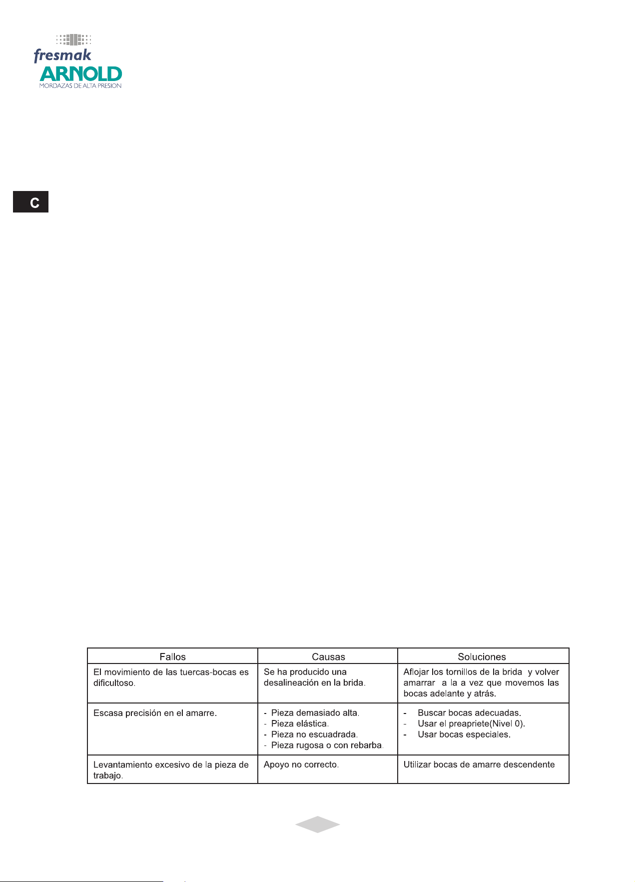
C.- Instructions for Changing and Replacing the Spindles
1) Loosenthecentralxedjaw(4106) or (4131),bodydowelpins(4122-090;9111-125)andthe
4angescrews.Thentakeoutthewholeassembly(bolts,spindlesandsidejaws).
2) UnscrewtheAllensetscrew(0004)anddetachtheange-regulatorassemblyfromthehy-
draulicunit.Themainspindle(4009)hastwoatsurfacesoneitherendtosimplifythisope-
ration.Thebolt(4007)isnowunscrewedfromthemainspindle.
3) Toreleasetheotherbolt(4102),unscrewthesetscrew(0215)locatedonthenutofthepiston
(4035)andthenunscrewthispiston.Thiswayonecantakeoutthenut(5-090;3-125)andthe
mainrightspindle(4102)loosennut(4003).
4) Ifthespindlerotateswhentakenout,thenutsmayhavecomeo-centre.Whenthisoccurs
thenutsmustbecentredbeforesettingthejaws.
D.- Disassembling the Hydraulic Unit
1) Loosenthesetscrew(0215)locatedinthecylinder(4004),unscrewthemainspindle(4009)
thusdetachingitfromthecylinder.
2) Removethebellevillesprings(0213-090;0007-125),andtakeoutthesmallpiston(4029-090;
0012-125).
3) Removethecylinder(4004),thelargepiston(4034),thewasher(4005),andthesmalland
largeseals.Withthe125modelremovethecover(4037)andtheseal(0011).
E.- Hydraulic Oil Relling
1) Placethesmallseal(0009)facingupinitssettinginthecylinder.Thenintroducethecylinder
(4005)washerdownintheoppositedirection.
2) Theseal(4006-090;0011-125)andcap(4037)(The090modelhasnocap)areattachedto
thepistonwhichisthenintroducedintothecylinder.Inordertoasurethecorrectpositionof
theseals,onemustblowairfromoneoftheendsofthepiston.
3) Placingtheassemblyinaverticalposition,thepistonisthenlledwithhydraulicoiltomaxi-
mumcapacitymakingsurethatthereisnoairtrappedintheoil.Thiscanbedonebystiringa
thinrodandthusremovinganyvisiblebubbles.
4) Werecommendhydraulicoilwitha6,5E/50ºviscosity(forexample,RenolinMR20–Fuchs).
5) Thesmallpiston(4029-090;0012-125)isslowlyintroducedintothelargepiston(4034),sea-
lingthechamber.Thepistonmustbeperfectlycleansoasnottodamagetheinterior.
6) Holding the main spindle (4009), introduce the belleville springs (0213-090; 0007-125).
Threadthedeposit(4004)tothespindleuntilthespringsarecompressed.Thehydraulicunit
isnowassembled.
7) Introducethepiston(4028)insidethespindle(4009).
8) Threadthemainspindleintheangeassembly.