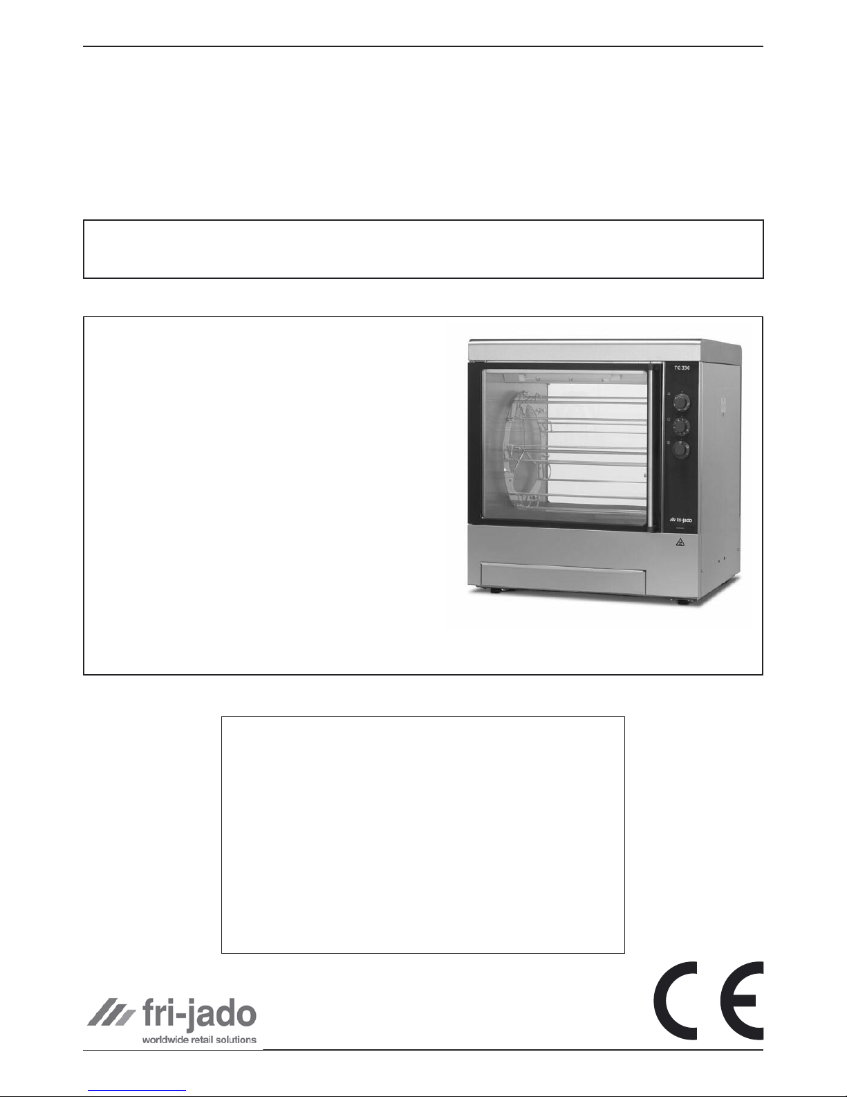
Page 5 of 10
INSTALLATION OF THE TG110h/330h/550h
Installation Manual TG 110h/330h/550h form 9123657 rev. 11/2005
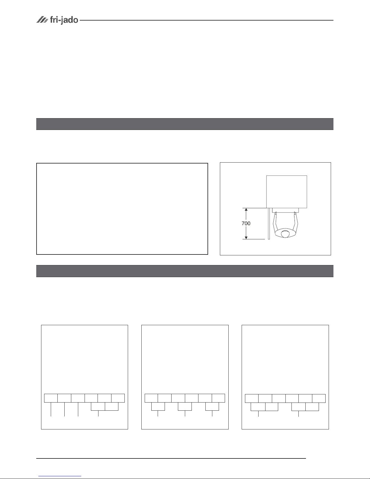
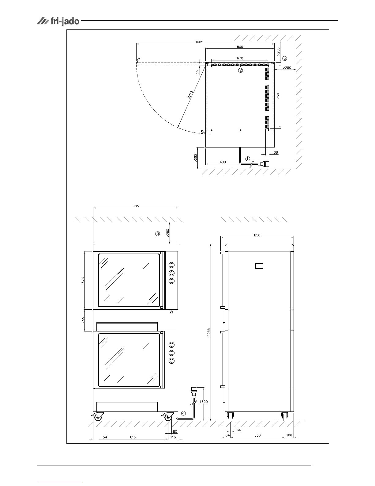
IMPORTANT: Make sure you leave
sufficient space around the rotisserie
or warmer to easily remove or insert
the rotor. If the base has (rotating)
wheels, the floor on which it rests
must be level.
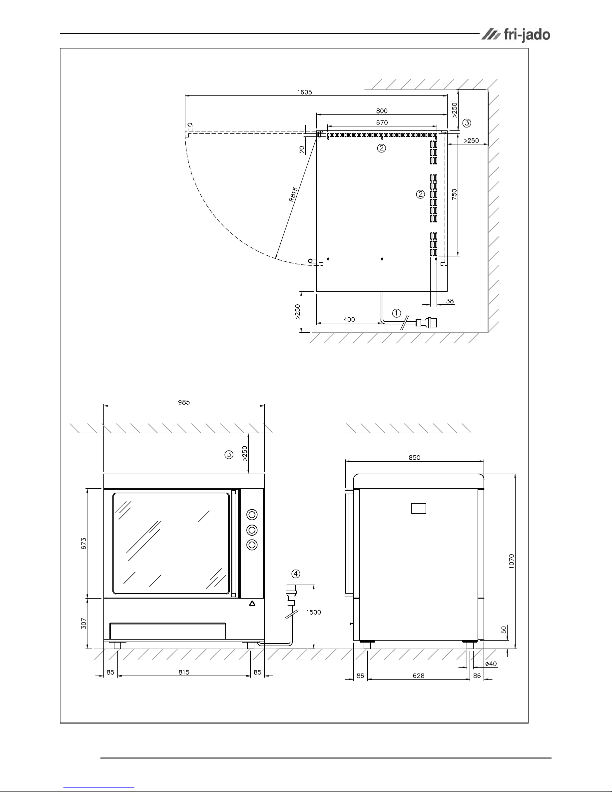
INSTALLATION
LOCATION
Immediately after unpacking the oven, check for possible shipping damage. If the oven is found to
be damaged, save the packaging material and contact the carrier within 15 days of delivery.
Prior to installation, test the electrical service to assure that it agrees with the specifications on the
machine data plate located on the right side panel near the controls.
The oven must be installed on a level surface. The installation location must allow adequate clea-
rances for servicing and proper operation.
The connecting cable for the unit must be equipped with an approved plug connection. If use is to
be made of a permanent connection, the connecting cable must be connected to a manual on/off
switch that is installed near the unit in a clear visible manner.
INSTALLATION
For a single-phase 200 V or 230 V ~
circuit with neutral, the unit must be con-
nected according to the figure below.
For a 3-phase 400 V ~ circuit with neu-
tral, the unit must be connected according
to the figure below.
400 V, 3N ~ 50...60 Hz 200 V or 230 V, 1N ~ 50...60 Hz
1 2 3 4 5 6
N
L1
1 2 3 4 5 6
L2L1 L3
For a 3-phase 200 V or 230 V ~ circuit
without neutral, the unit must be connec-
ted according to the figure below.
200 V or 230 V, 3 ~ 50...60 Hz
N
1 2 3 4 5 6
L2L1 L3