Friax Genesis & Vintage SPC EVPL User manual

Notice technique d'installation
Installation manual
Installationsanleitung
SPC EVPL
Genesis & Vintage
Les caractéristiques données dans cette fiche technique peuvent évoluer sans avis préalable,
avec les améliorations que "FRIAX Industrie" entend toujours apporter à sa production.
"FRIAX industrie", in a constant endeavour to improve its products reserves the right to change
any information contained in this leaflet without prior warning
Im ständigen Bemühen um Produktverbesserungen behält sich "FRIAX Industrie" das Recht vor,
die technischen Angaben auf diesem Datenblatt jederzeit ohne Vorankündigung zu ändern..
EU-NT-SPCEVPL-RSF-0321
A partir du N°série 20FR-TC-16800

2
Présentations Presentations
Merci d’avoir choisi un split système Friax pour la cave pour contrôler le vieillissement de vos vins.
Prenez le temps de lire ce manuel d’utilisation. Il vous permettra de comprendre et de maîtriser les opérations pour
installer et régler les appareils de la gamme SPC.
Qu’est ce qu’un split système Friax pour la cave ?
La gamme SPC est un système de réfrigération spécialement dimensionné pour maintenir la température et
l’hygrométrie optimale au bon vieillissement de vos vins. Le système se compose de trois éléments essentiels que sont
l’évaporateur, le groupe de condensation et le régulateur. Ces éléments sont réunis entre eux par une liaison frigorique
et une liaison électrique.
Thank you for choosing a split FRIAX system to control the aging of your wine.
Take the time to read this manual. It will help you understand the steps to install and adjust the equipment SPC range.
What is a cellar split system FRIAX?
The SPC series is a refrigeration system specially designed to maintain the optimum temperature and humidity at the
right age of your wines. The system is composed of three essential elements which are the evaporator, the condenser
unit and the regulation box. These elements are interconnected by a refrigerant pipe and an electrical connection.
Danke für die Wahl eines geteilten FRIAX System, um die Alterung der Wein steuern.
Nehmen Sie sich Zeit zum Lesen dieses Handbuchs. Es wird Ihnen helfen, die Schritte zur Installation und Anpassung
der Ausrüstung SPC Bereich.
Was ist ein Split-System ceilar FRIAX?
Die SPC-Serie ist eine Kälteanlage speziell bemessen, um die optimale Temperatur und Luftfeuchtigkeit im richtigen
Alter Ihrer Weine zu erhalten. Das System besteht aus drei wesentlichen Elemente Welches sind die Verdampfer,
Kondensator-Einheit und die Steuereinheit. Diese Elemente werden durch eine Kältemittelleitung und eine elektrische
Verbindung miteinander verbunden sind.
Equipements Accesories
A la réception, vous devez trouver dans votre colis les composants suivants:
At the delevery, you must nd in your package the followings items:
An der Rezepon, müssen Sie in Ihrem Paket die folgenden Komponenten zu finden :
-une télécommande sans l / Wireless controler / eine Funk-Fernbedienung
-un boitier de régulation / control bo / kontrollkästchenx
-une sonde dans son boîtier /a probe in its case / ein Sonde in ihrem Gehäuse
-un câble droit RJ de classe 6 d’une longueur de 5 m / 5m of class 6 RJ patch cord
/ eine Klasse 6 RJ-Patchkabel mit einer Länge von 5 m
-une unité intérieur / an indoor unit / eine Inneneinheit
-une unité extérieur / an outdoor unit / eine Außeneinheit
-un support groupe avec vis et plot anti vibration / a group support with screws and anti vibration pad
ou
or
order
Les kits présentés dans ce document ne cont pas fournis. / The kits presented in this document are not provided. /
Die in diesem Dokument enthaltenen Kits werden nicht geliefert

3
Ce symbole indique que le manuel d’installation doit être lu attentivement.
This symbol indicates that the installation manual should be read carefully.
Ce symbole indique qu’un technicien de service doit manipuler cet équipement en
se référant au manuel d’installation.
This symbol indicates that a service technician should handle this equipment in
referring to the installation manual.
Ce symbole indique que des informations sont disponibles, telles que le manuel
d'utilisation ou le manuel d'installation.
This symbol indicates that information is available, such as the manual
operating instructions or installation manual.
Avertissement Warning
LISEZ ATTENTIVEMENT LE MANUEL AVANT D’UTILISER L’APPAREIL
et conservez-le pour y référer ultérieurement
Une installation ou utilisation incorrecte, peuvent entraîner des blessures aux personnes, des
dommages aux biens, et l’annulation de la garantie constructeur. Le non-respect des consignes
de sécurité et des normes locales en vigueur lors de l’installation ou utilisation décharge le
fabricant de toute responsabilité.
Improper installation or use can result in injury to persons,
damage to property, and cancellation of the manufacturer's warranty. Failure to follow instructions
safety and local standards in force during installation or use discharges the
manufacturer of any responsibility.
Veillez à installer l’appareil dans un endroit à l’abris des intempéries et hors gel.
Make sure to install the device in a place protected from bad weather and frost.
- Sachez que certains gaz réfrigérants peuvent être inodores.
- Toute intervention sur un circuit frigorique doit être réaliser par un professionnel autorisé
par un organisme accrédité certiant la compétence à manipuler les uides réfrigérants.
- Be aware that some refrigerant gases can be odorless.
- Any intervention on a refrigeration circuit must be carried out by an authorized professional.
by an accredited body certifying the competence to handle refrigerant uids.
- L’appareil doit être en permanence libre de toute obstruction pour en assurer le bon
fonctionnement et réduire les risques en matière de sécurité.
- Ne perforez aucun composant du circuit réfrigérant.
- Faites preuve de prudence lors de la manipulation de l’équipement pour éviter tout dysfonctionnement.
- The device must be free of any obstruction at all times to ensure good
operation and reduce safety risks.
- Do not puncture any component of the refrigerant circuit.
- Use caution when handling equipment to avoid malfunction.

4
- L’appareil doit-être installé conformément aux réglementations locales en matière de câblage.
- Assurez-vous que les caractéristiques de l’appareil sont compatibles avec celles de l’installation électrique.
- Assurez-vous que la prise secteur est raccordée à la terre.
- N’utilisez par l’appareil s’il est endommagé
- Ne branchez l’alimentation électrique qu’une fois toute l’installation achevée.
- Eteignez toujours l’appareil et débranchez-le du secteur pour le nettoyage et la maintenance.
- Ne mettez pas vos mains ou d’objets dans les entrées et sorties d’air.
- N’essayez pas de réparer vous-même l’appareil.
- Toute utilisation et/ou modication non agréée par le fabricant peut s’avérer dangereuse pour votre
sécurité et votre santé.
- Cet appareil ne doit pas être utilisé par des enfants.
- L’utilisateur doit comprendre et être conscient des danger potentiels liées à l’utilisation de l’appareil.
- N’utilisez que les moyens et/ou outils recommandés par le fabricant pour le dégivrage ou le nettoyage.
- The device must be installed in accordance with local wiring regulations.
- Make sure that the characteristics of the device are compatible with those of the electrical installation.
- Make sure that the mains socket is connected to earth.
- Do not use the device if it is damaged
- Do not connect the power supply until the entire installation is complete.
- Always switch o the appliance and unplug it from the mains for cleaning and maintenance.
- Do not put your hands or objects in the air inlets and outlets.
- Do not try to repair the device yourself.
- Any use and / or modication not approved by the manufacturer may be dangerous for your
safety and health.
- This appliance must not be used by children.
- The user must understand and be aware of the potential dangers associated with the use of the device.
- Use only the means and / or tools recommended by the manufacturer for defrosting or cleaning.

Split systems SPC
Unité intérieur / Indoor unit SPC… 30 48 82 122 170 230
1 x 200 2 x 200 2 x 200 2 x 200 3 x 200 4 x 200
m3/h 590 650 580 870 1160
A max
Ø3/8" 3/8" 3/8" 1/2" 5/8" 5/8"
Ø1/4" 1/4" 1/4" 1/4" 3/8" 3/8"
kg 11.5 13 12.5 13.5 18 23
RAL7024
Anthracite
Raccordements gaz / gas connections /
Anschlüsse (Flare)
aspiration / suction /
Sauggasleistung
liquide / liquid line /
flüssigkeitleistung
Couleur carrosserie / body color / Farbe
ø Ventilateur / ø fans / ø lüfter
Débit d'air / airflow / luftmenge
Poids net /net weight / Gewicht
Intensité max évaporateur / current / Nennstrom
T cave= +12°C - Text= 32°C
A max
Genesis
Vintage
0.3 0.6 0.6 0.6 1 1.2
3.9 4.1 4.3 5 8 10
280
5
3500
230 V/1+T
1700
10 / 8.2
51
48
47
5/8"
3/8"
2100
20
63
RAL7035
2000
SPC… 30 48 82 122 170
W780 1100 1550 2200 2900
W
Unité extérieur / Outdoor unit SPC… 30 48 82 122 170
50Hz 230 V1+T 230 V/1+T 230 V/1+T 230 V/1+T 230 V/1+T
m3/h 225 335 1130 980 1700
A 3.3 / 2.4 4.2 / 3.3 4.6 / 3.7 6 / 4.6 8 / 6.4
Standard db 40 44 44 44 51
avec BNS db 37 41 41 41 48
W db 37 40 40 40 47
Ø3/8" 3/8" 3/8" 1/2" 5/8"
Ø1/4" 1/4" 1/4" 1/4" 3/8"
g500 600 1260 1450 2000
m20 20 20 20 20
Ø
2 x 1/2" M 2 x 1/2" M 2 x 1/2" M 2 x 1/2" M 2 x 1/2" M 2 x 1/2" M
kg 36 38 54 57 63
RAL7035 RAL7035 RAL7035 RAL7035 RAL7035
Tension / voltage / spannung
+32°C EXT
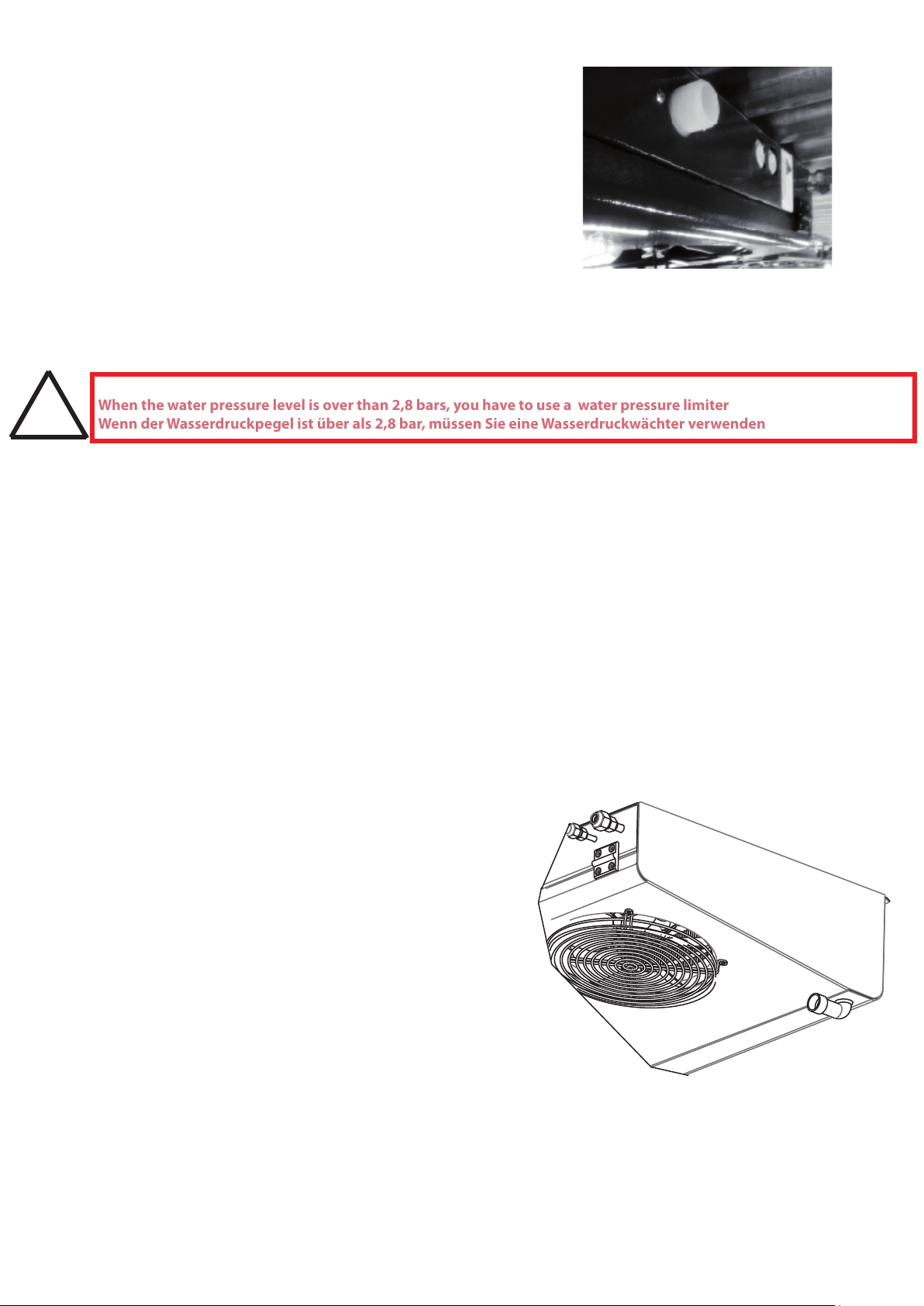
Raccordement eau W / water connections for W / WasseranschluB W
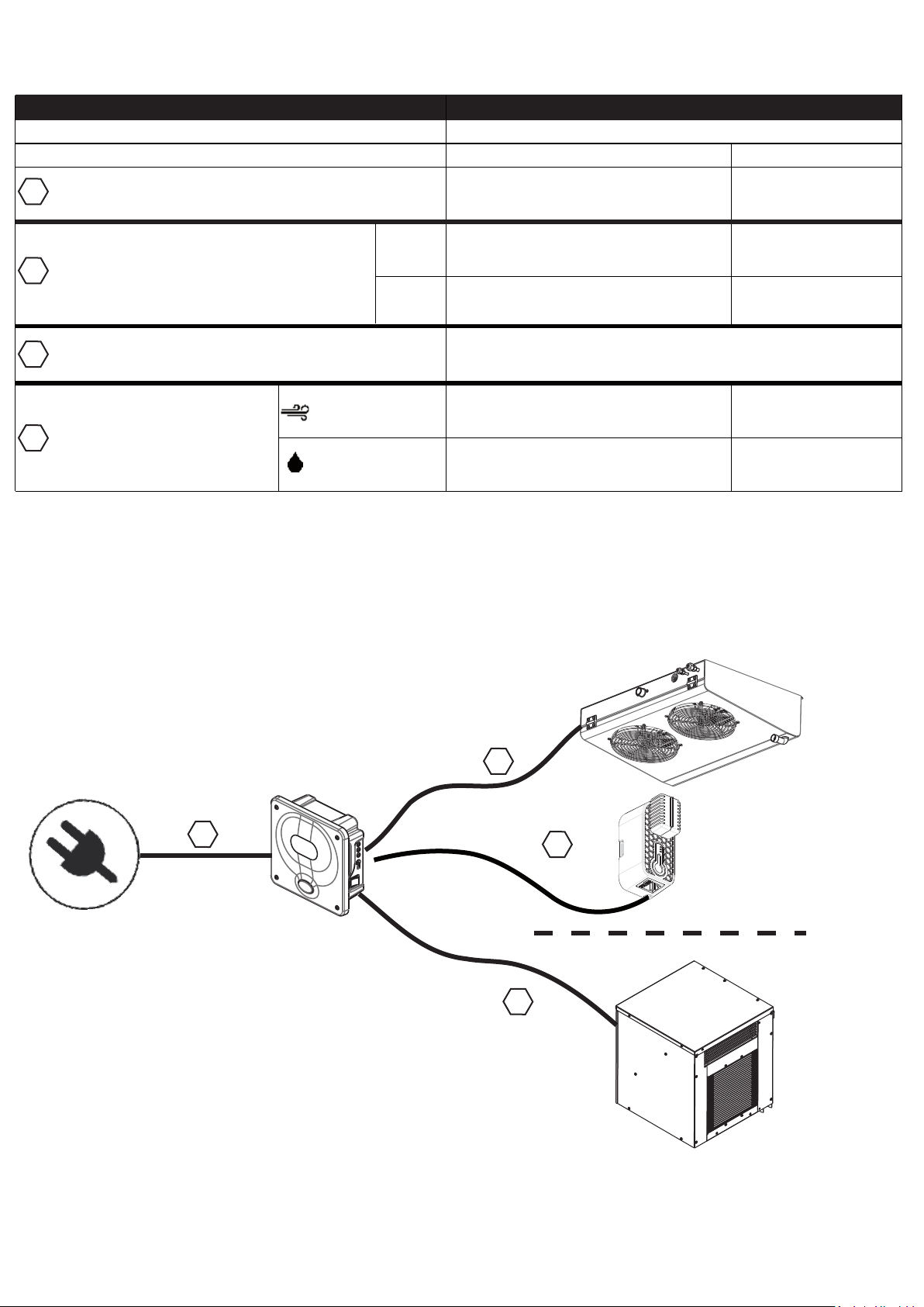
Distance max groupe-évap / maxi distance condensing unit
-evaporator /max. Leitungslange zw Aggretat u.Verdampfer
Raccordements gaz / gas connections /
Anschlüsse (flare)
Débit d'air / air flow / luftmenge
Intensité absorbée groupe AIR / EAU / Current / Nennstrom
Poids net /net weight / Gewicht
Couleur carrosserie / body color / Farbe
Puissance chauffage / heating capacity / Heizleistung elektrisch
Puissance frigorifique / Cooling capacity / Kühleistung
aspiration / suction /
Sauggasleistung
liquide / liquid line /
flüssigkeitleistung
Précharge pour 6m de liaison/ Precharge to 6m/ Gasfüllung für 6 m
Si plus ajouter 20g/m / If more add 20g/m / Add 20gr/m mehr
Niveau de pression sonore à 5m / sound pressure level
at 5m / Schalldruckpegel in 5m Abstand
850 850 850 1000 1600
R452AR134A
Puissance absorbé en chaud / Absorbed power in hot
Energieaufnahme in heißem
Puissance absorbé en froid / Absorbed power in cold
Energieaufnahme bei Kälte
W
W
538
900
719
938
1009
938
1307
1088
1743
1777
230
230
2215
2291
SPLIT SYSTEM A CONDENSATION A AIR OU A EAU
SPLIT SYSTEM WITH AIR OR WATER COOLED CONDENSOR
SPLIT-SYSTEM LUFT ODER WASSERHÜHLUNG
Données techniques Technical data - Technischedaten
RAL7024
Anthracite
RAL7024
Anthracite
RAL7024
Anthracite
RAL7024
Anthracite
RAL7024
Anthracite
Efficience énergétique / Energy efficiency / Energieeffizienz / C.O.P W2.1 2.15 1.73 1.69 1.8 1.68
Amax
Intensité Max groupe AIR / EAU / Current / Nennstrom
15.2 / 15.15.1/ 4.2 6 / 5.1 7.2 / 6.8 9.2 / 8.1 13.6 / 12.8

30 48 82 122 170 230
V / Hz 230 / 50
Protection / Absicherung A10 16 20
3G1,5
3G1,5
5G1,5 + 2 x 0.5 mm²
Fourni : Câble droit RJ de classe 6 (lg 5m maxi)
Provided : Class 6 patch cord RJ (length 5m)
Sonde ambiante - Boîtier de contrôle
Ambient probe - contrôl box / Umgebungssonde - Kontrollbox
Unité intérieure - Boîtier de contrôle
Indoor unit - Control box
Innengerät - Schaltkasten
Unité extérieur - Boîtier de contrôle
Outdoor Unit - Control Box
Außengerät - Kontrollbox
3G1,5
6
Liaisons électriques Electrical connections - Elektrische Verbindungen
Raccordements électrique / Electrical connection / Stromanschluss
Alimentation / Power Supply / Stromversorgung
Secteur - Boîtier de contrôle
Sector - Control Box / Sektor - Kontrollbox
Genesis
Vintage
5G1,5
Condensation à air
Air condensation
Luftkondensation
Condensation à eau
Water condensation
Wasserkondensation
230 v 50 hz
Schéma de principe Schematic diagram - Schematische Darstellung
12°C
32°C
1
2
3
4
1
2
3
4
3G2,5
6G2,5
4G2,5 + 2 x 0.5mm²
3G2,5
4G1,5

=
596
=
20851
3
12
Ø 8
1
2
1174
2
493
==
20851
3
12
Ø 8
1
493
SPC 170 Genesis, Vintage
SPC 82-122 Genesis, Vintage
SPC 230 Genesis, Vintage
1540
2
658
==
20851
3
12
Ø 8
1
658
210
Ø 1" G
440
200
Ø 20
210
Ø 1" G
440
200
210
Ø 1" G
440
200
790
SPC 30 Genesis, Vintage
SPC 48 Genesis, Vintage
200
Les accessoires (vis, chevilles, rondelles) nécessaires à la mise en place de l’évaporateur ne sont pas fournis.
Accessories (screws, bolts, washers) required for the implementation of the evaporator are not provided.
Zubehör (Schrauben, Bolzen, Unterlegscheiben) für die Implementierung des Verdampfers erforderlich sind, nicht vorgesehen.
151
441
29
29
200
151
441
29
29
50647
200
52
ø9
50647
200
52
ø9
Ø 20
300
600
300
600
7
1.1 Fixation plafond Ceiling xing - Deckenbefestigung
1. Installation de l’unité intérieur
Installation of the indoor unit - Installation der Inneneinheit

8
Raccorder l’alimentaon en eau sur l’humidificateur HGR%
Raccord Electro-Vannes (20/27 mm )
Solenoïde valve connecon (20/27 mm )
Magnetvenl-Anschluss (20/27mm)
Connect the water supply to the humidifier HGR%
1.2Raccordement eau Vintage water connection - Wasseranschluss
Verbinden Sie die Wasserversorgung mit dem Lubefeuchter HGR%
En cas de pression d’eau supérieure à 2,8 bars, l’utilisation d’un kit limiteur de pression est indispensable
When the water pressure level is over than 2,8 bars, you have to use a water pressure limiter
Wenn der Wasserdruckpegel ist über als 2,8 bar, müssen Sie eine Wasserdruckwächter verwenden
!
1.3 Raccordement Kit KLP Accessoire en option
connection kit KLP Optional accessory - Verbindungssatz KLP Optionales Zubehör
(Voir Liste des Accessoires page 31 à 34)
1.4 Raccordement vidange Drain connection - Verbindung ablassen
Raccorder le tube de vidange (ø 20) à l’extrémité du coude.
Connect the drain tube (ø 20) to the end of the elbow with the supplied collar.
Verbinden Sie den Ablaufschlauch (ø 20) mit dem mitgelieferten Kragen
mit dem Ende des Ellenbogens.

9
C
G
ØH
A
D
B
E
ØF
MODEL
A
B
C
D
E
ØF
G
ØH
SPC 30
430 150
160
9
160
20
SPC 48
600
490
SPC 82
790440210596220
SPC 122
1.5 Kit de pose en mural KPM2V ou KPM82-122
Wall mounting kit - Zubehör zur Wandmontage

10
769
Avec facade gainable
( KFG-GCG)
With ducted facade
Mit Kanalfassade
Groupe seul
Group only
Nur Gruppe
300
150
250
Implantation A :
Plug & Lock (voir page 11)
A
Dégagement d’air sans obstacle A minimum 2500
Clearance of air without obstacle A minimum 2500
Luftfreiheit ohne Hindernis Mindestens 2500
!
150
109
502
489
A
488
453 488
2a. Installation de l’unité de condensation à AIR 30-48 (GCG)
Installation of the external condensing unit - Installation der externen Verüssigungseinheit
2a.1 Mise en place Setting up - Einrichten
Ø 160
Ø 160 Ø 200
Ø 200
2a.2 Fixation murale Wall xation - Wandhalterung
En fonction des contraintes d’implantation ci-dessous sélectionnez votre système de xation.
Depending on the layout constraints below select your fastening system.
Wählen Sie abhängig von den unten angegebenen Layout-Einschränkungen Ihr Befestigungssystem.
Implantation B :
si A<2500mm
Kit KS2M

2a.3 Système de xation Plug & Lock fastening system - Befestigungssystem
265
339 66
2a.4Gainable avec les kits KFG-GCG et KGR160-KR
Gainable with the KFG-GCG and KGR160-KR kit - Erreichbar mit dem KFG-GCG und KGR160-KR-Kit
(Voir Liste des Accessoires page 31 à 34)
11

SPC 82 & 122
Conseils – Advice – Beratung:
-Favoriser les endroits dégagés, à l’abri du soleil
Encourage open areas, away from sun.
Bereiche fördert oen, geschützt vor der Sonne
-Attention au bruit pour le voisinage
Take care to not disturb the neighbours
Passen Sie auf, um die Nachbarn nicht zu stören
-Surélever le groupe pour éviter les feuilles et la neige
Raise the height of the unit to avoid leaves and snow
Erhöhen der gruppe auf die Blätter und Schnee zu
vermeide
-Vérier la solidité des supports
Check the strength of supports materials
Versichern sie von der Standfestigkeit der Unterlage
BNS= 25
605
565 510
380
150 *
400 * 250 *
220 *
* minimum
SPC 170 & 230
BNS= 25
565
660
710
480
2b.1 Mise en place Setting up - Einrichten
2b.2 Encastrement housing - Gehäuse
2b.Installation de l’unité de condensation à AIR 82 à 230
Installation of the Air condensing unit - Installation der Verüssigungseinheit
12

13
!A installer hors-gel
To set in frost-protection
Raccordements eau 15/21
water connecons 15/21
Wasseranschlüsse 15/21
Venlaon compresseur
Compressor fan
Fan-Krompressor
565
605
510
BNS= 25
380
440
2c.1 Système de xation Plug & Lock fastening system - Befestigungssystem
225 58
180
180
La pose du kit Bas niveau sonore doit se faire avant la xation de l’unité extérieure.
The installation of the Low sound level kit must be done before xing the outdoor unit.
Die Installation des Low-Sound-Level-Kits muss vor der Befestigung des Außengeräts erfolgen
2c. Installation de l’unité de condensation à EAU 30 à 230
Installation of the water condensing unit - Installation wasserkondensations
Les groupes à Eau sont fait pour une installation dans un local supérieure a 0°C.
The water groups are made for installation in a room above 0°C.
Die Wassergruppen sin für die Installation in einem Raum über 0°C vorgesehen.
2c.2 kit bas niveau sonore Accessoire en option,
low noise level kit Optional accessory-Kit mit niedrigem Geräuschpegel Optionales Zubehör
(Voir Liste des Accessoires page 31 à 34)

14
Sur les conduites horizontales :
Les zones basses (pièges à huile), entre
l’évaporateur et le compresseur, doivent
être évitées. Les conduites horizontales
doivent descendre légèrement vers le
compresseur. Pour les conduites
horizontales, la vitesse d’aspiration ne
doit pas être inférieure à 4 m/s.
Sur les conduites verticales :
Si Les conduites d’aspiration verticales
sont inférieures à 2m de hauteur, elles
doivent être installées avec deux
siphons, un en bas et un au-dessus de la
conduite. Si les conduites d’aspirations
verticales sont supérieures à 2m, il
faudra ajouter en plus, un siphon tout
les 2m de hauteur.
Ne pas ajouter d'huile sauf si la longueur
du réseau de uide frigorigène dépasse
8m de dénivelé; dans ce cas, utiliser
l'huile préconisée par FRIAX Industrie.
On the horizontal conducts:
The low zones (oil’s trap), between the
evaporator and the compressor must
be avoided. The horizontal conducts
have to down slightly towards the
compressor. For the conducts, the
speed of suction mustn’t be lower than
4 m/s.
On the vertical conducts:
If the vertical conducts of suction are
lower than 2m of height, they must be
installed with two siphons, one below
and one over the conduct. If the
conducts are higher than 2m, it will be
necessary to add a siphon every 2m of
height.
Do not add oil unless the network of
refrigerant’s length exceed 8m vertical
drop; in this case, use the oil recom-
mended by FRIAX Industrie.
Auf den horizontalen Führungen:
Die niedrigen Zonen (Falle des Öls),
zwischen dem Evaporator und dem
Kompressor müssen vermieden werden.
Die horizontalen Führungen haben zu
unten ein bisschen zum Kompressor. Für
die Führungen darf die Geschwindigkeit
nicht des Saugens niedriger sein als 4 m/s.
Auf den vertikalen Führungen:
Wenn Die vertikalen Führungen des
Saugens niedriger sind als 2m von Höhe,
müssen sie mit Hebern zwei, eins unten
und eins über die Führung installiert
werden. Wenn die Führungen höher sind
als 2m, wird es notwendig sein, einen
Heber jeder 2m Höhe hinzuzufügen.
Fügen Sie Öl nicht hinzu, wenn das
Netzwerk der Länge des Kühlmittels 8m
Höhenunterschied herausragt; gebrauchen
Sie in diesem Fall das Öl empfohlen durch
das FRIAX indutrie.
!
Prendre soin de bien lire ceci avant d’installer votre matériel FRIAX si le groupe extérieur est au-dessus de
l’évaporateur
Take care of reading this before installing your FRIAX-s equipment if the condensing unit is over the evapo-
rator.
Sich darum kümmern, das gut zu lesen, bevor lhr Material FRIAX unterzubringen, wenn die äuBerliche
Gruppe über dem verdampfer ist
3. Raccordement frigorique
Refrigerating connection - Refrigerating connection
Longueur frigorique maximal préconisée
Maximum recommended cooling length
Maximale empfohlene Kühllänge
20 mètres linéaires
20 linear meters
20 laufende Meter
2m
2m
hauteur maxi
8m

15
Eectuer le raccordement à la
tuyauterie (raccords are).
Après avoir raccordé, tirer au vide la
tuyauterie et l'évaporateur par l'inter-
médiaire des raccords Schraeder
situés sur les vannes du groupe de
condensation. Vérier la tenue au
vide. Si la pression ne remonte pas,
ouvrir à fond les vannes pour laisser
passer le gaz dans toute l'installation.
Bien serrer les vannes en arrière,
remettre le bouchon, le serrer avec
un outil. Avant de mettre en route,
faire une recherche générale de fuite
avec un détecteur électronique
adapté pour le uide utilisé. Mettre
en route, attendre un instant et
vérier si la charge est correcte. S'il
manque de gaz, on voit apparaitre
des bulles dans le voyant liquide
situé vers le déshydrateur. Compléter
la charge doucement jusqu'à dispari-
tion des bulles. Bien serrer les
bouchons des raccords Schraeder à
la n de l'intervention.
Make the connection to the pipe
tting (are connections).
After connecting, pull the vacuum
piping and the evaporator through
the ttings located on the Schraeder
valves of the condensing unit. Check
the vacuum capability. If the pressure
does not rise, the valves open fully to
let the gas throughout the facility.
Tighten the valve back, replace the
cap, and tighten it with a tool. Before
setting o, make a general search of
escape with an electronic detector
suitable for used uid. Switch on,
wait a moment and see if the charge
is correct. Missing gas are emerging
bubbles in the sight glass located to
the dehydrator. Complete load
slowly until the bubbles disappear.
Tighten caps Schraeder.
Die Verbindung im Rohrnetz
ausführen (Schnittstellen are).
Nach dem Anschluss, ziehen Sie den
Vakuum-Leitungen und der Verdam-
pfer durch die Beschläge auf dem
Schrader-Ventil-Gruppe bendet
Kondensation. Überprüfen Sie die
Vakuum-Fähigkeit. Wenn der Druck
nicht ansteigt, önen die Ventile voll
auf das Gas in der gesamten Anlage
zu lassen. Ziehen Sie das Ventil
wieder, die Kappe, ziehen Sie sie mit
einem Werkzeug. Vor dem Start eine
Suche mit allgemeinen Leckage
einen elektronischen Detektor für
Fluid. Einschalten, warten Sie einen
Moment und schauen, ob die Ladung
korrekt ist. Wenn er Mangel am Gas
hat Es entstehen Blasen im Schauglas
gelegen, um die Dörrgerät. Kom-
plette langsam geladen, bis die
Blasen verschwinden. Ziehen Sie
Caps Schraeder Armaturen am Ende
der Intervention.
Die Gruppe enthält die Aufgabe in Gas
für Split und 6m Verbindung
kälteerzeugend. Darüber hinaus, einen
Objekt von 20g / M von Verbindung
vorhersehen. Die Gruppe ist für Rohr-
netze bis zu 20m dimensioniert. Es ist
besser, kein üssiges Rohrnetz
Hochdruck zu isolieren.

16
SPC Genesis & Vintage
254
242
220
230
103
182 24
4 x Ø6.2
150
52
4. Raccordement électrique
Electrical connection - Elektrischer Anschluss
Longueur MAXIMUM de liaison pour la sonde ambiante: 5 m
MAXIMUM length for connecting the ambient probe: 5 m
MAXIMALE Länge für den Anschluss der umgebungssonde: 5 m
Longueur MAXIMUM de liaison pour la sonde Condenseur : 20m
MAXIMUM length for connecting the Condenser probe: 20m
Maximale Länge für den Anschluss der Kondensatorfühler: 20m
12N 3L 451L 2L 4L
1N NLABC
Unité extérieur
Outdoor unit
Unité intérieur
Indoor unit
Unité intérieur
Indoor unit
RC
CP
CDF
EVF
HGR
KCH
L
170-230
NN
3 x 1mm²
TAC1
PWM1
GND
Cable Ethernet
droit RJ
0
1
Alimentaon
Power
Stromversorgung
230V - 50Hz
Commandes moteurs EC
EC motors controls
COND
RJ
Sonde Condenseur
Condensor Probe
Kondensatorfühler
Auxiliary
Alarms Light
NO
COM
NC
Voir page 27
See page 27
Résistance de carter
Compresseur
Venlateur condenseur
Kit humidifacteur Venlateur évaporateur
Sonde température
Résistance de chauffage
N

17
4.1 Placement de la sonde et raccordement
Placement of the probe and connection - Platzierung der Sonde und Verbindung
reprise
EVPL 30-48
Genesis & Vintage
EVPL 82-122-170-230
Genesis & Vintage
Fixer la sonde sur l’évaporateur ou sur le mur, proche de la reprise pour mesurer la température ambiante de la cave.
Le cable ne doit pas gêner à l’ouverture du capot.
Set the sensor on the evaporator or on the wall, close to the recovery to measure the ambient temperature of the
cellar. The cable must not interfere with the opening of the hood.
reprise
46 9
72
Connecteur sonde
RJ
35
46
35
La boite de la télécommande est livré avec :
- une télécommande et son support
- 2 piles LR03
- Une sonde installée dans son support fournie avec :
- vis et leurs chevilles (xation sur mur)
- bandes doubles faces (xation sur l’évaporateur
Le câble droit RJ de classe 6 d’une longueur
de 5 m est fourni avec le boitier de régulation

18
M1 M2
x2 pour SPC 48 EVPL
x2 for SPC 48 EVPL
x2 für SPC 48 EVPL
Ventilateur
Fan
Lüfter
SPC 30-48 EVPL Genesis
4.2 Raccordement électrique Condensation a air
Electrical connection Air condensation- Elektrischer Anschluss Luftkondensation
Unité extérieur
Outdoor unit
Unité intérieur
Indoor unit
Unité intérieur
Indoor unit
RC CP
CDF
EVF
HGR
KCH
L
170-230
NN
PWM1
GND
0
1
Alimentation
Power supply
Spannungsversorgung
230V - 50Hz
Commandes moteurs EC
EC motors controls
COND
RJ
Sonde Condenseur
Condensor Probe
Kondensatorfühler
Auxiliary
Alarms Light
NO
COM
NC
Voir page 29
See page 29
N
max 20m
1N 2L
1L 4L
Sonde condenseur
Condensor probe
Kondensatorsonde
3L
2N
1
4
6
RC
2 x 0.5²
CD
CD
PE
CP VT
5 G 1.5²
3G 1.5²
3G1,5²
Alimentation
Power supply
Spannungsversorgung
1 2N 3L 4 5 1N 1L 2L 4L N L A B C
BP
HP
Ventilateur
Fan
Lüfter
Compresseur
Compressor
Kompressor
Résistance carter
Crankcase resistance
Kurbelgehäuse
widerstand
Unité extérieure
Outdoor unit
Schaltkasten
Unité Intérieure
Indoor unit
Inneneinheit
Boitier de régulation
Régulation Box
Schaltkasten
TAC1
PE
!
Cable Ethernet droit RJ
RJ straight Ethernet cable
RJ gerades Ethernetkabel
max 5 m
RJ
Sonde température
Temperature sensor
Feuchtetemperatursensor
7
9
8
Variateur de Vitesse
Fan speed Controler
Lüfterdrehzahlregler
EC
B=GND
J=0-10V
R=10V
BL=TAC
BL=Blanc White weiß
R=Rouge Red rot
B=Bleu Blue blau
J=Jaune Yellow gelb
Couleur Ventilateur
EC Fan color
N°1 ou Brun
N°2 ou Noir
N°3 ou Bleu

19
TC
TS
M1 M2
HGR% KCH x2 pour SPC 48 EVPL
x2 for SPC 48 EVPL
x2 für SPC 48 EVPL
Ventilateur
Fan
Lüfter
EV
SPC 30-48 EVPL Vintage
4.3 Raccordement électrique Condensation a air
Electrical connection Air condensation- Elektrischer Anschluss Luftkondensation
Unité extérieur
Outdoor unit
Unité intérieur
Indoor unit
Unité intérieur
Indoor unit
RC CP
CDF
EVF
HGR
KCH
L
170-230
NN
PWM1
GND
0
1
Alimentation
Power supply
Spannungsversorgung
230V - 50Hz
Commandes moteurs EC
EC motors controls
COND
RJ
Sonde Condenseur
Condensor Probe
Kondensatorfühler
Auxiliary
Alarms Light
NO
COM
NC
Voir page 29
See page 29
N
max 20m
PE
1N 2L
1L 4L
2 x 0.5²5 G 1.5²
5G 1.5²
1 2N 3L 4 5 1N 1L 2L 4L N L A B C
TAC1
Unité Intérieure
Indoor unit
Inneneinheit
Boitier de régulation
Régulation Box
Schaltkasten
3G1,5²
!
Cable Ethernet droit RJ
RJ straight Ethernet cable
RJ gerades Ethernetkabel
max 5 m
RJ
Sonde température
Temperature sensor
Feuchtetemperatursensor
Sonde condenseur
Condensor probe
Kondensatorsonde
3L
2N
1
4
6
CD
CD
PE
Unité extérieure
Outdoor unit
Schaltkasten
7
9
8
Alimentation
Power supply
Spannungsversorgung
BL=Blanc White weiß
R=Rouge Red rot
B=Bleu Blue blau
J=Jaune Yellow gelb
Couleur Ventilateur
EC Fan color
RC
CP VT
BP
HP
Ventilateur
Fan
Lüfter
Compresseur
Compressor
Kompressor
Résistance carter
Crankcase resistance
Kurbelgehäuse
widerstand
Variateur de Vitesse
Fan speed Controler
Lüfterdrehzahlregler
EC
B=GND
J=0-10V
R=10V
BL=TAC
N°1 ou Brun
N°2 ou Noir
N°3 ou Bleu

20
M1
Ventilateur
Fan
Lüfter
M2
11
SPC 82-122 EVPL Genesis
Unité extérieur
Outdoor unit
Unité intérieur
Indoor unit
Unité intérieur
Indoor unit
RC CP
CDF
EVF
HGR
KCH
L
170-230
NN
PWM1
GND
0
1
Alimentation
Power supply
Spannungsversorgung
230V - 50Hz
Unité extérieur
Outdoor unit
Commandes moteurs EC
EC motors controls
COND
RJ
Sonde Condenseur
Condensor Probe
Kondensatorfühler
Auxiliary
Alarms Light
NO
COM
NC
N
max 20 m
Sonde condenseur
Condensor probe
Kondensatorsonde
3L
2N
1
4
6
RC
2 x 0.5²
CD
CD
PE
CP
VT
5 G 1.5²
1 2N 3L 4 5 1N 1L 2L 4L N L A B C
BP
HP
TAC1
Unité extérieure
Outdoor unit
Schaltkasten
Boitier de régulation
Régulation Box
Schaltkasten
1N 2L
1L 4L
3G 1.5²
Unité Intérieure
Indoor unit
Inneneinheit
PE
1
2
3
AC
Ventilateur
Fan
Lüfter
Compresseur
Compressor
Kompressor
Résistance carter
Crankcase resistance
Kurbelgehäuse
widerstand
Variateur de Vitesse
Fan speed Controler
Lüfterdrehzahlregler
3G1,5²
Alimentation
Power supply
Spannungsversorgung
!
Cable Ethernet droit RJ
RJ straight Ethernet cable
RJ gerades Ethernetkabel
max 5 m
RJ
Sonde température
Temperature sensor
Feuchtetemperatursensor
Voir page 29
See page 29
4.4 Raccordement électrique Condensation a air
Electrical connection Air condensation- Elektrischer Anschluss Luftkondensation
This manual suits for next models
6
Table of contents
Other Friax Wine Cooler manuals