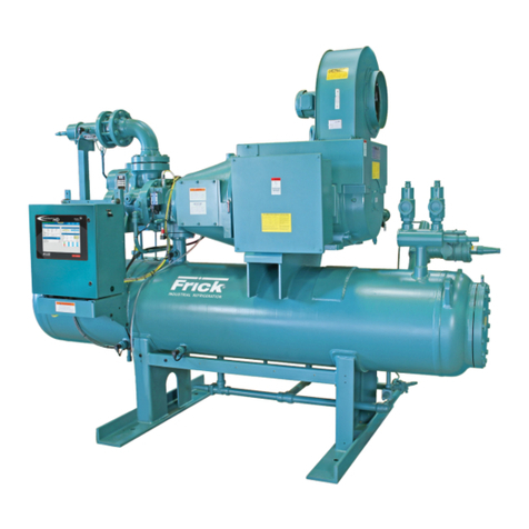
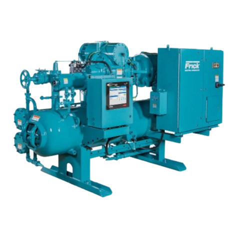
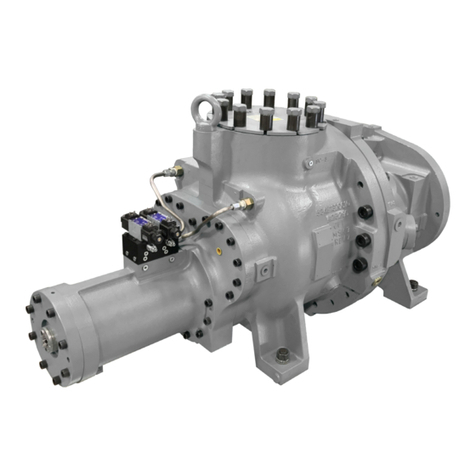
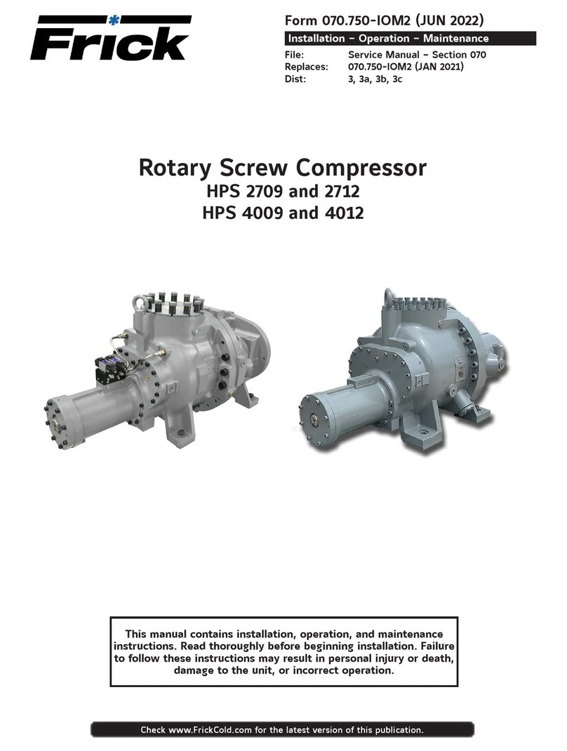
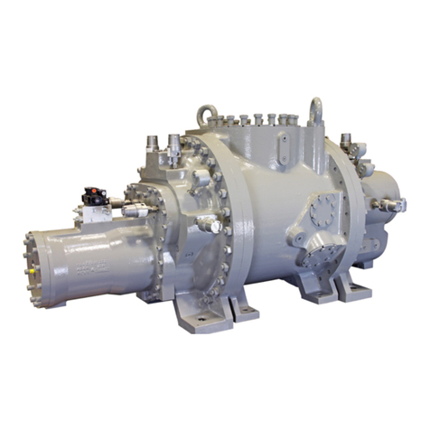
Frick RWB II Owner's manual

Installation - Operation - Maintenance
ROTARY SCREW COMPRESSOR UNITS
ALL REFRIGERANTS
MODELS
60 through 480
THIS MANUAL CONTAINS RIGGING, ASSEMBLY, START-UP, AND
MAINTENANCEINSTRUCTIONS. READTHOROUGHLYBEFOREBE-
GINNING INSTALLATION. FAILURETO FOLLOWTHESE INSTRUC-
TIONS COULD RESULT IN DAMAGE OR IMPROPER OPERATION
OFTHE UNIT.
S70-200 IOM/OCT 2004
File: SERVICE MANUAL - Section 70
Replaces: S70-200 IOM/AUG 2001
Dist: 3, 3a, 3b, 3c

RWB II ROTARY SCREW COMPRESSOR UNITS
INSTALLATION - OPERATION - MAINTENANCE
S70-200 IOM
Page 2
Contents
Maintenance
GENERAL INFORMATION..............................................25
NORMAL MAINTENANCE OPERATIONS......................25
GENERAL MAINTENANCE............................................25
COMPRESSOR SHUTDOWN and START-UP................25
GENERAL INSTRUCTIONS FOR REPLACING
COMPRESSOR UNIT COMPONENTS.....................26
OIL FILTER (OF-1) MAIN SINGLE/DUAL .......................26
STRAINER - DEMAND OIL PUMP .................................26
STRAINER - LIQUID INJECTION...................................27
COALESCER FILTER ELEMENT(S)...............................27
CHANGING OIL ..............................................................27
DEMAND PUMP DISASSEMBLY....................................28
TROUBLESHOOTING THE DEMAND PUMP.................30
RECOMMENDED MAINTENANCE PROGRAM.............32
VIBRATION ANALYSIS ...................................................32
MOTOR BEARINGS........................................................32
OIL QUALITY and ANALYSIS .........................................32
OPERATING LOG...........................................................33
MAINTENANCE SCHEDULE..........................................33
TROUBLESHOOTING GUIDE........................................34
ABNORMAL OPERATION
ANALYSIS and CORRECTION................................34
SERVICING THE COLD-START VALVE..........................34
PRESSURE TRANSDUCERS - TESTING......................34
PRESSURE TRANSDUCERS - REPLACEMENT ..........35
SV POSITION POTENTIOMETER
REPLACEMENT AND ADJUSTMENT.....................36
VOLUMIZER®POTENTIOMETER
REPLACEMENT AND ADJUSTMENT.....................36
TEMPERATURE and/or PRESSURE ADJUSTMENT.....37
OIL LEVEL TRANSMITTER REPLACEMENT................37
TROUBLESHOOTING
RWB II COMPRESSOR...........................................37
OIL SEPARATION SYSTEM ....................................38
HYDRAULIC SYSTEM.............................................38
LIQUID INJECTION OIL COOLING SYSTEM.........39
DEMAND PUMP SYSTEM.......................................39
THERMAL EXPANSION VALVES....................................40
JORDANTEMPERATURE REGULATOR VALVE.............41
BARE COMPRESSOR MOUNTING...............................42
SHUTDOWN DUE TO IMPROPER OIL PRESSURE ....42
GREASE COMPATIBILITY..............................................42
NLGI Grease Compatibility Chart....................................42
P & I DIAGRAMS............................................................43
PROPER INSTALLATION OF ELECTRONIC EQUIP-
MENT IN AN INDUSTRIAL ENVIRONMENT..........47
FORMS
OPERATING LOG SHEET.......................................50
COMPRESSOR PRESTART CHECKLIST ..............51
START-UP REPORT ................................................52
VIBRATION DATA SHEET........................................54
RECOMMENDED SPARE PARTS..................................55
Indicates an imminently hazardous situation which, if not avoided, will result in death or serious
injury.
Indicates a potentially hazardous situation or practice which, if not avoided, will result in death
or serious injury.
SAFETY PRECAUTION DEFINITIONS
Indicates a potentially hazardous situation or practice which, if not avoided, will result in dam-
age to equipment and/or minor injury.
NOTE: Indicates an operating procedure, practice, etc., or portion thereof which is essential to highlight.
PREFACE..........................................................................3
DESIGN LIMITATIONS......................................................3
JOB INSPECTION.............................................................3
TRANSIT DAMAGE CLAIMS ............................................3
COMPRESSOR and UNIT IDENTIFICATION...................3
Installation
FOUNDATION ...................................................................4
RIGGING and HANDLING ................................................4
SKID REMOVAL................................................................4
MOTOR MOUNTING.........................................................5
CHECKING MOTOR/COMPRESSOR ROTATION..............5
COMPRESSOR/MOTOR COUPLINGS INSTALLATION...5
COUPLING ALIGNMENT PROCEDURE..........................7
HOT ALIGNMENT OF COMPRESSOR/MOTOR................9
OIL PUMP COUPLING......................................................9
HOLDING CHARGE AND STORAGE...............................9
COMPRESSOR UNIT OIL ................................................9
OIL CHARGE ....................................................................9
OIL HEATER(S).................................................................9
OIL FILTER(S).................................................................10
THERMOSYPHON OIL COOLING..................................10
LIQUID INJECTION OIL COOLING (OPTIONAL)...........11
LIQUID LINE SIZES/RECEIVER VOLUME.....................12
WATER-COOLED OIL COOLING (Optional)...................12
ECONOMIZER - HIGH STAGE (OPTIONAL)..................12
ELECTRICAL ..................................................................14
MOTOR STARTER PACKAGE ........................................14
MINIMUM BURDEN RATINGS........................................15
CONTROL POWER REGULATOR..................................16
Operation
OPERATION and START-UP INSTRUCTIONS...............17
TDSH COMPRESSOR....................................................17
COMPRESSOR LUBRICATION SYSTEM......................17
NO PUMP OIL SYSTEM.................................................17
COLD-START SYSTEM ..................................................17
DEMAND PUMP OIL SYSTEM.......................................18
COMPRESSOR OIL SEPARATION SYSTEM.................18
COMPRESSOR HYDRAULIC SYSTEM.........................19
VOLUMIZER®VOLUME RATIO CONTROL....................19
COMPRESSOR OIL COOLING SYSTEMS....................20
SINGLE-PORT LIQUID INJECTION ...............................20
RWB II BOOSTER OR SWING DUTY APPLICATION....20
DUAL-PORT LIQUID INJECTION...................................20
LIQUID INJECTION ADJUSTMENT PROCEDURE .......20
QUANTUM™ EZ-COOL™LIQUID INJECTION
ADJUSTMENT PROCEDURE.................................21
SUCTION CHECK VALVE...............................................22
SUCTION CHECK VALVE BYPASS................................23
LOW AMBIENT OPERATION..........................................23
SUCTION CHECK VALVEPOWER ASSIST KIT.............23
INITIAL START-UP ..........................................................24
INITIAL START-UP PROCEDURE ..................................24
NORMAL START-UP PROCEDURE...............................24

RWB II ROTARY SCREW COMPRESSOR UNITS
GENERAL INFORMATION S70-200 IOM
Page 3
PREFACE
This manual has been prepared to acquaint the owner and
serviceman with the INSTALLATION, OPERATION, and
MAINTENANCE procedures as recommended by Frick®for
RWB II Rotary Screw Compressor Units.
For information about the functions of the electrical control
panel,communications,specifications, andwiringdiagrams,
see S90-010 O, M, and CS (Quantum™panel) or S70-200
OM (Plus panel).
Itismost importantthat these unitsbe properly appliedtoan
adequately controlled refrigeration system.Your authorized
Frickrepresentativeshould beconsultedforexpert guidance
in this determination.
Proper performance and continued satisfaction with these
units is dependent upon:
CORRECT INSTALLATION
PROPER OPERATION
REGULAR, SYSTEMATIC MAINTENANCE
To ensure correctinstallation andapplication,the equipment
must be properly selected and connected to a properly de-
signed and installed system.The Engineering plans, piping
layouts, etc. must be detailed in accordance with the best
practicesand localcodes,such asthose outlinedin ASHRAE
literature.
A refrigeration compressor is aVAPOR PUMP.To be certain
that it is not being subjected to liquid refrigerant carryover it
is necessary that refrigerant controls are carefully selected
and in good operating condition;the piping is properly sized
and traps, if necessary, are correctly arranged; the suction
line has an accumulator or slugging protection; that load
surgesareknownand provisionsmade for control;operating
cycles and defrosting periods are reasonable;and that high
side condensers are sized within system and compressor
design limits.
Itisrecommendedthatthe enteringvaportemperature tothe
compressor be superheated to 10°F above the refrigerant
saturation temperature. This assures that all refrigerant at
the compressor suction is in the vapor state.
DESIGN LIMITATIONS
The compressor units are designed for operation within
the pressure and temperature limits as shown in Frick Pub.
E70-200 SED.
JOB INSPECTION
Immediately upon arrival examine all crates, boxes and
exposed compressor and component surfaces for damage.
Unpack all items and check against shipping lists for any
possible shortage. Examine all items for damage in transit.
TRANSIT DAMAGE CLAIMS
All claims must be made by consignee. This is an ICC re-
quirement. Request immediate inspection by the agent of the
carrier and be sure the proper claim forms are executed.
Report damage or shortage claims immediately to Frick,
Sales Administration Department, in Waynesboro, PA.
COMPRESSOR and UNIT IDENTIFICATION
Each compressor unit has 2 identification data plates.The
compressor data plate containing compressor model and
serial number is mounted on the compressor body.The unit
data plate containing unit model, serial number and Frick
sales order number is mounted on the side of the motor
base.
NOTE: When inquiring about the compressor or unit,
or ordering repair parts, provide the MODEL, SERIAL,
and FRICK SALES ORDER NUMBERS from these data
plates.
UNIT DATA PLATE
COMPRESSOR DATA PLATE

RWB II ROTARY SCREW COMPRESSOR UNITS
INSTALLATION
S70-200 IOM
Page 4
ALLOWABLE FLANGE LOADS
NOZ. MOMENTS (ft-lbf) LOAD (lbf)
SIZE AXIAL VERT. LAT. AXIAL VERT. LAT.
NPS MRM
C ML P VC VL
1 25 25 25 50 50 50
1.25 25 25 25 50 50 50
1.5 50 40 40 100 75 75
2 100 70 70 150 125 125
3 250 175 175 225 250 250
4 400 200 200 300 400 400
5 425 400 400 400 450 450
6 1000 750 750 650 650 650
8 1500 1000 1000 1500 900 900
10 1500 1200 1200 1500 1200 1200
12 1500 1500 1500 1500 1500 1500
14 2000 1800 1800 1700 2000 2000
FOUNDATION
Each RWB II Rotary Screw Compressor Unit is shipped
mounted on a wood skid which must be removed prior to unit
installation.
Allow space for servicing both ends
of the unit. A minimum of 36 inches
is recommended.
The first requirement of the compressor foundation is that it
must be able to support the weight of the compressor pack-
age including coolers, oil, and refrigerant charge. Screw
compressors are capable of converting large quantities of
shaft power into gas compression in a relatively small space
andamass isrequired to effectivelydampen theserelatively
high frequency vibrations.
Firmly anchoring the compressor package to a suitable
foundation by proper application of grout and elimination of
piping stress imposed on the compressor is the best insur-
ance for a trouble free installation. Use only the certified
general arrangement drawings from Frick Co. to determine
the mounting foot locations and to allow for recommended
clearances around the unit for ease of operation and servic-
ing. Foundations must be in compliance with local building
codes and materials should be of industrial quality.
The floor should be a minimum of 6 inches of reinforced con-
crete and housekeeping pads are recommended. Anchor
bolts are required to firmly tie the unit to the floor. Once the
unit is rigged into place (See RIGGING and HANDLING),
the feet must then be shimmed in order to level the unit. The
shims should be placed to position the feet roughly one inch
above the housekeeping pad to allow room for grouting. An
expansion-type epoxy grout must be worked under all areas
of the base with no voids and be allowed to settle with a slight
outward slope so oil and water can run off of the base.
When installing on a steel base, the following guidelines
should be implemented to properly design the system base:
1. Use I-beams in the skid where the screw compressor will
be attached to the system base. They should run parallel to
the package feet and support the feet for their full length.
2.The compressor unit feet should be continuously welded to
the system base at all points of contact.
3. The compressor unit should not be mounted on vibration
isolators in order to hold down package vibration levels.
4.The customer’s foundation for the system base should fully
support the system base under all areas, but most certainly
under the I-beams that support the compressor package.
Wheninstalling onthe upperfloorsofbuildings,extraprecau-
tions should be taken to prevent normal package vibration
from being transferred to the building structure. It may be
necessaryto userubberor springisolators, ora combination
of both, to prevent the transmission of compressor vibration
directlyto thestructure. However,thismayincreasepackage
vibrationlevelsbecause thecompressorisnotincontactwith
any damping mass. The mounting and support of suction
and discharge lines is also very important. Rubber or spring
pipe supports may be required to avoid exciting the building
structure atany pipesupports closeto thecompressorpack-
age. It is best to employ a vibration expert in the design of
a proper mounting arrangement.
Inanyscrewcompressorinstallation,suction anddischargelines
should be supported in pipe hangers (preferably within 2 ft. of
vertical pipe run) so that the lines won’t move if disconnected
from the compressor. See table for Allowable Flange Loads.
A licensed architect should be consulted to determine the
proper foundation requirements for any large engine or
turbine drive.
When applying screw compressors at high pressures, the
customer must be prepared for package vibration and noise
higher thanthe values predictedfornormal refrigeration duty.
Properfoundationsand properinstallation methodsarevital;
and even then, sound attenuation or noise curtains may be
required to reduce noise to desired levels.
For more detailed information on Screw Compressor Foun-
dations, please request Frick publication S70-210 IB.
RIGGING and HANDLING
THIS SCREW COMPRESSOR
PACKAGE MAY BE TOP-HEAVY.
USE CAUTION IN RIGGING AND
HANDLING.
The unit can be moved with rigging, using a crane or forklift,
by hooking into the four lifting eyes on the compressor and
motor bases. If no motor is mounted, the lifting ring should
be moved to the compressor side of the center of the unit
because 60 percent of the weight is toward the compressor
end.If a motor is mounted appropriate adjustment in the lift-
ing point should be made to compensate for motor weight.
Adjustment of the lifting point must also be made for any
additions to the standard package such as an external oil
cooler, etc., as the center of balance will be effected.
Theunit canbe movedwithaforkliftbyforkingundertheskid,
or it can be skidded into place with pinch bars by pushing
against the skid. NEVER MOVE THE UNIT BY PUSHING
OR FORKING AGAINSTTHE SEPARATOR SHELL OR ITS
MOUNTING SUPPORTS.
SKID REMOVAL
If the unit is rigged into place the skid can be removed
by taking off the nuts and bolts that are fastening the unit
mounting supports to the skid before lowering the unit onto
the mounting surface.
If the unit is skidded into place remove the cross members
from the skid and remove the nuts anchoring the unit to the
skid.Using a5 tonjackunder theseparatorraisetheunitat the
compressorenduntil itclears thetwomountingbolts. Spread
theskidto clearthe unitmountingsupport, thenlowertheunit
to the surface. Repeat procedure on opposite end.

RWB II ROTARY SCREW COMPRESSOR UNITS
INSTALLATION S70-200 IOM
Page 5
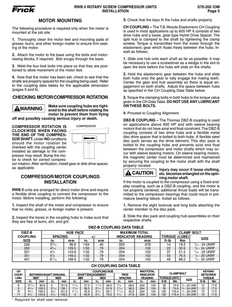
226 313/16 96.8 1/64 .40 .003 .076 14 19.5
5/16 - 24 UNRF
263 45/16 109.5 1/32 .79 .004 .102 22 30.6
3/8- 24 UNRF
301 47/8123.8 1/32 .79 .004 .102 37 51.5
7/16 - 20 UNRF
351 57/8149.2 1/32 .79 .004 .102 55 76.5
1/2- 20 UNRF
401 611/16 169.9 1/32 .79 .004 .102 49 68.2
1/2- 20 UNRF
8 313/16 96.8 4 101.6 11/16 27.0 113/16 46.0 11/828.6 .004 .104 55 74.6
3/8- 24 UNF 13 17.6
9 45/16 109.5 57/16 138.1 17/16 36.5 23/16 61.9 17/16 36.5 .004 .104 55 74.6
3/8- 24 UNF 13 17.6
10 45/16 109.5 63/8161.9 111/16 42.9 29/16 65.1 111/16 42.9 .004 .104 130 176.4
1/2- 20 UNF 13 17.6
11 47/8123.8 57/8149.2 2 50.8 27/873.0 17/847.6 .004 .104 130 176.4
1/2- 20 UNF 13 17.6
DBZ-B HUB FACE MAXIMUMTOTAL CLAMP BOLT
COUPLING SPACING +/- INDICATOR READING TORQUE (LUBE) SIZE
SIZE in. mm in. mm in. mm ft-lb Nm
MOTOR MOUNTING
The following procedure is required only when the motor is
mounted at the job site.
1. Thoroughly clean the motor feet and mounting pads of
grease, burrs, and other foreign matter to ensure firm seat-
ing of the motor.
2. Attach the motor to the base using the bolts and motor-
raising blocks, if required. Bolt snugly through the base.
3. Weld the four kick bolts into place so that they are posi-
tioned to allow movement of the motor feet.
4. Now that the motor has been set, check to see that the
shaftsareproperly spacedforthe couplingbeing used. Re-
fer to the coupling data tables for the applicable dimension
(pages 5 and 6).
CHECKING MOTOR/COMPRESSOR ROTATION
Make sure coupling hubs are tight-
ened to theshaft before rotating the
motor to prevent them from flying
off and possibly causing serious injury or death.
COMPRESSOR ROTATION IS
CLOCKWISE WHEN FACING
THEENDOFTHECOMPRESSOR
SHAFT. Under NO conditions
should the motor rotation be
checked with the coupling center
installed as damage to the com-
pressormayresult. Bump themo-
torto checkforcorrect compressor
rotation. After verifi cation, install
gear or disk drive spacer, as applicable.
COMPRESSOR/MOTOR COUPLINGS
INSTALLATION
RWB II units are arranged for direct motor drive and require
a flexible drive coupling to connect the compressor to the
motor.Before installing, perform the following:
1. Inspect the shaft of the motor and compressor to ensure
that no nicks, grease, or foreign matter is present.
2. Inspect the bores in the coupling hubs to make sure that
they are free of burrs, dirt, and grit.
CH COUPLING DATATABLE
3. Check that the keys fit the hubs and shafts properly.
CH COUPLING – TheT.B.Woods Elastomeric CH Coupling
is used in most applications up to 600 HP. It consists of two
drive hubs and a loose, gear-type Hytrel Drive Spacer.The
split hub is clamped to the shaft by tightening the clamp
screws. Torque is transmitted from the motor through the
elastomeric gearwhich floatsfreely betweenthe hubs.Install
as follows:
1. Slide one hub onto each shaft as far as possible. It may
be necessary to use a screwdriver as a wedge in the slot to
open the bore before the hubs will slide on the shafts.
2. Holdthe elastomeric gearbetweenthehubsandslideboth
hubs onto the gear to fully engage the mating teeth.Center
the gear and hub assembly so there is equal engagement
on both shafts. Adjust the space between hubs as specified
in the CH Coupling Data Table below.
3.Torque the clamping bolts in both hubs to the torque value
givenintheCH DataTable.DO NOT USE ANY LUBRICANT
ONTHESE BOLTS.
4. Proceed to Coupling Alignment.
DBZ-B COUPLING – The Thomas DBZ-B coupling is used
on applications above 600 HP and with sleeve bearing mo-
tors that do not have axial end float constraint.The DBZ-B
coupling consists of two drive hubs and a flexible metal disc
drive spacer that is bolted to both hubs.A flexible steel disc
pack serves as the drive element.This disc pack is bolted to
the coupling hubs and prevents axial end float between the
compressor and motor shafts which may occur with sleeve
bearing motors. On sleeve bearing motors, the magnetic
center must be determined and maintained by securing the
coupling to the motor shaft with the shaft properly located.
Injury may occur if loose clothing,
etc. becomes entangled on the
spinning motor shaft.
If the motor is coupled to the compressor using a fixed-end-
playcoupling,suchasaDBZ-Bcoupling,and themotor isnot
properly centered, additional thrust loads will be transmitted
to the compressor bearings that could result in premature
bearing failure. Install as follows:
1. Remove the eight locknuts and long bolts attaching the
center member to the disc pack.
2. Slide the disc pack and coupling hub assemblies on their
respective shafts.
DBZ-B COUPLING DATATABLE
* Required for shaft seal removal.
CH COUPLING HUB MAXTOTAL KEYWAY
COUP- BETWEEN SHAFT SPACING SHAFT ENGAGEMENT FACE INDICATOR CLAMP BOLT SETSCREW
LING MIN* MAX MIN MAX SPACING READING TORQUE (DRY) TORQUE
SIZE in. mm in. mm in. mm in. mm in. mm in. mm ft-lb Nm SIZE ft-lb Nm
Other manuals for RWB II
1
Table of contents
Other Frick Air Compressor manuals

Frick
Frick RWB II 60 Owner's manual

Frick
Frick RWB II 496 Owner's manual

Frick
Frick SGC 1913 User manual

Frick
Frick XJS 95 User manual

Frick
Frick RWF Series Owner's manual

Frick
Frick TDS Series Owner's manual

Frick
Frick RXB PLUS Owner's manual

Frick
Frick XJS 95M Owner's manual

Frick
Frick RWB II User manual

Frick
Frick SBTP 355 Series Owner's manual