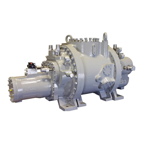
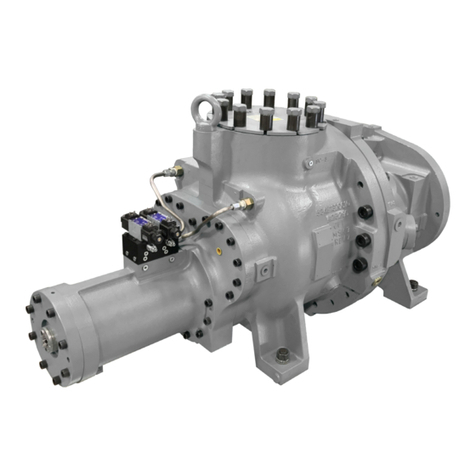
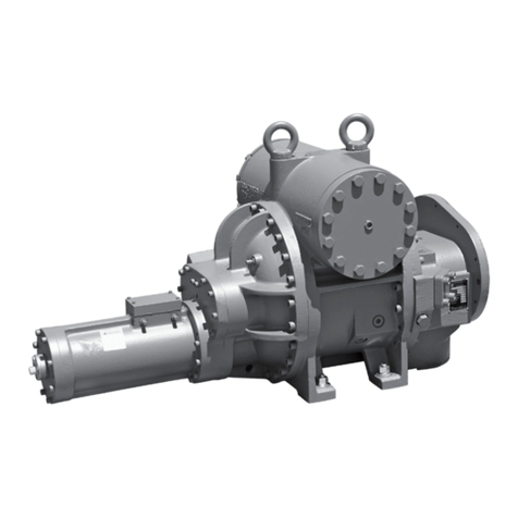
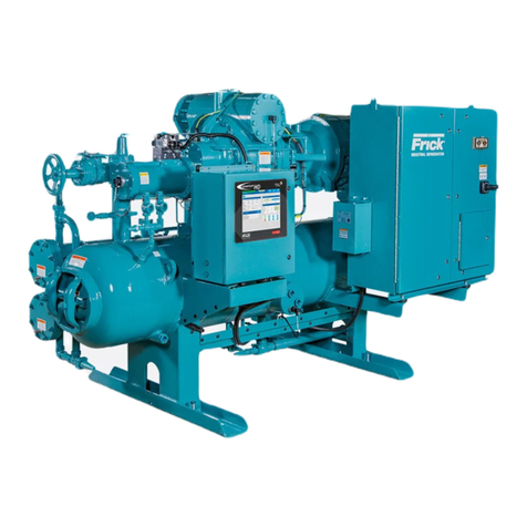
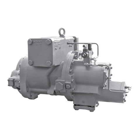
Frick TDS Series Owner's manual

TDS_
Rotary Screw Compressor
Models TDS_163 - TDS_355
This manual contains installation, operation, and maintenance
instructions. Read thoroughly before beginning installation. Failure
to follow these instructions may result in personal injury or death,
damage to the unit, or incorrect operation.
Form 070.250-IOM1 (NOV 2013)
Installation – Operation – Maintenance
File: Service Manual – Section 070
Replaces: Nothing
Distribution: 3, 3a, 3b, 3c
Revised: April 2016, p. 2, 8, 16
October 31, 2022
Check www.FrickCold.com for the latest version of this publication.

070.250-IOM1 (NOV 2013)
Page 2
TDS_ Rotary Screw Compressor
Installation - Operation - Maintenance
Table of Contents
General information
Preface .............................................................................3
Design limitations .............................................................3
Job inspection ..................................................................3
Standard bare compressor ...............................................3
Transit damage claims ...................................................... 3
Compressor identication ................................................3
Long-term storage............................................................4
Preparing compressor for storage................................ 5
Maintaining compressor ............................................... 5
Description........................................................................5
TDS_ compressor ........................................................5
Compressor lubrication system ...................................5
Oil pump.......................................................................6
Construction details ..........................................................6
Installation
Design limits .....................................................................7
Outline dimensions ...........................................................7
Holding charge and storage ............................................12
Rigging and handling.......................................................12
Lifting instructions......................................................12
Foundation .....................................................................12
Customer connections ....................................................13
Oil system requirements .................................................13
Oil selection ...............................................................13
Oil pressure ................................................................13
Oil cooling requirements ............................................13
Oil lters ....................................................................14
Oil pump .........................................................................14
Oil heaters ..................................................................... 14
Compressor oil ................................................................14
Compressor..................................................................... 14
Motor mounting (foot mounted only) ......................... 14
Compressor/motor coupling requirements. ................14
Coupling alignment requirements...............................14
Coupling alignment procedure ........................................15
Hot alignment of compressor/motor ............................... 15
SV position potentiometer
replacement and adjustment....................................15
Volumizer potentiometer
replacement and adjustment....................................16
Compressor hydraulic system..........................................16
Volumizer volume ratio control ...................................... 17
Vi increase .................................................................17
Vi decrease ...............................................................17
Low ambient operation .................................................. 17
Balance piston pressure regulator
for TDSH 355 compressors ......................................17
Operation
Operation and start-up instructions ............................... 18
Initial start-up ........................................................... 18
Initial start-up procedure ..........................................18
Normal start-up procedure ........................................18
Maintenance
General information .......................................................19
Normal maintenance operations .................................... 19
General maintenance..................................................19
Changing oil ...............................................................19
Recommended maintenance program .......................20
Vibration analysis ...........................................................20
Oil quality and analysis ................................................... 20
Maintenance schedule..................................................... 20
Operating log ............................................................ 21
Troubleshooting guide .................................................... 21
Abnormal operation analysis and correction .............21
Bare compressor replacement ....................................... 21
Shutdown due to improper oil pressure (high-stage and
booster) ..................................................................22
Troubleshooting the TDS_ compressor (Frick RWB II
package) ..................................................................22
Troubleshooting the hydraulic system ............................. 22
Troubleshooting the oil pump and system ...................... 23
Read this rst: compressor prestart checklist ................. 24
Vibration data sheet........................................................ 26
Indicates an imminently hazardous situation which, if not avoided, will result in death or serious
injury.
Indicates a potentially hazardous situation or practice which, if not avoided, will result in death or
serious injury.
Safety precaution denitions
Indicates a potentially hazardous situation or practice which, if not avoided, will result in damage
to equipment and/or minor injury.
Indicates an operating procedure, practice, etc., or portion thereof which is essential to highlight.
Referenced manuals:
090.020-M: Quantum LX Maintenance
160.802-SPC: CompressorOilSpecications
090.022-O: Quantum HD Operation
WARNING
CAUTION
DANGER
NOTICE
070.250-IOM1 (NOV 2013)
Page 3
TDS_ Rotary Screw Compressor
Installation - Operation - Maintenance
Note: The information contained in this document is
subject to change without notice
General information
Preface
This manual has been prepared to acquaint the owner and
serviceman with the installation, operation, and mainte-
nance procedures as recommended by Johnson Controls-
Frick®for TDS_ Rotary Screw Compressors.
It is most important that these compressors be properly
applied to an adequately controlled refrigerant or gas
system. Your authorized Johnson Controls-Frick represen-
tative should be consulted for his expert guidance in this
determination.
Proper performance and continued satisfaction with these
units is dependent upon:
• Correct installation
• Proper operation
• Regular, systematic maintenance
To ensure correct installation and application, the equip-
ment must be properly selected and connected to a prop-
erly designed and installed system. The Engineering plans,
piping layouts, etc. must be detailed in accordance with
the best practices and local codes, such as those outlined
in ASHRAE literature.
A screw compressor is a vapor pump. To be certain that
it is not being subjected to pumping liquid, it is necessary
that controls are carefully selected and in good operat-
ing condition; the piping is properly sized and traps, if
necessary, are correctly arranged; the suction line has an
accumulator or slugging protection; that load surges are
known and provisions are made for control; operating
cycles and stand still periods are reasonable; and that high
side components are sized within system and compressor
design limits.
It is required that the discharge temperature be kept high
enough to prevent condensation of any moisture in the
compressor and oil separator.
Design limitations
TDS_ compressors are designed for operation within the
pressureandtemperaturelimitswhicharespeciedby
Johnson Controls-Frick and the Johnson Controls-Frick
selection software COOLWARE™. They are primarily used
for compressing refrigerant gas and most hydrocarbon
gasses.
If your application is for sour gas, there are special re-
quirements to protect the compressor. Contact Johnson
Controls - Frick Compressor Engineering for application
details.
Job inspection
Immediately upon delivery examine all crates, boxes and
exposed compressor and component surfaces for damage.
Unpack all items and check against shipping lists for any
discrepancy. Examine all items for damage in transit.
Standard bare compressor
Items not included with the bare compressor that are
available as sales order options: Solenoid Valves, Tank
Drain Tubing (T connection), Oil Feed Line (P connection),
Connection Fittings, Coupling.
Transit damage claims
All claims must be made by the consignee. This is an ICC
requirement. Request immediate inspection by the agent
of the carrier and be sure the proper claim forms are ex-
ecuted. Report damage or shortage claims immediately to
Johnson Controls-Frick Sales Administration Department,
in Waynesboro, PA.
Compressor identication
Each compressor has an identicationdataplate,contain-
ing compressor model and serial number mounted on the
compressor body.
NOTICE
When inquiring about the compressor or unit, or order-
ing repair parts, provide the model, serial, and Johnson
Controls - Frick sales order numbers from the data plate.
See Figure 1.
Figure 1: Compressor identication data plate
Rotaryscrewcompressorserialnumbersaredenedbythe
following information:
Example: 10240A90000015Z
Plant Decade Month Year Global
seq. no.
Additional
remarks
1024 0 A 9 0000015 Z
Plant: 1024 = Waynesboro, 1153 = Monterrey
Month:
A = JAN, B = FEB, C = MAR, D = APR, E = MAY, F = JUN,
G = JUL, H = AUG, K = SEP, L = OCT, M = NOV, N = DEC.

070.250-IOM1 (NOV 2013)
Page 4
TDS_ Rotary Screw Compressor
Installation - Operation - Maintenance
Additional Remarks:
R = Remanufactured;
R1 = Rebuild;
R2 = Rebuild Plus;
Z =DeviationfromStandardConguration.
The name plates in Figure 2 show which refrigerants are
compatible with the compressor as manufactured.
Figure 2: Refrigerant name plates
Long-term storage
Long term storage (6 months to 5 years) provisions are re-
quired, regardless of storage environment, if start-up and/
or useful operation does not occur within six (6) months of
equipment shipment. Special provisions may be required
for storage of less than six (6) months if the storage area
is subject to unusual environment such as high humidity,
large changes in temperature, dusty atmosphere, etc.
The standard Johnson Controls-Frick Warranty for an
TDS_ screw compressor covers twelve (12) months from
start-up or 18 months from shipment, whichever comes
rst.Itisrecommendedthatarrangementsbemadewith
the local Johnson Controls-Frick service organization
(arranged through factory service) regarding surveillance
and maintenance during the storage period. It will be
the customer’s responsibility to submit a monthly report
showing the condition of the unit and noting any discrep-
ancies to the guidelines listed herein. Failure to comply
with this Long Term Storage Recommendation may void
the warranty.
Compressor model Rotor
diameter
Rotor Max speed Geometrical swept volume,
drive shaft end
Displacement
3550 rpm 2950 rpm
mm L/D rpm ft³/rev m³/rev cfm m³/h
TDSH 163S 163 1.35 4,500 0.10069 0.002849 357 504
TDSH 163L 163 1.7 4,500 0.12679 0.003588 450 635
TDSH/TDSL 193S 193 1.35 4,500 0.16653 0.004713 591 834
TDSH/TDSL 193L 193 1.8 4,500 0.22204 0.006284 788 1,112
TDSH/TDSL 233S 233 1.35 4,500 0.29301 0.008292 1,040 1,468
TDSH/TDSL 233L 233 1.7 4,500 0.36897 0.010442 1,310 1,848
TDSH 233XL 233 2.1 4,500 0.45580 0.012899 1,618 2,283
TDSH/TDSL 283S 283 1.35 4,200 0.52501 0.014858 1,864 2,630
TDSH/TDSL 283L 283 1.7 4,200 0.66115 0.018711 2,347 3,312
TDSH 283SX 283 2.1 4,200 0.79546 0.022512 2,824 3,985
TDSH/B 355S 355 1.1 4,200 0.89858 0.025430 3,190 4,501
TDSH/B 355L 355 1.5 4,200 1.12154 0.031739 3,981 5,618
TDSH/B 355XL 355 1.9 4,200 1.42748 0.040398 5,068 7,150
TDSB 355U 355 2.4 4,200 1.80328 0.051033 6,402 9,033
Table 2: Compressor and packaged equipment storage log
Model Serial no. Compressor* shaft
rotation 1½ turn
Rotor
housing
charge
Charge
added
Visual
inspection
per QAI-3
Charge Checked by Date
*Compressor, Motor, Oil Pump and Refrigerant Pump
Table 1: Geometrical swept volume

070.250-IOM1 (NOV 2013)
Page 5
TDS_ Rotary Screw Compressor
Installation - Operation - Maintenance
Long term storage of equipment may lead to the deterio-
ration of components over the period of time. Synthetic
components in the compressor may deteriorate over time
eveniftheyarekeptoodedwithoil.Awarmanddry
environment is essential to minimize environmental and
corrosion damage. Long-term storage of the affected
equipment at a customer’s site may involve additional
requirements and interested parties should refer to the
Johnson Controls web site,
www.johnsoncontrols.com/frick,forspecicinstructions.
The following guidelines must be followed to maintain the
screw compressor warranty.
Preparing the compressor for storage
1. Evacuate the compressor to remove moisture.
2. Connect the evacuation lines to the three Schrader ac-
cess valves provided with the compressor. One valve is
connected to the compressor suction and the other two
valves are located at the block on the cylinder.
3. Break the vacuum with dry nitrogen and bring pressure
to 0 psig
4. Pump oil into the SM1. Use break-in oil P/N
111Q0831809 for storage purposes. The amounts of oil
needed per compressor are:
• 163 mm - 8 gal
• 193 mm - 12 gal
• 233 mm - 15 gal
• 283 mm - 25 gal
• 355 mm - 35 gal
5. After the compressor is oil charged, pressurize the com-
pressor to 15 psig with nitrogen.
Maintaining the compressor
1. Maintain the 5 psig to 15 psig nitrogen charge, but ide-
ally at 15 psig.
2. Rotate the male rotor shaft every two weeks. Mark the
shaft to ensure the rotor does not return to the original
position..
3. Store the compressor inside a dry building environment.
4. Grease the male rotor shaft to prevent rust.
5. Record all information in a compressor long-term
storage log. See Table 2.
Contact Johnson Controls-Frick Service with any ques-
tions regarding long term storage.
Description
TDS_ compressor
The Frick TDS_ rotary screw compressor utilizes mating
asymmetricalprolehelicalrotorstoprovideacontinu-
ousowofrefrigerantvaporandisdesignedforbothhigh
pressure and low pressure applications. The compressor
incorporates the following features:
1. High capacity roller bearings to carry radial loads at
both the inlet and outlet ends of the compressor.
2. Heavy-duty, two-point or four-point angular contact
ball bearings to carry axial loads are mounted at the dis-
charge end of compressor.
3. Balance piston located in the inlet end of the compres-
sor to reduce axial loads on the axial load bearings and
increase bearing life.
4.Moveableslidevalvetoprovideinnitestepcapacity
control from 100 to 10%.
5.
Volumizervolumeratiocontroltoallowinnitelyvariable
volume ratio from 2.2 to 5.0 during compressor operation
for all models except TDSH 283SX which is 2.2 to 4.2
.
6. A hydraulic unloader cylinder to operate the slide stop
and slide valve.
7. Bearing and casing design for 400 PSI discharge pres-
sure. This PSI rating applies only to the compressor and
doesnotreectthedesignpressureofthevarioussystem
components.
8. All bearing and control oil vented to closed thread in the
compressor instead of suction port to avoid performance
penalties from superheating suction gas.
9. Shaft seal design to maintain operating pressure on seal
well below discharge pressure, for increased seal life.
10. Oil injected into the rotors to maintain good volumet-
ricandadiabaticefciencyevenatveryhighcompression
ratios.
11. Shaft rotation clockwise facing compressor shaft, suit-
able for all types of drives.
WARNING
Compressor rotation is clockwise when facing the
compressor drive shaft. The compressor should never
be operated in reverse rotation, as bearing damage
will result.
12. Dual compressor casing design for very low airborne
noise transmission.
Compressor lubrication system
The lubrication system on a TDS_ screw compressor
performs several functions:
1. Provides lubrication to bearings and seal.
2. Provides a cushion between the rotors to minimize noise
and vibrations.
3. Helps keep the compressor cool and prevents overheating.
This manual suits for next models
25
Table of contents
Other Frick Air Compressor manuals

Frick
Frick RWB II User manual

Frick
Frick XJS 95 User manual

Frick
Frick RWB II 60 Owner's manual

Frick
Frick RWB II 496 Owner's manual

Frick
Frick SGC 1913 User manual

Frick
Frick RXB PLUS Owner's manual

Frick
Frick HPS 2709 Owner's manual

Frick
Frick XJS 95M Owner's manual

Frick
Frick HPS 2709 User manual

Frick
Frick RWF Series Owner's manual