070-450 IOM (NOV 13)
Page 5
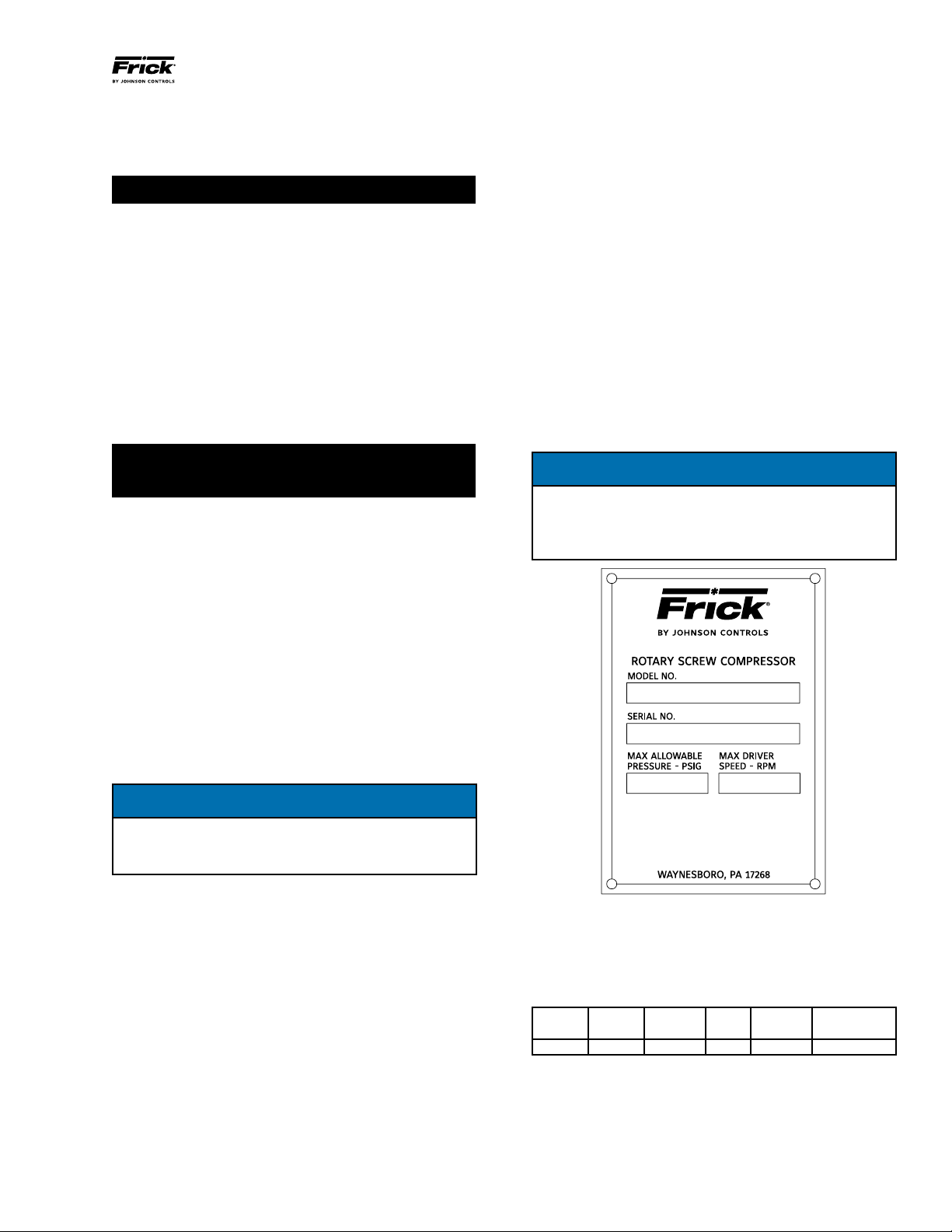
XJF ROTARY SCREW COMPRESSOR
INSTALLATION - OPERATION - MAINTENANCE
Bare Compressors\General\Warranties\Screw Compressor
Purchased for Long Term Storage).
The following guidelines must be followed to maintain the
SCREW COMPRESSOR WARRANTY.
PREPARING COMPRESSOR FOR STORAGE
Evacuate compressor to remove moisture. Evacuation lines
are to be connected to port SM1. Evacuation lines are to be
connected to the three Schrader valves provided with the
compressor. One valve is connected to compressor suction.
The other two valves are located at the block on the cylinder.
Break vacuum with dry nitrogen and bring pressure to 0 psig.
Pump oil into the same ports mentioned in step 1. Johnson
Controls-Frick recommends break-in oil P/N 111Q0831809
for storage purposes. The amounts of oil needed per
compressor are:
95mm - 2Gal
120mm - 3Gal
151mm - 8Gal
After compressor is oil charged, pressurize compressor to
15 psig with nitrogen.
MAINTAINING COMPRESSOR
Ensure that the 5-15 psig nitrogen charge is maintained
with 15 psig preferred.
Rotate the male rotor shaft every two weeks. Mark the
shaft to ensure the rotor does not return to the original
position.
The compressor must be stored inside a dry building
environment.
Grease the male rotor shaft to prevent rust.
Record all information in a “Compressor Long Term Storage
Log.” See bottom of page 4.
Contact Johnson Controls-Frick Service with any
questions regarding long term storage.
DESCRIPTION
XJF COMPRESSOR
The Frick XJF rotary screw compressor utilizes mating
asymmetrical prole helical rotors to provide a continuous
ow of vapor and is designed for both high-pressure and
low-pressure applications. The compressor incorporates
the following features:
1. High-capacity roller bearings to carry radial loads at both
the inlet and outlet ends of the compressor.
2. Heavy-duty angular contact ball bearings to carry axial
loads are mounted at the discharge end of compressor.
3. Moveable slide valve to provide fully modulating capacity
control from 100% to 25% of full load capacity.
4. VOLUMIZER II volume ratio control adjusts the compres-
sor volume ratio during operation to the most efcient of
three possible volume ratios, 2.2, 3.5, 5.0, depending upon
system requirements.
5. A hydraulic cylinder to operate the slide stop and slide
valve.
6. Compressor housing suitable for 400 PSIG pressure.
7. Most bearing and control oil is vented to closed threads in
the compressor instead of suction port to avoid performance
penalties from superheating suction gas.
8. The shaft seal is designed to maintain operating pressure
on the seal well below discharge pressure for increased
seal life.
9. Oil is injected into the rotor threads to maintain good
volumetric and adiabatic efciency, even at high compres-
sion ratios.
10. Shaft rotation clockwise facing compressor, suitable for
all types of drives. SEE FOLLOWING WARNING.
WARNING
It is mandatory that the coupling center be removed
and the direction of motor rotation be conrmed be-
fore running the compressor. Proper rotation of the
compressor shaft is clockwise looking at the end of the
compressor shaft. Failure to follow this step could re-
sult in backward compressor rotation which can cause
compressor failure or explosion of the suction housing.
COMPRESSOR LUBRICATION SYSTEM
The XJF compressor is designed specically for operation
without an oil pump for high stage service. Boosters and
some low-differential pressure appli cations will require the
pump option.
The lubrication system on an XJF equipped screw compressor
unit performs several functions:
1. Lubricates the rotor contact area, allowing the male rotor
to drive the female rotor on a cushioning lm of oil.
2. Provides lubrication of the bear ings and shaft seal.
3. Serves to remove the heat of compression from the gas,
keeping discharge temperatures low and minimizing refriger-
ant or oil break down.
4. Fills gas leakage paths between or around the rotors with
oil, thus greatly reducing gas leakage and main tain ing good
compressor per formance even at high compres sion ratios.
5. Provides oil pressure for development of balance load on
the balance pistons to reduce bearing loading and increase
bearing life.
OIL PUMP
The XJF screw compressor unit is designed to be self-lu-
bricating. Oil being supplied to the compres sor from the oil
separator is at system head pressure. Within the compressor,
oil porting to all parts of the compressor is vented back to
a point in the compres sor’s body that is at a pressure lower
than compressor discharge pressure. The compressor’s nor-
mal operation makes the compressor unit operate essentially
as its own oil pump. All oil entering the compressor is moved
by the compressor rotors out the compressor outlet and back
to the oil separator. For normal high-stage operation an oil
pump is not required.