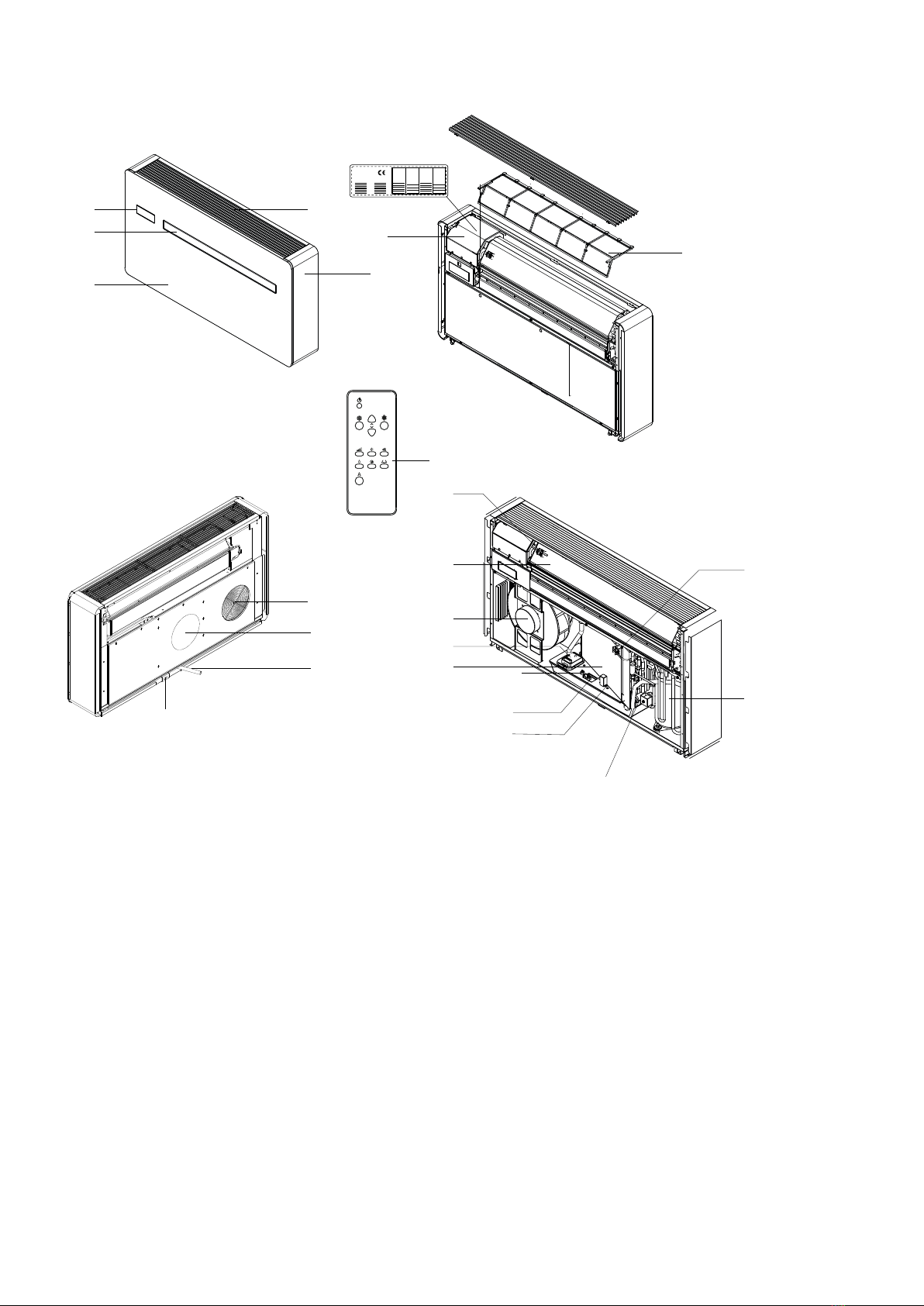
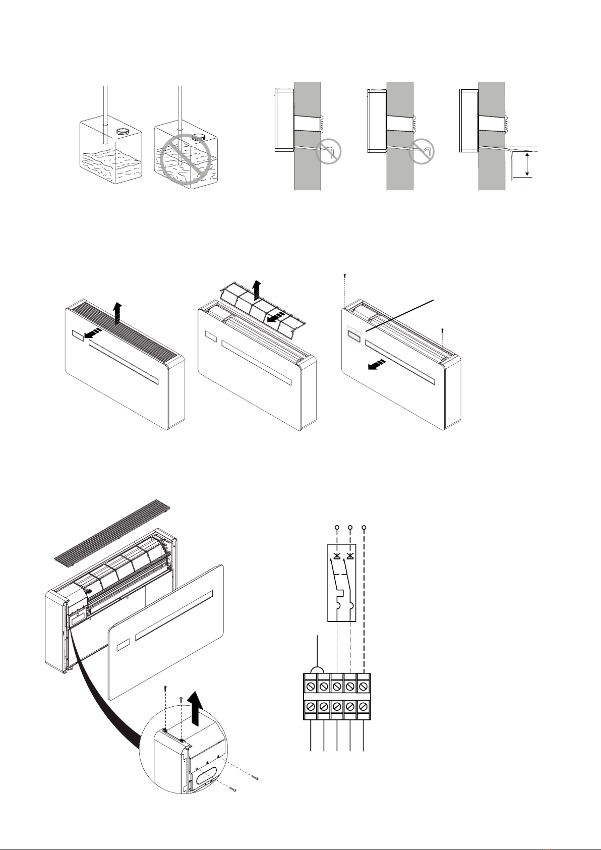
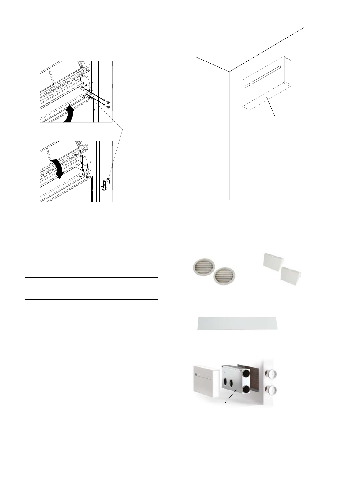
Frico Soloclim User manual

Soloclim
Original instructions
.... 11
EN .... 19
SE .... 10
NO .... 12
FR ....14
DE
....16
NL ....18
FI ....20
RU .... 22
PL .... 24
ES
....26
DK

SC21DCIN, SC23DCIN(1000)
SC17DCIN-MINI
1010
549
165
810
549
165
2
Soloclim
Introduktionssidorna består huvudsakligen av bilder. För översättning av de engelska texter
som används, se respektive språksidor.
SE
The introduction pages consist mainly of pictures. For translation of the English texts used, see
the respective language pages.
EN
Introduksjonssidene består hovedsakelig av bilder. For oversettelse av de engelske tekstene, se
de respektive språksidene
NO
Les pages de présentation contiennent principalement des images. Consulter la page
correspondant à la langue souhaitée.
FR
Die Einleitungsseiten bestehen hauptsächlich aus Bildern. Für die Übersetzung der
verwendeten Texte in englischer Sprache, siehe die entsprechenden Sprachseiten.
DE
Pocztkowe strony zawieraj gwnie rysunki. Tumaczenie wykorzystanych tekstw angielskich
znajduje si na odpowiednich stronach jzykowych.
PL
RU , .
R.
Esittelysivut koostuvat lähinnä kuvista. Suvuilla olevien enlanninkielisten sanojen käännökset
löytyvät ko. kielisivuilta.
FI
Introduktionssiderne består hovedsageligt af billeder. For oversættelse af de engelske tekster,
se siderne for de respektive sprog.
DK
De inleidende pagina's bevatten hoofdzakelijk afbeeldingen. Voor een vertaling van de
gebruikte Engelse teksten, zie de pagina's van de resp. taal.
NL
as pginas introductorias contienen bsicamente imgenes. Consulte la traduccin de los
textos en inglés que las acompañan en las páginas del idioma correspondiente.
ES

4
5
6
10
13
14
15
16
17 18
19
20
21
23
22
11 12
7
8
9
3
1
2
24
Fig.1 Components
3
Soloclim
1. Touch screen control panel
2. Air outlet deector
3. Front panel
4. Intake grille
5. Side panel
6. External air intake
7. External air outlet
8. Condensate drain tube 0,6 m
9. Anchor bracket
10.Data label
11.Terminal block
12.Air lter
13.Room temperature sensor
14.Internal exchanger
15.External fan
16.Condensation pump
17.External exchanger
18.Maximum level oat (not SC1DCI-MINI)
19.evel oat
20.Condensation drain valve
21.Four-way valve (not SC17DCI-MINI)
22.Compressor
23.Outdoor temperature sensor
24.Remote control

C
D
A++
A
I
F
E
B
J
G
A
H
A.Outside grilles for air inlet and outlet (2 pcs) Fig.6
B.Screws and plugs kit (6 pcs)
C.Wall mounting bracket
D.Manual
E. Remote control
Fig.2 Included in delivery
F. Paper drilling template Fig.4
G.CR2025 3V remote control battery
H. Plastic sheet for wall duct (2 pcs) Fig.5
I. Energy eciency label
J. Inside anges for air inlet and outlet ( pcs)
Fig.3 Minimum distances
max 2500
200
60
50
60 2000
4
Soloclim

B
C
F
IN OUT
DE
A
A.Holes for M8 plugs
B.Electrical connection area
C.Ø162 mm holes for air ducts
Fig.4 Drilling template
D.Ø18 mm condensate drain
E. Hole for anchor bracket
F. NOT USED
SC21DCIN, SC23DCIN(1000)
A
B
C
DE
IN OUT
5
Soloclim
SC17DCIN-MINI

A. Chain
B. Flange
C. Spring
D. Outside air grill
Fig.5 Air ducts
Fig.6 Wall grilles
IN OUT
IN OUT
IN OUT
A
B
C
D
Plastic sheets for air ducts
6
Soloclim

1
3
2
4
2
1. Spirit level
2. Wall bracket
3. Fixing screw
4. Expansion plug
5. Interlocking points
Fig.7 Mounting the unit
1
3
2
4
2
5
2
2
5
1. Drainage tube 0,6 m (Ø18 mm
outside, Ø13 mm inside)
2. Safety drain
Fig.8 Drainage
0 °
1° m a x .
1
2
7
Soloclim

1
2
1
1
22
Fig.10 Access to the terminal block
Fig.9 Opening the unit
A
B
grigio
grey
grigio / grey
grigio / grey
bLu / blue
giallo-verde / yellow-green
marrone / brown
3
23
1
Wiring diagram
GR Grey
BR Brown
YG Yellow-Green
BL Blue
CP Presence contact
N Neutral
L Phase
IG System main switch
PE Earth connection
I G
L
C P
G R
G R
G
R
B
R
B
L
Y
E - G N
NP E
30 0 m m
3%
Fig.8b Drainage
double sided
tape
8
Soloclim

Fig.11 High wall installation
A
B13
2
18 0 °
SCKEG162 SCRPK
SFSFH1
SCKL
Adjustment of deector
(changing air ow direction)
SCSFH1
180°
9
Soloclim
Accessories
Art. no Type WxHxD
[mm]
282045 SCKEG162 180x180x20
282046 SCRPK 230x120x170
990547 SCSFH1 940x15x155
999945 SCKL* 1006x505x165
999946 SCKR* 1006x505x165
*) See separate manual.

10
Soloclim
Technical specications
*4) Outdoor air temperature 35 °C, relative humidity 41%. Ambient temperature 27 °C; relative humidity 47%.
*5) Outdoor air temperature 7 °C; relative humidity 87%. Ambient temperature 20 °C; relative humidity 59%.
*6) Indoor sound pressure measured in semi-anechoic chamber at a distance of 2 m.
Max work conditions
Cooling temperature, (indoor/outdoor, Dry Bulb) ; minimum 18 °C/-5 °C, maximum 35 °C/43 °C
Heating temperature, (indoor/outdoor, Dry Bulb) ; minimum 5 °C/-10 °C, maximum 27 °C/24 °C
Energy classication according to the directive 626/2011
Energy eciency class cooling: A. (SC1DCI-MINI: A).
Energy eciency class heating: A.
Art. no Type Cooling
output*1
[kW]
Heat
output*1
[kW]
EER COP Voltage
[V]
Refrigerant
amount
[kg]
WxHxD
[mm]
Weight*2
[kg]
282044 SC17DCI-MINI 2,35 2,40 3,01 3,15 230V~ 0,14 (R290) 810x549x165 38
283421 SC21DCIN 2,64 2,64 3,29 3,31 230V~ 0,65 (R32) 1010x549x165 41
283422 SC23DCIN 3,10 3,05 3,25 3,28 230V~ 0,65 (R32) 1010x549x165 41
283423 SC23DCI1000N*33,10 ,00, 3,25 3,28 230V~ 0,65 (R32) 1010x549x165 41
SC17DCI-MINI SC21DCIN SC23DCIN SC23DCI1000N
Cooling*1
Max. cooling output Dual Power*4kW 2,35 2,64 3,10 3,10
Nominal cooling output*4kW 1,73 2,09 2,33 2,33
Min. cooling output*4kW 0,70 0,83 0,92 0,92
Dehumidication capacity l/24h 0,70 0,80 0,90 0,90
Total power consumption *4kW 0,57 0,64 0,72 0,72
Heating*1
Max. heat output Dual Power*5kW 2,40 2,64 3,05 3,95
Nominal heat output*5kW 1,71 2,08 2,31 2,31
Minimum heat output*5kW 0,75 0,71 0,79 0,79
Total power consumption*5kW 0,54 0,63 0,71 0,71
Max. breaking current A 3,90 4,10 4,60 8,50
Air ow at max fan speed in/out m³/h 360/430 380/460 400/480 400/480
Air ow at med fan speed in/out m³/h 300/360 310/380 320/390 350/390
Air ow at min fan speed in/out m³/h 240/320 260/330 270/340 270/340
Max/Min sound pressure*6dB(A) 39/27 39/26 41/27 41/27
*1) According to standard EN 14511
*2) Weight without refrigerant
*3) Equipped with an electric coil that provides an additional 900 W

Soloclim
11
EN
Installation and operating instructions
General Instructions
Read these instructions carefully prior to
installation and use. Keep this manual for future
reference.
The product may only be used as set out in the
assembly and operating instructions. The guarantee
is only valid should the product be used in the
manner intended and in accordance with the
instructions.
Application
Soloclim is a reversible airconditioner without outdoor
unit. Soloclim ensures a comfortable room temperature,
whether you want cooling or heating, at a reduced
consumption. Protection class: IPX0.
Soloclim horizontal is designed only for use with R32
gas as the designated refrigerant, with the exception
of SC17DCI-MINI which is designed only for use with
R290 (propane). Both are environmentally friendly
refrigerant gases, with low or negliable Global Warming
Potential (GWP). Special precautions must be taken into
consideration due to the ammability of the refrigerant.
This unit uses a ammable refrigerant. If
refrigerant leaks and comes in contact with re or
heating part, it will create harmful gas and there
is risk of re.
Only a qualied technician should attempt to
install and service the unit. Service personnel are
required to carefully read the user manual and
the safety manual "Repair and maintenance -
units with R290/R32/R410a" at www.frico.net.
Safety instructions
• This appliance can be used by children aged from 8
years and above and persons with reduced physical,
sensory or mental capabilities or lack of experience
and knowledge if they have been given supervision or
instruction concerning use of the appliance in a safe
way and understand the hazards involved. Children
shall not play with the appliance. Cleaning and user
maintenance shall not be made by children without
supervision.
• Children of less than 3 years should be kept away
unless continuously supervised.
• Children aged from 3 years and less than 8 years
shall only switch on/off the appliance provided
that it has been placed or installed in its intended
normal operating position and they have been given
supervision or instruction concerning use of the
appliance in a safe way and understand the hazards
involved.
• Children aged from 3 years and less than 8 years
shall not plug in, regulate and clean the appliance or
perform user maintenance.
• SC21/23DCI: The unit is designed only for use with R32
gas as the designated refrigerant.
• SC17DCI-MINI: The unit is designed only for use with
R290 (propane) gas as the designated refrigerant.
•The refrigerant loop is sealed. Only a qualied
technician should attempt to service.
• Do not discharge the refrigerant into the atmosphere.
It is ammable and heavier than air.
•The gas rst collects in low areas but can be circulated
by the fans.
• If gas is present or even suspected, do not allow
untrained personnel to attempt to nd the cause.
• The gas used in the unit has no odor. The lack of smell
does not indicate a lack of escaped gas.
• If a leak is detected, immediately evacuate all persons
from the premises, ventilate the premises and contact
the local re department to advise them that a gas leak
has occurred.
• Do not let any persons back into the premises until
the qualied service technician has arrived and that
technician advises that it is safe to return.
•No open ames, cigarettes or other possible sources of
ignition should be used inside or in the vicinity of the
units.
• After transport or if the unit has been tilted (e.g. during
cleaning), leave it for an hour before connecting it to
the mains supply.
• Always keep the unit in an upright position.
• Never use the plug to start and stop the unit. Always
use switch on the control panel.
•Do not use ammable cleaners on the unit.
• Never pour or spray water over the unit.
• Component parts are designed for the refrigerant and
non-incentive and non-sparking. Component parts shall
only be replaced with identical repair parts.
• If the supply cord is damaged, it must be replaced by
the manufacturer, its service agent or similarly qualied
persons in order to avoid a hazard.
• The unit shall be disconnected from its power source
during maintenance.
•Ensure the unit is far away from re, inammable,
or explosive objects.
• Do not use means to accelerate the defrosting process
or to clean, other than those recommended by the
manufacturer.
• The unit shall be installed and stored in a room without
continuously operation sources (for example: open
ames, an operating gas appliance or an operating
electric heater).
• The unit shall be installed and stored so as to prevent
mechanical damage from occurring. Do not pierce or
burn, even after use.
• SC17DCI-MINI: The unit shall be protected from
physical damage and shall be installed, operated and
stored in a room with a oor area larger than 4 m2.
• Compliance with national gas regulations shall be
observed.

A
B
C
D
Soloclim
12
EN
Mounting
Soloclim is designed for indoor installation on an exterior
wall. During all handling, the unit must be kept in upright
position. The unit is delivered with a drilling template for
the necessary mounting holes. Fig.4. The product must
be mounted in such a way to allow future service and
maintenance. For minimum distance, see diagrams on
introductory pages.
Drilling the air ducts Fig.4. Fig.5.
The drilled ducts must be straight and not longer than
1 meter. To prevent dust and debris in the room it is
recommended to couple the core drill to a vacuum
system. Proceed with caution in the vicinity of the outer
wall in order to avoid the breakage of plaster around the
hole. Take precautions so that the drilled material does
not fall on persons and objects below.
1. Position the drilling template and mark the positions of
the duct holes.
2. Use a drill to drill a pilot hole.
3. Use a core drill to drill the duct through the wall.
4. Keep a downward inclination toward the exterior.
Postioning the duct linings Fig.5.
1. Measure the depth of the ducts and substract 5 mm.
2. Cut the plastic sheets supplied to size.
3. Roll one plastic sheet and insert it into one of the ducts.
4. Position the sheet so that its edges are 2 mm inside
both ends of the duct.
5. Proceed the same way with the second sheet in the
second duct.
Postioning the outside wall grilles Fig.6.
Identify the two different external wall grilles by their
labels:
IN: air inlet wall grille
OUT: air outlet wall grille
1. Check the template to identify the outlet duct.
2. Fold the outlet wall grille.
3. Insert it through the duct to the other side of the wall.
4. Hold the chains with the other hand to prevent the
grille from falling.
5. Open the grille on the outside.
6. Rotate the grille so that the ns are in vertical position.
7. Insert the ange in the indoor hole.
8. Rotate it so that the hooks are in vertical position.
9. Pull the chains to keep the springs taut.
10. Hook the chains to the ange and cut off the excess.
11. Proceed the same way for the inlet wall grille.
When painting the grilles, use water-based paints suitable
for plastic surfaces to avoid problems with the movement
of the ns. Wall grilles with xed ns are available as
accessory.
Mounting the unit Fig.7.
The bracket must be xed on a level wall surface that
is capable of supporting the weight of the unit. An
inclination of maximum 1° towards the right side of the
unit is allowed to facilitate the drainage of condensate.
1. Use a spirit level when placing the drilling template on
the wall to ensure it is horizontal.
2. Mark the positions of the xing holes and drill the
holes.
3. Fix the bracket with the screws and the wall plugs.
4. Check that the installation is horizontal using the spirit
level.
5. Verify that predispositions for the electrical connection
and for the drainage have been made.
6. Fasten the unit to the upper part of the bracket.
• Keep any required ventilation openings clear of
obstruction.
• Keep the areas around the air intake and exhaust grilles
free from possible obstructions!
• The unit shall be protected from physical damage.
• Do not modify or tamper with the unit as this can lead
to danger.
•Do not leave the room closed for long. Periodically open
the windows to ensure proper ventilation.
• During the installation, it is necessary to observe
the precautions mentioned in this manual, as well
as to adopt any precaution suggested by the Safety
Regulations in force in the place of installation.
Warning
• Failure to abide by this warning could result in an
explosion, death, injury and property damage.
• Any person who is involved with working on or
breaking into a refrigerant circuit should hold a current
valid certicate from an industry-accredited assessment
authority, which authorizes their competence to handle
refrigerants safely in accordance with an industry,
recognized assessment specication.
• Repair and maintenance shall only be performed
as recommended by the manufacturer.
Maintenance and repair shall be carried out
according to the safety manual ”Repair and
maintenance - units with R290/R32/R410a” at
www.frico.net.
dentication of the unit
The unit can be identied by its data label. See g.1
"Components".
• According to EU Regulation No. 517/2014 concerning
certain uorinated greenhouse gases, it is mandatory
to indicate the total amount of refrigerant present in
the installed system. This information can be found on
the data label of the unit.
• Tampering with, removal of, or lack of data labels will
not allow for the safe identication of the product by its
serial number and therefore invalidates the warranty.

Soloclim
13
EN
Electrical installation
Soloclim is equipped with a 1,5 metre long cord with plug
for connection to an earthed power socket. The power
supply should be protected by a circuit breaker 1P+N,
6A, type C. If the cable is damaged it must be replaced
by a qualied service technician. The installation, which
should be preceded by an isolator switch with a contact
separation of at least 3 mm, should only be wired by a
competent electrician and in accordance with the latest
edition of IEE wiring regulations.
pening the unit ig
The unit shold not be opened by any unauthorised
personnel. Opening the unit is only necessary for adapting
it to a high wall installation or to access the terminal block.
1. Switch off the power and disconnect the unit.
2. Remove the upper grill by lifting it straight up starting
with the front edge.
3. Remove the lter by pulling it slightly towards the front,
then lifting it straight up.
4. Unscrew the two screws securing the front panel and
remove the panel. Note! The display is protected by
double-sided tape on the inside of the front.
Drainage ig
The unit is supplied with a drip tray for collecting the
condensation which should be channelled to a suitable
place for drainage. The drip tray is tted with a 0,6 m long
drainage tube with a safety drain. Size and position are
shown on the drilling template and g.8.
1. Remove the nozzle from drainage tube, or replace the
tube with a longer drainage tube. Be careful not to
squeeze the tube.
2. The whole tube must be coated with anti-condensation
insulation indoors and in the wall.
3. Direct it towards a suitable location for drainage and
keep a downward slope of minimum 3%.
4. Insulate junction points.
If no external drainage is prepared, do not remove the
nozzle from the drainage tube. It is possible to empty
the drip tray using the safety drain. When the drip tray is
full, the unit will stop and error code "OF" appears on the
display. See trouble shooting.
Collecting condensation in a container Fig.8b.
If the condensation is channelled to a water tank, or
similar, it should not be hermetically sealed. Prevent the
end of the drainage tube from immerse in the water.
Open drain Fig.8b.
If the condensation is not collected, check that the
expelled water does not cause any damage or problems
to people or objects. The water could freeze if the outdoor
temperatures are below zero, thus creating a hazard. In
this case, appropriate barriers should be installed in order
to prevent people from approaching the area.
igh wall installation
The unit can be installed near the oor or higher up on
the wall. The factory setting is made for low installation,
with the air ow directed upwards. High wall installation
is recommended when the unit is to be used for cooling
only. The bottom plate SCSFH1 is necessary for high wall
installation (ordered separately).
Adjustment of deector (changing air ow direc-
tion) Fig.11.
1. Switch off the power and disconnect the unit.
2. Remove grille and front panel (see Opening the unit).
3. Position the bottom plate SCSFH1 and x with the
screws provided.
4. Remove the xing screws of the right support bracket
for the air deector.
5. Rotate the bracket 180°.
6. Reinstall the bracket.
7. Reassemble the front panel and grille.
8. Proceed with the settings on the control panel.
After adjusting the air deector direction, the
settings on the control panel must be changed.
9. Press the deector key on the display for 10 seconds.
10. The symbol "dn" appears (low wall) ashing.
11. Press the deector key again.
12. The symbol "uP" appears on the display (high wall).
13. Wait 2 seconds until the new setting is memorised.
For the unit to work properly, the settings on the control
panel must be changed each time the orientation of air
deector is changed.
7. Verify that the bracket ts securely into the interlocking
points on the unit.
8. Fix the anchor bracket to the wall.
For easier connections, a spacer can be used to keep the
lower part of the unit away from the wall.
Access to the terminal block Fig.10.
Access to the terminal block is only necessary when
replacing the wired cable or when using the CP presence
contact.
1. Switch off the power and disconnect the unit.
2. Remove grille and front panel (see Opening the unit).
3. Unscrew the screws of the terminal block cover and
remove it.
It is possible to remove the unit's cable with plug and
connect the power supply directly to the terminal block.
This is recommended for high wall installation.
4. Disconnect the power cord from the terminal block.
5. Connect the power supply, checking that it has
a suitable earth connection and dimensionning
(minimum cable area: 1,5 mm2). Minimum cable area
for SC23DCI1000N is 2,5 mm2.
CP presence contact connection Fig.10.
When the CP contact opens (very low voltage, connected
to a potential free contact) the unit switches to stand-by
mode and CP appears on the display. This contact enables
the connection of an external device such as: prescence
sensor, window opening contact, remote on/off, activation
badge. A double insulation cable should be used. The CP
contact should always be used for the SC23DCI1000N to
avoid overheating. See wiring diagrams.

Soloclim
14
EN
Control panel Remote control
On / off
Fan mode
Timer
Hotel function
Decrease / down
Increase / up
Setpoint
Air deector
Automatic comfort mode
Digital thermometer:
Red bars - heating mode, blue bars - cooling
mode
Cooling mode
Dehumidication mode
Heating mode
Comfort mode Night
Setpoint
When the unit is on, the set value is shown on
the display with three digits. The setpoint value
can be set between 16 and 31°C. The setpoint
must not be set too high or low, as this means
unnecessary energy consumption and reduced
comfort.
On / off
The unit can be switched off (standby) or on
with this button. The system is equipped with a
memory, which means that the settings will not
be lost when the unit is turned off or the power
is switched off. The button is used to switch on or
off, for short periods.
If the unit is to be switched off for a long time,
the main switch must be switched off and the
power cord pulled from the socket.
Automatic comfort mode
The unit selects cooling or heating mode
automatically depending on the set temperature
and its fan speed according to the room
temperature.
Setting cooling or heating mode
To deactivate the heating or the cooling mode do
as follows:
• Keep the A key on the touch-screen display
pressed for 10 seconds until HC (heating and
cooling) appears on the display.
• Press the A key for 1 second to switch to
cooling mode (CO).
• Press the A key again to switch back to heating
mode (HO).
• Wait for 3 seconds without touching anything
to memorise the setting.
Cooling mode
In this mode, the unit dehumidies and cools
the room. Use the up/down buttons to set the
temperature.
The desired temperature can be set between 16
and 31°C and, if this temperature is lower than
the room temperature, the compressor starts
after three minutes (maximum) and the unit
starts producing cool air, maintaining fan speed
even if the setpoint has been reached.
Control
Soloclim is controlled by the touch-screen control panel on the front of the unit or
by the supplied remote control.
Setting power

Soloclim
15
EN
Dehumidication mode
In this mode, the unit dehumidies the room.
Selecting this mode is useful during mid-seasons,
i.e. on rainy days when the temperature is
pleasant, but the humidity excessive. The unit
runs on low fan speed regardless of settings and
room temperature. It is normal for the unit to
have an intermittent operation.
Fan mode
In this mode, neither heating, cooling nor
dehumidication is done. It is possible to select
fan speed.
Heating mode
In this mode, the unit heats the room. Set
the desired temperature between 16 and
31°C by using the up/down buttons. If the
set temperature is higher than the room
temperature, the compressor starts after max.
three minutes for heating.
In this mode, automatic defrosting is made when
necessary and heating is deactived during the
process.
Comfort mode Night
Comfort mode Night can be selected when the
unit is in cooling or heating mode, to optimse
sound level, energy savings and comfort during
the night. The unit runs with the lowest fan
speed.
• In cooling mode: the set temperature
increases by 1°C after one hour and by a
further 1°C after two hours. After this, the
set temperature does not change again and
after a further six hours the unit switches to
standby mode.
• In heating mode: the set temperature
decreases by 1°C after one hour and by a
further 1°C after two hours. After this, the
set temperature does not change again and
after a further six hours the unit switches to
standby mode.
This function is not available in dehumidifying
mode, fan mode and comfort mode, and can
be cancelled at any time by pressing the button
again. If the timer function is activated at the
same time, the unit switches off when the set
time ends.
Brightness
The display brightness sensor can be disabled
(leaving the maximum brightness at all times) by
pressing the night button for 10 seconds. ”ds”
(disabled) or ”En” (enabled) will appear on the
display.
Air deector
This button sets the position of the air deector:
• continuous oscillation - the symbol is shown
on the display
• blocked position.
NOTE!: The mobile air director must never be
moved manually. In cooling and dehumidication
mode, it resets every 30 minutes to prevent the
formation of condensation.
Setting power
The unit has ve power settings - Minimum,
Medium, Maximum, Dual Power and Automatic -
selected by pressing this key sequentially. Higher
power gives better performance but a higher
sound level.
• The Dual ower function is available in
heating and cooling mode and supplies a
90-minute overboost. The unit is then switched
to automatic mode. During the following 30
minutes the Dual Power function cannot be
selected. The Dual Power function is shown
by three ashing speed bars on the display
and the seven red or blue bars moving up and
down of the digital thermometer.
• In Automatic mode the unit automatically
adjusts the speed. The speed is higher
when the difference between the room
temperature and the setpoint is greater, and
then decreases automatically when the room
temperature approaches the setpoint. This
mode is not available in dehumidication
mode or comfort mode night. The Automatic
mode is shown by three speed bars moving up
and down on the display.
Timer
The unit can be programmed when to start or
stop by using the timer.
• When the unit is switched on, program
the timer to switch off the unit by pressing
the Timer button, followed by the number
of hours (from 1 to 24). Use the up/down
buttons. The unit will switch to standby mode
at the set time.
• When the unit is switched off, program
the timer to switch on the unit by pressing
the Timer button, followed by the number
of hours (from 1 to 24). Use the up/down
buttons. The unit will start at the set time.
Press the Timer button to conrm.
Child lock
The key lock is activated by keeping the Timer
symbol on the touch-screen display pressed
for three seconds. All actions are locked to the
user. The standby symbol ashes every second.
To deactivate the lock, keep the Timer symbol
pressed for three seconds once again.
The lock remains active in the case of a power
failure and also if the remote control is used.
Hotel function
The hotel function disables the dehumidication
mode and Auto functions, leaving cooling,
heating and fan modes active. The setting ranges
are reduced from 22 to 28°C in cooling mode and
from 16 to 24°C in heating mode.
Press the air exchange key for 10 seconds to
enable the function (”En” is shown).

Soloclim
16
EN
SC23DCI1000 operation
SC23DCI1000 has an additional electric coli of 900 W, used
in Heating mode.
The extra output is activated when the room
temperature is 24°C or below and minimum 2°C lower
than the set temperature. When the room temperature
reaches the setpoint (and is above 25°C) the electrical coil
function is blocked. It will also be blocked if the fan stops
or if there is a problem with the compressor.
In Comfort mode Night, the compressor is not used and
the extra output is activated when the room temperature
is 27°C or below and minimum 1°C lower than the set
temperature.
N.B.To avoid internal overheating, it is forbidden to
suddenly cut the power to the SC23DCI1000! Use the
CP contact which puts the unit in standby mode and
guarantees correct post-ventilation. Never cover the air
inlet and outlet!
Suggestions for saving energy
•Always keep the lters clean.
• Keep doors and windows closed in the air conditioned
room.
• Do not let direct sunlight enter the room (use curtains,
blinds or shutters).
• Avoid using high energy consumption devices in the
room.
Maintenance
The power supply to the unit must be disconnected during
all service, repair and maintenance work. Wait until the
unit is cold.
Housing
To clean the casing, wipe it with a soft, dry cloth. If it is
very dirty, use a slightly damp cloth and, if necessary,
a mild detergent. Wipe afterwards with a dry cloth to
remove moisture.
Filter
Clean the air lter after a period of continuous use and
according to the concentration of impurities in the air,
or when you wish to start-up the unit after a period of
inactivity.
1. Extract the lter, see Opening the unit.
2. Clean the lter with a vacuum cleaner or by washing it
in running water.
3. Allow it to dry completely before putting it back in the
unit.
Remote control
The remote control has a working range of approximately
8 metres. Its top must point towards the display of the
unit. The reception of the command is conrmed by a
beep and by the display.
• Insert the supplied battery in the remote control before
operation.
• Remove batteries when not in use for an extended
period in order to preserve battery life.
• Always use the same type of batteries when changing
them.
Packaging
Packaging materials are chosen with consideration to the
environment and are therefore recyclable.
andling of product at end of woring life
This product may contain substances necessary for the
functionality of the product but potentially dangerous for
the environment. The product should not be disposed of
mixed with general household waste but delivered to a
designated collection point for environmental recycling.
Please contact the local authority for further details of
your nearest designated collection point.

Soloclim
17
EN
Trouleshooting
ActionCause
Symptom
The unit does not work.
The power is not connected.
Insert the plug into the wall outlet and push the ON button.
The lter is clogged. Clean the lter.
Make sure the air inlet and outlet are not obstructed.
The air does not pass freely through
the unit.
If the fault cannot be rectied, please contact a qualied service technician.
There is too much ventilation. Reduce ventilation, close doors and windows.
Check and, if necessary, adjust the temperature settings.The desired temperature is set too
high or too low.
The cooling or
heating capacity is not
adequate.
The heating and/or cooling load has
increased.
Cover large windows exposed to sunlight. Avoid using halogen
lamps or other high energy consumption devices.
Use the control panel on the unit.The remote control does not work.
The remote control
does not work. The remote control is not aimed at the
unit's remote control receiver.
The distance between the unit and the
remote control is too large.
The batteries are dead.
Make sure that the remote control is close enough to the unit
and is pointing towards the receiver.
Change batteries.
See next page.An error code is displayed.
Check that the system main switch has not been tripped (if it
has, reset it). If the problem repeats immediately, contact Frico
Technical support and do not try to make the unit work.
Check there is power supply (by turning a light on, for
example).

E1
E2
E3
E4
E5
E6
E7
E8
CP
OF
Soloclim
18
EN
Cause
Error code
Contact lost with control panel
Outdoor temperature sensor fault
Operating modes
Maximum oat level reached.
Should any anomaly occur in the condensation water
system, the level oat will stop the unit and the error code
"OF" appears on the display.
During cooling and dehumidication, electronics keeps
the water distribution system active in the coil - together
with the fan - to disperse excess water in the drip tray. If
the problem persists, please contact the Frico technical
support.
When in operation, condensation should drain freely
through the designated tube. In the event of an alarm,
check that the tube is not bent or obstructed, thus
preventing the water from owing out.
Cooling, Dehumidication and Heating modes can still be
activated. It only monitors the antifreeze function of the
internal coil.
Cooling, Dehumidication and Heating modes can still be
activated.
Cooling, Dehumidication and Heating modes can still be
activated. Defrosting is performed at xed times.
None of the modes can be activated.
The unit only works if the contact is closed. Check the
connections. See ”CP presence contact”.
Open CP presence contact.
External coil sensor fault
Internal coil sensor fault
Room temperature sensor fault
Internal fan motor fault
External fan motor fault
If the fault cannot be rectied, please contact Frico Technical support specifying the error code to simplify intervention.
Compressor discharge fault

Main o ce
Frico AB Tel: +46 31 336 86 00
Industrivägen 41
Sweden www.frico.net
or latest updated information and information
aout your local contact wwwfriconet
2022-07-20 CH
Table of contents
Other Frico Air Conditioner manuals

Frico
Frico AR200 Series User manual

Frico
Frico AR3200C User manual

Frico
Frico AR3500E User manual

Frico
Frico Sunnan SUN12 User manual

Frico
Frico PA1006 User manual

Frico
Frico TKW20 User manual

Frico
Frico AD200A User manual

Frico
Frico Thermozone AC 300 User manual

Frico
Frico Thermozone PA2200C User manual

Frico
Frico Thermozone PA3500 User manual

Frico
Frico Soloclim SCV21DCIN User manual

Frico
Frico AGS5500 User manual

Frico
Frico AD100 User manual

Frico
Frico PA2500 User manual

Frico
Frico AR3500 Series User manual

Frico
Frico PA34WB15 User manual

Frico
Frico TKW40 User manual

Frico
Frico PA2500 User manual

Frico
Frico AGI6000 User manual

Frico
Frico Thermozone AD310W User manual