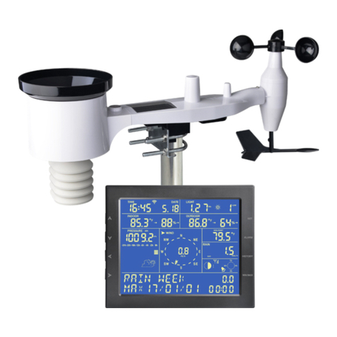
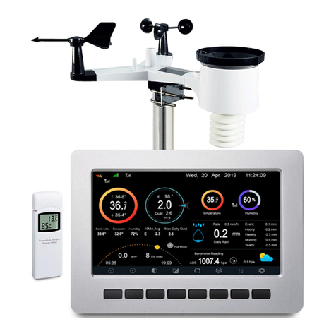
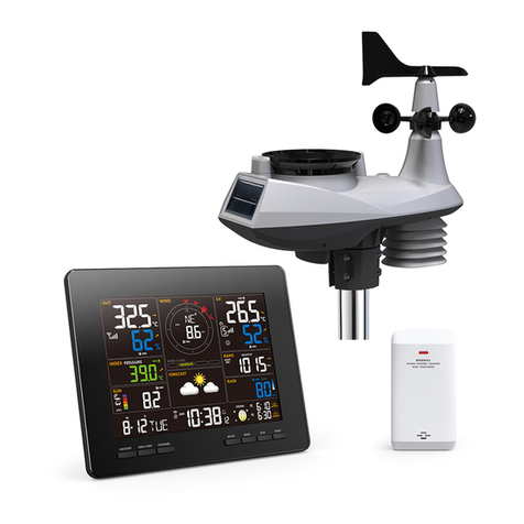
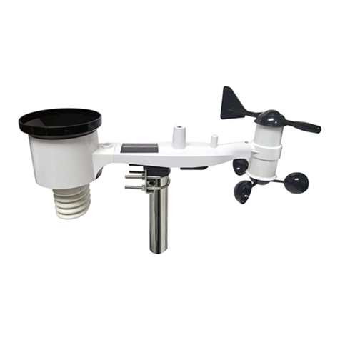
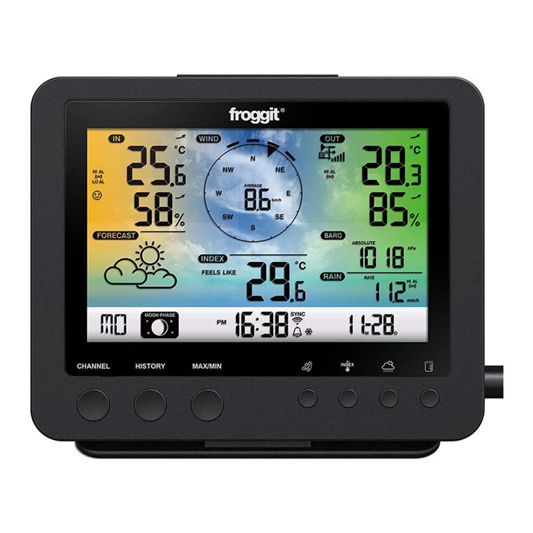
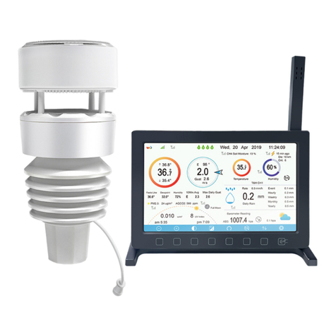
Froggit DP2000 User manual

1
DP2000
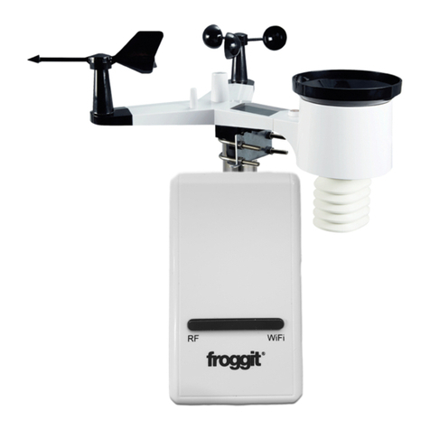
7-In-1 Ultra WiFi Internet Wireless
Weather Station
Manual EN
Support/updates/manuals/spare parts:
www.froggit.de

2
The following optional sensors (purchased separately
) can be used with
DP2000 console display.
If you have purchase e tra sensors, just simple
power up, the display
console will receives the data automatically. If
sensor not reporting
in to console, the display console will re-
search the data after one
hour or restart the console to search the data.
Please refer to the
sensor manual (provided separately with sensor)
for details.
This table shows the maximum number of each type of
sensor
worked with console display
Sensor Image
DP 0 Multi-channel temperature and
humidity sensor
DP100 Soil moisture sensor
DP200 PM2. air quality sensor
DP70 Water leak alarm
DP60 Thunder and lightning
) can be used with
power up, the display
sensor not reporting
search the data after one
Please refer to the
for details.
sensor
that can be
Maximum
Number
8
8
1
4
1

3
DP2 0 Indoor PM2. /PM10 CO2 air
quality sensor temperature/humidty
DP10 Leaf wetness sensor
* the data won’t be displayed on the main
screen, it will show its data on the
Channel Data page.
Sensor Image
DP3 stainless-steel probe thermometer
for soil and water
DP1 0 wire probe thermometer for water
DP3 and DP1 0 share the 8 channels
1
8
Maximum
Number
8

4
Table of Contents
1 TABLE OF CONTENTS ..................................................................................... 4
UNPACKING ........................................................................................................ 5
3 OVERVIEW .......................................................................................................... 5
4 SENSOR ARRAY SET UP .................................................................................. 8
4.1
I
NSTALL BATTERIES
.......................................................................................... 8
4.2.
M
OUNTING
...................................................................................................... 8
4.3
R
ESET
B
UTTON AND
T
RANSMITTER
LED ....................................................... 11
4.4.
C
ALIBRATION
................................................................................................ 11
4.
S
ITE
S
URVEY
.................................................................................................. 11
4.6
B
EST
P
RACTICES FOR
W
IRELESS
C
OMMUNICATION
....................................... 12
5 WI-FI CONFIGURATION ................................................................................ 13
.1
B
EFORE
S
ETUP
............................................................................................... 13
.2
S
ETUP
M
ETHOD
.............................................................................................. 13
.2.1 Method A: Setup via app ........................................................................ 13
.2.2 Method B: Setup via Embedded Webpage ............................................. 1
.3
R
EGISTERING
E
COWITT
W
EATHER
S
ERVER
.................................................... 19
.3.1 Viewing data on ecowitt.net ................................................................... 20
.4
R
EGISTERING
W
EATHER
U
NDERGOUND
......................................................... 23
.4.1 Viewing data on wunderground.com ..................................................... 27
.
R
EGISTERING
W
EATHER
C
LOUD
..................................................................... 30
.6
W
EATHER
O
BSERVATIONS
W
EBSITE
(WOW) ................................................ 31
.7
E
MBEDDED
W
EBPAGE OTHER FUNCITONS
...................................................... 3
2.
L
IVE
D
ATE
........................................................................................................ 36
6 MAINTENANCE ................................................................................................ 41
7 TROUBLESHOOTING GUIDE ....................................................................... 44
8 SPECIFICATIONS............................................................................................. 47
5
Unpacking
Open your weather station box and inspect that the contents are intact
(nothing broken) and complete (nothing missing). Inside you should find the
following:
QT
Y
Item Description
1
Wi
-
Fi
/LAN
Gateway
1
7
-
in
-
1 Sensor Array
with built
-
in: Thermo
-
hygrometer / Rain
Gauge / Wind Speed Sensor/ Wind Direction Sensor/UV/Light
sensor, Solar panel
1
White O
-
ring
1
USB to 2. *0.7mm DC V power plug connector cable
1
Ethernet
Cable
1
User manual (this manual)
Table 1: Package content
If any component is missing from the package, or broken, please contact our
Customer Service department to resolve the issue.
Overview
WiFi/Lan Gateway
Figure 1: Wi-Fi Gateway

6
Ref. LED Description
1 Sensor Link
(blue)
On: flash when one packet of wireless sensor data
was received
Off: No wireless sensor data is received. Please
check whether the wireless sensor is working
normally, and make sure that the sensor can
connect to the device hotspot
"GW2000-WIFIXXXX" with a mobile phone/PC,
open the browser, and log in to the webpage
192.168. 4.1 (the initial password is empty), enter
the Sensors ID interface to re-register the
corresponding wireless Sensor .
2 Server (red) On (steady): network communication normal and data
uploaded to configured weather service(s)
successfully.
Flash (faster): Wi-Fi configuration mode is active.
Use the WS View Plus app to complete the con-
figuration.
Flash (slow): network communication normal, but
upload to one or more configured weather services
failed. First confirm Internet access through your
router is functioning, and then check whether the
upload server account and password are correct (use
WS View application).
Off : Wi-Fi connection failed
Table : LED Indicators

7
7-in-1 Sensor Array
Figure : Wireless Sensor Array
1. Solar Panel 7. Haptic Rainfall sensor
2. Ultrasonic wind sensor 8. NORTH alignment indicator
3. Temperature & humidity sensor 9. Battery compartment
4. Fixed Bolt (Mounting on a pole
with 1 inch diameter)
10. Heating power cable connector
. USB port (Factory use only) 11. Reset button
6. Light & UV sensor, LED indicator 12.Calibration button (factory use
only )
Table 3: Sensor assembly detailed items

8
Sensor Array Set up
4.1 Install batteries
Insert 2XAA batteries in the battery compartment. The LED indicator(on
the top of the sensor) will turn on for 3 seconds and normally flash once
every 8.8 seconds (the sensor transmission update period).
Note: If no LED light up or is lighted permanently, make sure the
battery is inserted the correct way or a proper reset is happened. Do not
install the batteries backwards. You can permanently damage the
outdoor sensor
Figure 3: Battery installation diagram
Note: We recommend lithium batteries for cold weather climates, but
alkaline batteries are sufficient for most climates. We do not recommend
rechargeable batteries. They have lower voltages, do not operate well at
wide temperature ranges, and do not last as long, resulting in poorer
reception.
4. . Mounting

9
Before you mount
Before installing your outdoor sensor in the permanent location, we
recommend operating the device for one week in a temporary location with
easy access. This will allow you to check out all of the functions, insure
proper operation and familiarize you with the weather station and calibration
procedures.
1. Mounting on a pole with 1 inch diameter as Figure 4. Make sure the
mounting pole is vertical, or very close to it. Use a level as needed
Figure 4 installation diagram
Note: Make sure the mounting tube for the sensor package is installed
vertically (use a level at 90-degree offsets around the tube). Adjust the
mounting pipe as necessary..
2.
T
here is an arrow icon with”N” words (Figure ) representing the
direction of North. The sensor body has to be adjusted so that the “N”
indication is facing to real north direction in your location. A compass
device is recommended to help adjust direction. Permanent wind
direction error will be introduced when the outdoor sensor is not installed
in right direction.

10
Figure 5 Facing North diagram
Note: In Southern hemisphere, it is not necessary to change the
orientation to SOUTH as its solar panel is a rounded type and it is
orientation free for its charging capability.
3. During wintertime, to prevent ice formed on the reflection surface, the
optional extension cord be connected to a 12v/1.0A outdoor type power
adapter as Figure 6 showed below.
After power by the adaptor, the built-in thermostat heating plate will
automatically turns on below °C (40°F) and automatically turns off
above 10°C ( 0°F), the heat plate will melts snow and ice and keeps its
anemometer working as usual.
Note: The outdoor rated adapter and extended power cable can be
purchased separately:
Accessory Part only, not included!

11
Figure 6: Sensor package mounting diagram
4.3 Reset Button and Transmitter LED
In the event the sensor package is not transmitting, reset the sensor.
Press the RESET button ,the top LED light will be on for three seconds, then
resume as normal, flashing approximately once every 8.8 seconds.
4.4. Calibration
The ultrasonic sensor has been calibration before leaving the factory. We do
not recommend that customers do calibration by themselves.
Customers use this feature only when the wind speed does not return to zero
when there is no wind
After the product works normally, use a cloth or sponge with good water
absorption (prevent the echo of the ultrasonic waves) to completely wrap the
air inlet.
Press and hold the CAL button for three seconds, the top LED light will be on.
After releasing the CAL button, place the product on the table. After five
seconds, the top LED light will flash. At this time it is in the calibration mode.
Wait for the LED to flash, the calibration is over, and the product
automatically enters the normal working mode.
4.5 Site Survey
Perform a site survey before installing the weather station. Consider the
following:
Ideally mounted at 32.8 feet (10 meters) above ground level.
Try to make the anemometer the highest object around. 7 feet (2.76
meters) or more above the surrounding obstructions is best.

12
Best Practices for Wireless Communication
Wireless (RF) communication is susceptible to interference, distance, walls
and metal barriers. We recommend the following best practices for trouble
free wireless communication between both outdoor sensors and the gateway:
Electro-Magnetic Interference (EMI). Keep the gateway several feet away
from computer monitors and TVs.
Radio Frequency Interference (RFI). If you have other devices operating
on the same frequency band as your indoor and/or outdoor sensors and
experience intermittent communication between outdoor sensors and
gateway, try turning off these other devices for troubleshooting purposes.
You may need to relocate the transmitters or receivers to avoid the
interference and establish reliable communication.
Line of Sight Rating. This device is rated at 100 meter line of sight (under
ideal circumstances; no interference, barriers or walls), but in most
real-world scenarios, including a wall or two, you will be able to go about
30 meter
Metal Barriers. Radio frequency will not pass through metal barriers such as
aluminum siding or metal wall framing. If you have such metal barriers
and experience communication problems, you must change the placement
of outdoor sensors and gateway.
The following table shows different transmission media and expected signal
strength reductions. Each “wall” or obstruction decreases the transmission
range by the factor shown below.
Medium RF Signal Strength Reduction
Glass (untreated) -1 %
Plastics 10-1 %
Wood 10-40%
Brick 10-40%
Concrete 40-80%
Metal 90-100%
Table 4: RF Signal Strength reduction

13
Wi-Fi Configuration
5.1 Before Setup
Connect the Gateway console power jack to AC power with the power
adapter (included).
When powered up the Gateway, the Sever LED will flashes quickly. It means
that the gateway is in the Wi-Fi configuration mode. If it does not flash
quickly, press and hold the top RESET button for S to enter the Wi-Fi
configuration state
The Gateway console can connect to your network via Wi-Fi or directly
connected to your router using the included Ethernet cable.
Place the powered sensors array about 2 to 3 meter from the Gateway console
receiver and wait several minutes for the remote sensors to synchronize with
the receiver.
5. Setup Method
5. .1 Method A: Setup via app
Install WS View Plus app. Then follow up the instruction as the App will
walk you through the SETUP Process
Remark: We recommend method A to be used in the first place. Please follow
the App’s instruction to complete account registration and device provision. If
method A is not working for you, please follow method B to start

14
ECOWITT Dashboard vs WU Dashboard vs Live Data
Here is a short explanation showing data difference:
Live Data is obtained by the mobile app by conn
ecting directly to the
gateway. This can only happen when your mobile device and gateway are
connected to the same Wi-
Fi network. It will then show up after you select
“Device List” from the main settings menu. If your mobile device is in
another network,
no device(s) will show up in this list and you will not be
able to select a device for displaying the “Live Data” screen.
ecting directly to the
gateway. This can only happen when your mobile device and gateway are
Fi network. It will then show up after you select
“Device List” from the main settings menu. If your mobile device is in
no device(s) will show up in this list and you will not be

15
ECOWITT Dashboard shows the data obtained from
ECOWITT
This requires that your mobile device can reach the Internet and theref
this is possible even when you are not on your home Wi-
Fi network, such as
when using cellular data.
WU Dashboard
shows the data obtained from WU server. This requires
that your mobile device can reach the Internet and therefore this is possible
even when you are not on your home Wi-
Fi network, such as when using
cellular data.
5. . Method B: Setup via Embedded Webpage
1. Find the Gateway GW2000X-WIFIXXXX
from your device
(computer, smart phone, or tablet with a browser)
as Figure 7
Or
Plug in Ethernet cable to connect this
gateway to WiFi router, find its’
assigned IP address via DHCP
2. O
pen a browser, navigate to the following IP address 192.168.4.1
Figure 8
Figure 7 Figure 8
ECOWITT
server.
This requires that your mobile device can reach the Internet and theref
ore
Fi network, such as
shows the data obtained from WU server. This requires
that your mobile device can reach the Internet and therefore this is possible
Fi network, such as when using
from your device
as Figure 7
gateway to WiFi router, find its’
pen a browser, navigate to the following IP address 192.168.4.1
as

16
After Apply, check
whether the IP address
is
3. Enter Login web page as Figure 10.
There is no need to enter the password when you are login for the first
time. Press Login button to enter webpage interface.
Figure 10 Login screen
4. Local Network
Upload data to the weather services, start from here, complete below
steps.
After Apply, check
whether the IP address
is
retrieved
There is no need to enter the password when you are login for the first
Upload data to the weather services, start from here, complete below
I to III
I
II
III

17
Mark this MAC, which you
will use to add device on the
Ecowitt Weather service
Set the reporting interval
time (default: 1 minute).
.Weather Services
Finished Registration in the weather server you want to upload the data and
get the Station ID and Password in the weather Server. Enter it in the below
“Weather Server” screen.
Figure 13 Weather Server screen

18
The supported services are shown in the table below:
Hosting
Service
Website Description
Ecowitt
Weather
https://www.ecowitt.net Ecowitt is a new weather server
that can host a bunch of sensors
that other services don’t support.
Weather
Undergound
https://www.wundergrou
nd.com
Weather Underground is a free
weather hosting service that allows
you to send and view your weather
station data real-time, view graphs
and gauges, import text data for
more detailed analysis and use
iPhone, iPad and Android
applications available at
Wunderground.com. Weather
Underground is a subsidiary of The
Weather Channel and IBM.
Weather
Cloud
https://weathercloud.net Weathercloud is a real-time
weather social network formed by
observers from around the world.
Weather
Observation
Website
(WOW)
http://wow.metoffice.gov
.uk/
WOW is a UK based weather
observation website. WOW allows
anyone to submit their own weather
data, anywhere in the world.
Customized
Website
Supports uploading to your
customized website, if the website
has the same protocol with
Wunderground or Ecowitt
Table 4: Supported Weather Servers

19
5.3 Registering Ecowitt Weather Server
It’s recommended to use the Ecowitt Weather server to monitor and record
your sensors’ data.
To register with Ecowitt follow these steps:
1) On the Weather Server page,
set the reporting interval time
minute).
2) Visit the website: https://www.ecowit
t.net on your computer and finish
the registration on the page.
Press the upper left menu button and select Devices.
Press Add Device and input all the information needed
address can be found on the Weather Server page).
Press Save.
Press
Dashboard on the menu. Your sensor data would be available on
the dashboard within several minutes.
Note: When select device address on map, please wait till the map display
before select your address.
Note: Please put in the correc
t time zone to get the correct time. Because the
time will be updated to internet time automatically while WIFI connection.
It’s recommended to use the Ecowitt Weather server to monitor and record
set the reporting interval time
(default: 1
t.net on your computer and finish
Press Add Device and input all the information needed
(The MAC
Dashboard on the menu. Your sensor data would be available on
Note: When select device address on map, please wait till the map display
t time zone to get the correct time. Because the
time will be updated to internet time automatically while WIFI connection.

20
You may add a shortcut to the ecowitt.net website on the home page of your
phone so that you can visit it just like opening an app.
5.3.1 Viewing data on ecowitt.net
You can observe your sensor’s data by using the
ecowitt.net
will use a URL like this one, where your station ID replaces the text
“STATIONID”.
https://www.ecowitt.net/home/index?id=STATIONID
Note: If you w
ant to share your station data with other users, you’ll need to set
your data to be public. Other users need to log in the ecowitt.net first to view
your data.
It will show a page such as this, where you can look at today’s data and
historical data as well.
Dashboard
You may add a shortcut to the ecowitt.net website on the home page of your
ecowitt.net
web site. You
will use a URL like this one, where your station ID replaces the text
ant to share your station data with other users, you’ll need to set
your data to be public. Other users need to log in the ecowitt.net first to view
It will show a page such as this, where you can look at today’s data and
Other manuals for DP2000
1
Table of contents
Other Froggit Weather Station manuals

Froggit
Froggit WH2600 PRO User manual

Froggit
Froggit WH6000 User manual

Froggit
Froggit HP1000SE User manual

Froggit
Froggit WH5500 User manual

Froggit
Froggit WH3000 User manual

Froggit
Froggit WH1080SE User manual

Froggit
Froggit WH3000SE Installation manual

Froggit
Froggit WH2800 User manual

Froggit
Froggit WH6000 PRO User manual

Froggit
Froggit WH3000SE User manual