Froggit WH2600 PRO User manual

1
WH2600 PRO Wi-Fi Weather Station
with APPs
Operation Manual
1. Introduction ................................................................................................
................................
2. Warnings and Cautions ................................................................
................................
3. Quick Start Guide ................................................................................................
................................
4.Pre-Installation Checkout and Site Survey ................................................................
................................
4.1 Pre Installation Checkout ................................................................
................................
4.2 Site Survey ................................................................................................
................................
. Getting Started ................................................................................................
................................
.1 Parts List ................................................................................................
................................
.2 Sensor Set Up ................................................................................................
................................
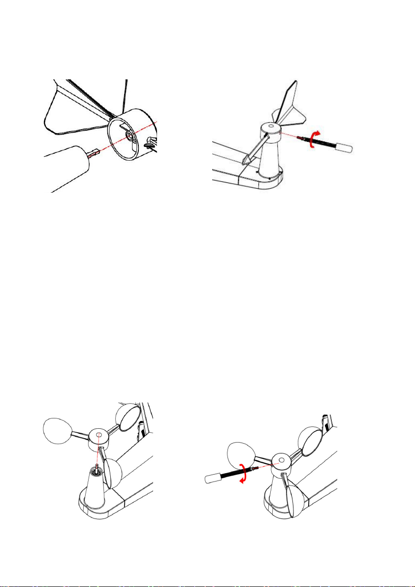
.2.1 Install wind vane ................................................................
................................
.2.2 Install wind speed ................................................................
................................
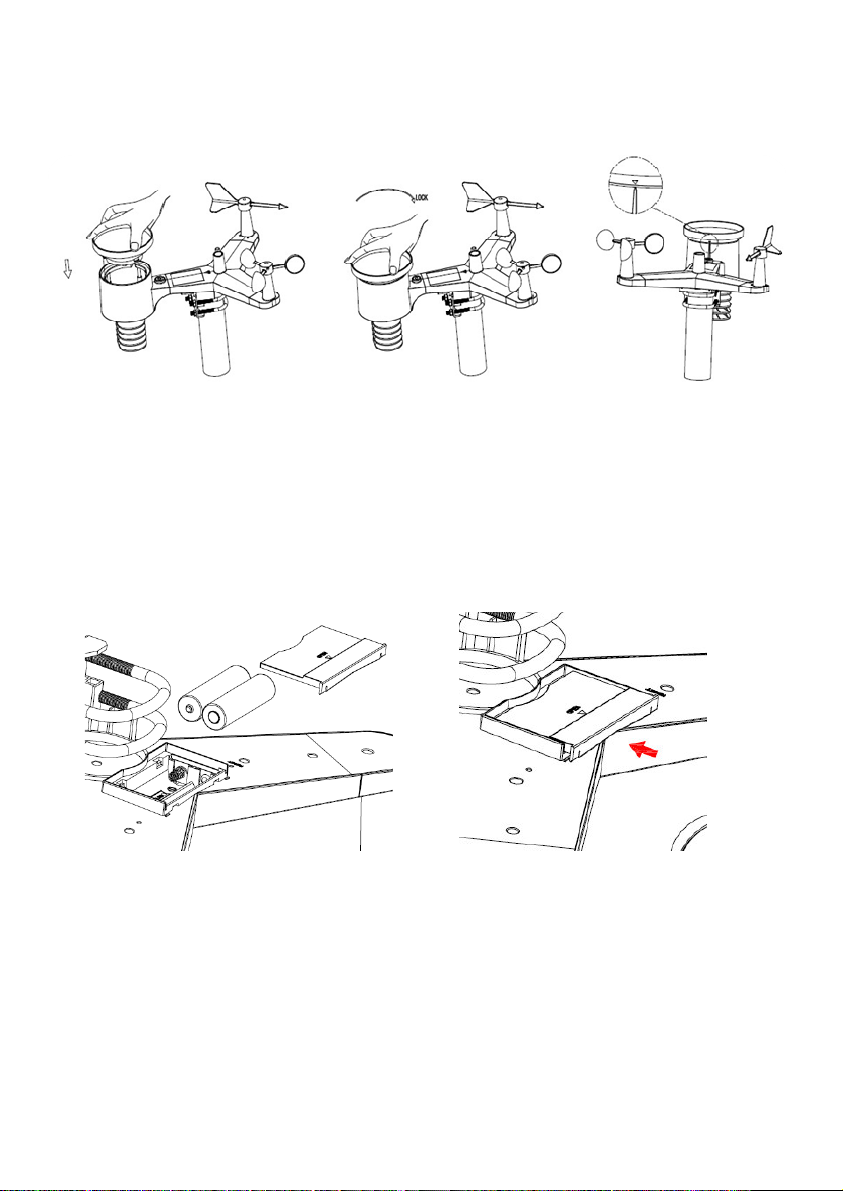
.2.3 Install Batteries ................................................................
................................
.2.4 Mount outdoor sensor .........................................................................
Fehler! Textmar e nicht definiert.
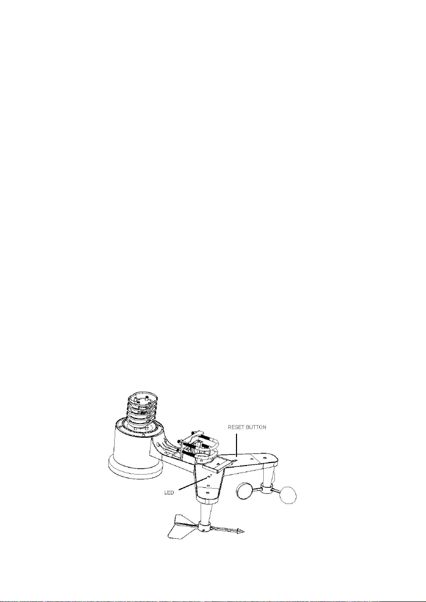
.2. Reset Button and Transmitter LED ................................
................................
.3 Indoor Thermo-Hygrometer-Barometer Transmitter ................................
................................
.4 Best Practices for Wireless Communication ................................
................................
. Receiver ................................................................................................
................................
. .1 Hardware Requirements ................................................................
................................
. .2 APPs - WS View ................................................................
................................
. .3 Connections ................................................................................................
6. WIFI connection setting on mobile................................................................
................................
6.1 Weather server: .........................................................................................
Fehler! Textmar e nicht definiert.
6.2 How to get the WS View application on mobile device ................................
................................
6.3 How to create Weather server account and station ID ..............................
Fehler! Textmar e nicht definiert.
7. Glossary of Terms ................................................................................................
................................

2
8. Specification ................................................................................................
................................
1. Introduction
Thank you for your purchase of the WH2600 PRO weather station. The
following user guide pro ides step by step instructions for installation,
operation and troubleshooting.
2. Warnings and Cautions
Warning: Any metal object may attract a lightning strike, including
your weather station mounting pole. Ne er install the weather station in a
storm.
Warning: Installing your weather station in a high location may
result in injury or death. Perform as much of the initial check out and
operation on the ground and inside a building or home. Only install the
weather station on a clear, dry day.
3. Quick Start Guide
Although the manual is comprehensi e, much of the information contained
may be intuiti e. In addition, the manual does not flow properly because
the sections are organized by components.
The following Quick Start Guide pro ides only the necessary steps to
install, operate the weather station, and upload to the internet, along with
references to the pertinent sections.

3
Required
Step Description Section
1 Assemble and power up the sensor array 5.2
2 Power up the indoor
thermometer-hygrometer-barometer
5.3
3 Power up the gateway recei er, connect to your
router and synchronize with sensor array and
thermo-hygrometer-barometer.
5.5.4
4. Pre-Insta ation Checkout and Site Survey
4.1 Pre Insta ation Checkout
Before installing your weather station in the permanent location, we
recommend operating the weather station for one week in a temporary
location with easy access. This will allow you to check out all of the
functions, insure proper operation, and familiarize you with the weather
station and calibration procedures. This will also allow you to test the
wireless range of the weather station.
4.2 Site Survey
Perform a site sur ey before installing the weather station. Consider the
following:
1. You must clean the rain gauge e ery few months. Pro ide easy access
to the weather station.
2. A oid radiant heat transfer from buildings and structures. In general,
install the sensor array at least 5’ from any building, structure, ground,
or roof top.
3. A oid wind and rain obstructions. The rule of thumb is to install the
sensor array at least four times the distance of the height of the tallest
obstruction.

4
4. Wireless Range. The radio communication between gateway recei er
and transmitter in an open field can reach a distance of up to 100 meter,
pro iding there are no interfering obstacles such as buildings, trees,
ehicles, high oltage lines. Wireless signals will not penetrate metal
buildings.
5. Radio interference such as PCs, radios or TV sets can, in the worst
case, entirely cut off radio communication. Please take this into
consideration when choosing recei er or mounting locations. Make
sure your recei er is at least fi e feet away from any electronic de ice
to a oid interference.
5. Getting Started
5.1 Parts List
QTY Item
1 Gateway Recei er
1 Thermo-hygrometer-barometer transmitter
1 Y shape outdoor sensor( including 1xThermo-hygrometer /
1xRain Gauge / 1xTransmitter 1)
1 Wind Vane
1 Wind Speed Cups
1 Rain Funnel
1
Metal mounting plate with U-bolt
1 5V DC Adaptor
1 User manual

5
5.2 Outdoor Sensor Set Up
Figure 1: Sensor assemb y components
1 Wind ane 7 Solar panel
2 Wind speed cups 8 U-Bolts
3 Light sensor and UV sensor 9 Battery compartment door
4 Thermo- and hygro-meter senor 10 Reset button
5 Rain collector 11 LED (red) to indicate data
transmission
6 Bubble le el
5.2.1 Insta U-bo ts and meta p ate
Installation of the U-bolts, which are in turn used to mount the sensor
package on a pole, requires installation of an included metal plate to recei e
the U-bolt ends. The metal plate, isible in Figure 2, has four holes through
which the ends of the two U-Bolts will fit. The plate itself is inserted in a
groo e on the bottom of the unit (opposite side of solar panel). Note that one
side of the plate has a straight edge (which goes into the groo e), the other
side is bent at a 90-degree angle and has a cur ed profile (which will end up
“hugging” the mounting pole). Once the metal plate is inserted, remo e nuts
from the U-Bolts and insert both U-bolts through the respecti e holes of the
metal plate as shown in Figure 2

6
Figure 2: U-Bo t insta ation
Loosely screw on the nuts on the ends of the U-bolts. You will tighten these
later during final mounting. Final assembly is shown in Figure 3.
Figure 3: U-Bo ts and nuts insta ed
The plate and U-Bolts are not yet needed at this stage but doing this now may
help a oid damaging wind ane and wind speed cups later on.
5.2.2 Insta wind vane
Push the wind ane onto the shaft on the top side of the sensor package, until
it goes no further, as shown in Figure 4. Next, tighten the set screw, with a
Philips screwdri er (size PH0), as shown on the right side, until the wind
ane cannot be remo ed from the axle. Make sure the wind ane can rotate

7
freely. The wind ane’s mo ement has a small amount of friction, which is
helpful in pro iding steady wind direction measurements.
Figure 4: Wind vane insta ation diagram
There are four alphabet letter of “N”,”E”,”S” and “W” around the wind
direction, representing for the direction of North, East, South and West. Wind
direction sensor has to be adjusted so that the directions on the sensor are
matching with your real location. Permanent wind direction error will be
introduced when the wind direction sensor is not positioned correctly during
installation.
5.2.3 Insta wind speed
Push the wind speed cup onto the shaft as shown in Figure 5. Tighten the set
screw, with a Philips screwdri er (size PH0). Make sure the cup assembly
can rotate freely. There should be no noticeable friction when it is turning.
Figure 5: Wind speed cup insta ation diagram

8
5.2.4 Insta the Rain Gauge Funne
Keep the Indication mark in straight line as below figure.
Figure 6: Rain Gauge Funne insta ation diagram
5.2.5 Insta Batteries in outdoor sensor
Insert 2XAA batteries in the battery compartment. The LED indicator on the
back of the transmitter will turn on for four seconds and normally flash once
e ery 16 seconds (the sensor transmission update period).
Figure 7: Battery insta ation diagram
Note: If LED does not light up or is on permanently, make sure the battery
is inserted the correct way and inserted fully, starting o er if
necessary. Do not install the batteries backwards as it may
permanently damage the outdoor sensor.

9
Note: We recommend Lithium batteries for cold weather climates, but
alkaline batteries are sufficient for most climates. Rechargeable
batteries ha e lower oltages and should ne er be used.
5.2.6 Mount assemb ed outdoor sensor package
5.2.6.1 Before you mount
Before proceeding with the outdoor mounting detailed in this section, you
may want to skip to setup instructions in section 0 and onwards first, while
you keep the assembled outdoor sensor package nearby (although
preferably not closer than 5 ft. from the console). This will make any
troubleshooting and adjustments easier and a oids any distance or
interference related issues from the setup.
After setup is complete and e erything is working, return here for outdoor
mounting. If issues show up after outdoor mounting they are almost
certainly related to distance, obstacles etc.
5.2.6.2 Mounting
You can attach a pipe to a permanent structure and then attach the
sensor package to it (see Figure 8). The U-Bolts will accommodate a
pipe diameter of 1-2 inches (pipe not included).
Figure 8: Sensor package mounting diagram

10
Finally, place the sensor package on top of the prepared mounting pipe.The U-
Bolts should be loose enough to allow this but loosen the nuts as necessary. O
nce placed, hand tightens all four nuts, taking care to d so e enly.
Now you will need to align the whole package in the proper direction by rotati
ng it on top of the mounting pipe as needed. Locate the arrow labeled “North”
that you will find on top of the sensor package right next to the light sensor. Y
ou must rotate the whole sensor package until this arrow points due north. To a
chie e proper alignment, it is helpful to use a compass (many cell phones ha e
a compass application). Once rotated in the correct orientation, lightly tighten
the bolts a little more (use a wrench) to pre ent further rotation.
Note: Use the bubble le el next to the rain sensor to make sure sensor array is
completely le el.If the sensor is not le el,the rain gauge,UV and solar
radiation sensors will not measure properly.
5.2.7 Reset Button and Transmitter LED
In the e ent the sensor array is not transmitting, reset the sensor array.
With an open ended paperclip, press and hold the RESET BUTTON for three
seconds to completely discharge the oltage.
Take out the batteries and wait one minute, while co ering the solar panel to
drain the oltage.
Put batteries back in and resynchronize with console by powering down and up
the console with the sensor array about 3 meter away
Figure 9: Reset button and Transmitter LED ocation

11
5.3 Indoor Sensor Set Up
Note: To a oid permanent damage, please take note of the battery polarity
before inserting the batteries.
Remo e the battery door on the back of the sensor. Insert two AA batteries.
Figure 10 : Indoor sensor battery insta ation
The indoor sensor will display indoor temperature, humidity and barometric
pressure alternately.
Figure 11 : Indoor sensor disp ay
We recommend lithium batteries for cold weather climates, but alkaline

12
batteries are sufficient for most climates. We do not recommend
rechargeable batteries. They ha e lower oltages, do not operate well at
wide temperature ranges, and do not last as long, resulting in poorer
reception.
Best Practices for Wire ess Communication
Note: To insure proper communication, mount the remote sensor(s)
upright on a ertical surface, such as a wall. Do not ay the sensor f at.
Wireless communication is susceptible to interference, distance, walls and
metal barriers. We recommend the following best practices for trouble free
wireless communication.
1. E ectro-Magnetic Interference (EMI). Keep the recei er one
meter away from computer monitors and TVs.
2. Radio Frequency Interference (RFI). If you ha e other 433
MHz de ices and communication is intermittent, try turning off
these other de ices for troubleshooting purposes. You may need to
relocate the transmitters or recei ers to a oid intermittent
communication.
3. Line of Sight Rating. This de ice is rated at 100meter line of
sight (no interference, barriers or walls) but typically you will get
30meter maximum under most real-world installations, which
include passing through barriers or walls.
4. Meta Barriers. Radio frequency will not pass through metal
barriers such as aluminum siding. If you ha e metal siding, align
the remote and recei er through a window to get a clear line of
sight.
The following is a table of reception loss s. the transmission medium.
Each “wall” or obstruction decreases the transmission range by the
factor shown below.

13
Medium RF Signa Strength Reduction
Glass (untreated) 5-15%
Plastics 10-15%
Wood 10-40%
Brick 10-40%
Concrete 40-80%
Metal 90-100%
5.4 Gateway Receiver
5.4.1 Hardware Requirements
1. Broadband router
2. An “always-on” connection to the Internet. A high speed DSL or
cable internet connection that maintains constant connection to the
internet.
5.4.2 APPs - WS View
An APP WS View on mobile de ice is required to connect the de ice to
the network.
5.4.3 Connections
Connect the
Gateway
recei er power jack to AC power with the power
adapter (included), the Power LED (Figure 12, reference 5) will be
illuminated.
The WIFI LED (Figure 12,reference 4)will flash rapidly indicating that
WIFI has not been connected to any router before, now you should open
your mobile de ice to install WS View to connect the router and recei er,
the WIFI LED will be flashed when success to connect the WIFI and
illuminated when success to connect the web ser er. The LED flash slowly
indicating that the de ice connect to router but the signal is not good, now
you need to check the network or re-configure.

14
Place the sensor array and indoor thermo-hygrometer transmitter about 1 to
3 meter from the recei er and wait se eral minutes for the remote sensors
to synchronize with the recei er. Once synchronized, the Indoor blue LED
(Figure 12, reference 2) and Outdoor blue LED (Figure 12, reference 3)
will be illuminated. The LED flash slowly indicating that there is no data
updated to recei er, you should re-set the recei er or sensors
The RF LED (Figure 13,reference 1)will be flashed se eral times
indicating that the RF signal is recei ed, if no flashed mean that no RF
signal, you should re-set or re-power the recei er or sensor.
Figure 12 : Conso e LED indicator
Ref. LED Description
1 RF On when radio frequency recei er is operating properly
2 Indoor On when indoor sensor recei ed
3 Outdoor On when outdoor sensor array recei ed
4 WIFI On when connect to WIFI router ia APPs
On when connected to internet hosting ser ice
5 Power AC Power connected

15
Figure 13 : Conso e back view
Ref. Description
6 Reset button
Press this button to reset the de ice for 5 seconds;
short press to re-configure the internet
7 AC Power connection
6.Live Internet Pub ishing
Your console is capable of sending your sensor data to select internet-based
weather ser ices. The supported ser ices are shown in the table below:
Service Description
Weather
Underground
Site: https://wunderground.com
pro ides local & long-range weather forecasts, weather
reports, maps & tropical weather conditions for locations
worldwide.
WOW Site: https://wow.metoffice.go .uk
A UK based weather obser ation website.
Weather Cloud Site: https://weathercloud.net
A large network of weather stations reporting data in real
time from all o er the world.

16
Ecowitt Weather Site: https://www.ecowitt.net
Ecowitt is a new weather ser er that can host a bunch of
sensors that other ser ices don’t support at this time.
6.1 WIFI connection setting on mobi e
To send weather data to these ser ices you must connect your console to the
internet ia Wi-Fi. The console can only operate using Wi-Fi when the external
power adapter is connected and plugged in!
Note: If you are testing the setup with the outdoor sensor package nearby and
indoor, you may want to consider connecting to Wi-Fi, but not yet
configuring any of the weather ser ices. The reason is that while
indoor the temperatures and humidity recorded by the outdoor sensor,
and as reported to the weather ser ice(s) will reflect indoor conditions,
and not outdoor conditions. Therefore, they will be incorrect.
Furthermore, the rainfall bucket may be tripped during handling,
causing rain to register while it may not actually ha e been raining.
One way to pre ent this is to follow all instructions, except to use an
incorrect password, on purpose! Then, after final outdoor installation,
come back and change the password after clearing console history.
That will start uploading to the ser ices with a clean slate.
6.1.1 Down oad mobi e app ication
Wi-Fi configuration is done using your mobile de ice, either iOS or Android.
Start by downloading the “WS View” application from the Apple App Store or
Google Play store, as appropriate for your de ice.
6.1.2 Connect the conso e to Wi-Fi
Now acti ate the application you ha e downloaded on your mobile de ice. The
following instructions will generally show screen shots for the Android or iOS
application side by side.

17
Android version:
1)
Select the de ice you
ha e from the de ice
list, then press Next
2)
Operate as per the
information, tick the
box to confirm
“completed
operation”, press
Next.
3)
Start searching the
de ice. If the de ice
is in your WLAN
list., it will jump to
the 4) screen shot.
The de ice named
“EasyWeather-WIFI
” followed by four
characters.

18
iOS version:
Note:If you own a dual band router (2.4 GHz and 5.0 GHz),make sure you
connect to the 2.4 GHz band, otherwise it will fail to connect the weather
station to WiFi.
4)
Press Scan and select
you SSID from the list,
then enter your WiFi
password and press
Next.
If you own a dual band
router (2.4 GHz and
5.0 GHz),make sure
you connect to the 2.4
GHz band, otherwise it
will fail to connect the
weather station to
WiFi.
5)
Start to connect
your phone to the
weather station
“EasyWeather-WIFI”
to your router.
Configure
successfully it will
jump to “Up oad
Setting” screen
automatically. .

19
4)
Enter your preferred
Wi-Fi SSID (network
name) and security
password. Press “Next”.
2)
Select the de ice you
ha e from the de ice
list, then press Next
3)
Operate as per the
information, tick the box
to confirm “completed
operation”, press Next.
1)
Tap on the settings icon
and select “Configure a
New De ice”.

20
6.2 Live data
6)
Return to WS iew
application
7)
Connection success, it will jump to “Device
List” screen automatically. And the “Li e
Data” screen should be pro iding a read-out
of your sensors.
It may ha e chance to happen that it cannot
return back the same WiFi network which
you selected on step 4)
The window “Please connect your mobile
Wi-Fi to xxxx(WiFi Network name) and
return to WS View App” will pop up. Press
OK to continue.
5)
Switch your mobile de ice to the home screen.
Acti e “Setting”. Enter WLAN network,
select”WH2650-WIFIxxxx” from the list. Wait
until connected. You may see a message such as
“Unsecured Network” and “No Internet
connection”: this is normal and can be ignored.
4)
Enter your preferred
Wi-Fi SSID (network
name) and security
password. Press “Next”.
Table of contents
Other Froggit Weather Station manuals

Froggit
Froggit IP Observer WH2600 SE User manual

Froggit
Froggit DP2000 User manual

Froggit
Froggit WH5300SE User manual

Froggit
Froggit WS50 User manual

Froggit
Froggit WH3000SE Installation manual

Froggit
Froggit WH2800 User manual

Froggit
Froggit HP1000SE User manual

Froggit
Froggit WH5300SE Installation manual

Froggit
Froggit WH6000 User manual

Froggit
Froggit WH6000 PRO User manual