Froggit WH4000 User manual

1
Manual (EN)
Contents
Glossary of Common Terms .......................................................................................2
OVERVIEW ................................................................................................................4
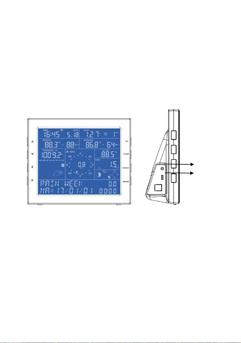
Display console ..................................................................................................4
Features.............................................................................................................4
Set up Guide...............................................................................................................5
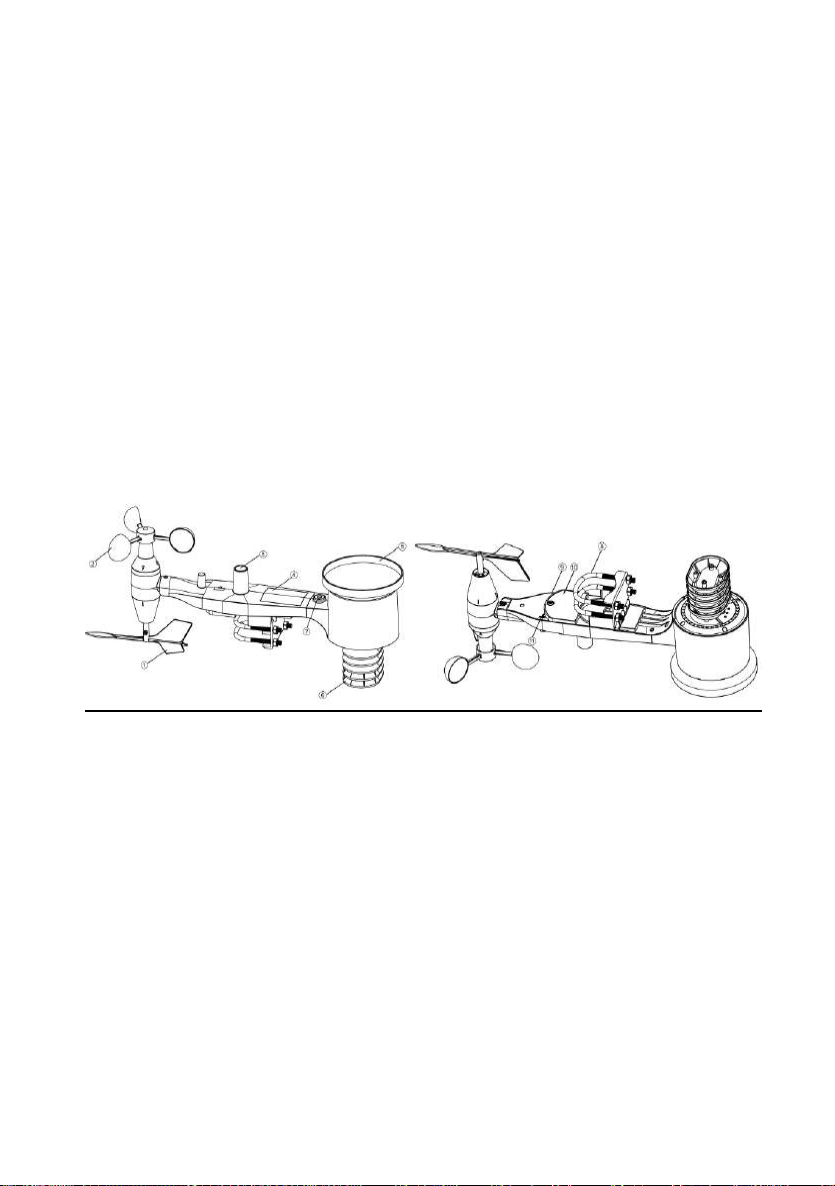
1. Outdoor Sensor Set Up..................................................................................6
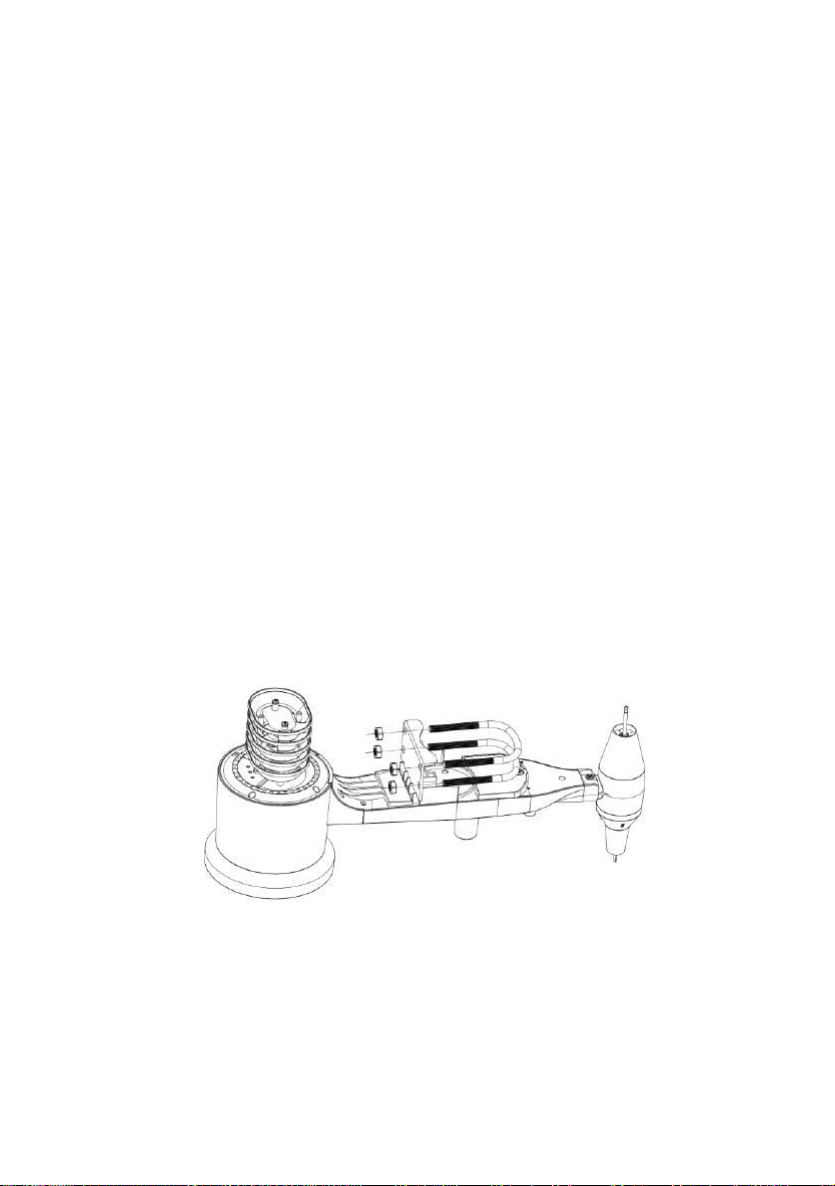
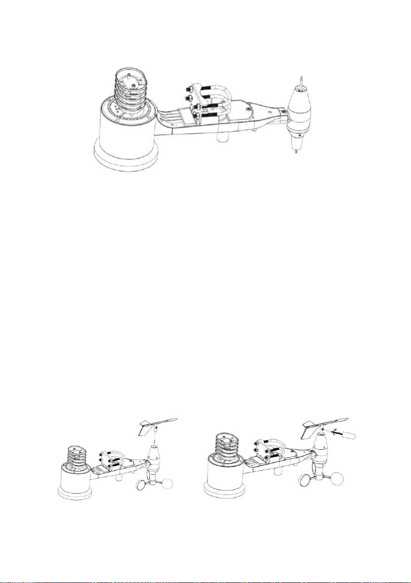
1.1. Install wind vane..................................................................................7
1.2. Install wind speed................................................................................9
1.3. Install Batteries....................................................................................9
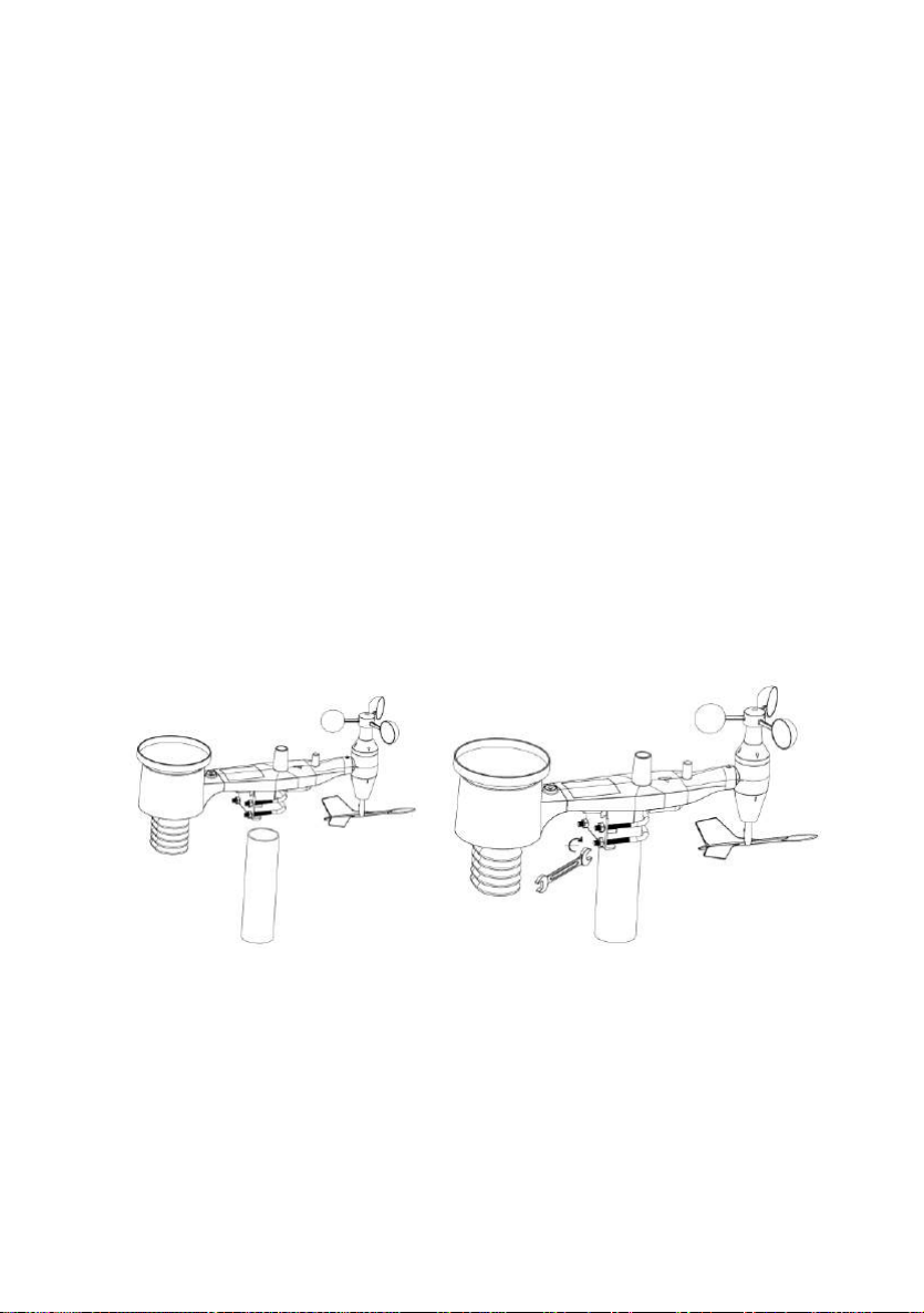
1.4. Mount outdoor sensor .......................................................................10
1.5 Reset Button and Transmitter LED.....................................................10
2. Best Practices for Wireless Communication.................................................11
3. Display Unit Set up.......................................................................................13
3.1. Display Console Layout.....................................................................13
3.2. Initial Display Console Set Up...........................................................14
Console Operation....................................................................................................16
Program mode..................................................................................................16
1. Quick Display Mode......................................................................................16
2. Setting Mode ................................................................................................23
3. ALARM MODE..............................................................................................30
4. Max/Min Mode..............................................................................................32
5. History mode ................................................................................................32
6. Other Console Functions...............................................................................33
6.1 Weather Tendency indicators..................................................................33
6.2 Moon Phases..........................................................................................33
6.3 Beaufort Scales (Wind Speed)................................................................34
6.4 Recording storage capacity used............................................................34
Specification..............................................................................................................35
Live Internet Publishing.............................................................................................36
1. WiFi Connection to the Weather Station ConsoleError! Bookmark not defined.
1.1 Download mobile appliacation .................. Error! Bookmark not defined.
1.2 Connect the console to Wi-Fi .................. Error! Bookmark not defined.
1.2.1 Android user .................................... Error! Bookmark not defined.
1.2.2 iOs user............................................. Error! Bookmark not defined.
2. Mobile application –Device list....................... Error! Bookmark not defined.
3. Mobile application –Check WU weather data and graphError! Bookmark not defined.
4. Mobile application –Remove or Add WU ID... Error! Bookmark not defined.
5. Mobile application –Set Units ........................ Error! Bookmark not defined.

2
Registering WeatherUnderground.com through the PC or Mac................................65
PC Software Operation.............................................................................................65
Maintenance.............................................................................................................72
Troubleshooting Guide..............................................................................................73
About this manual
Thank you on selecting this Professional WI-FI Weather Station! This
device provides accurate weather readings and is Wi-Fi capable to
stream live data from your weather station to the internet so that users
can run remote monitoring of weather condition.
This manual will guide you step-by-step through setting up your device.
Use this manual to become familiar with your professional weather
station and save it for future reference.
Glossary of Common Terms
NIST
This is a internet based time service, display time is updated every day
to keep time accurate on display.
LCD
“LCD” is an acronym for ”Liquid Crystal Display”. This is a common
type of display screen used in televisions, computers, watches, and
digital clocks.
BAROMETER & BAROMETRIC PRESSURE
A barometer is a device that measures the pressure of the air pushing
on it—this measurement is called the barometric pressure. We don’t
actually feel the barometric pressure because the air pressure is
pushing equally in every direction.

3
RELATIVE AIR PRESSURE
Relative air pressure is the same as the barometric pressure. The
calculation of relative air pressure is a combination of the absolute air
pressure and the altitude.
ABSOLUTE AIR PRESSURE
Absolute air pressure is the actual air pressure on the barometer
without regard to altitude.
INCHES OF MERCURY (inHg)
Inches of Mercury is the common unit of measurement for air pressure
in the United States.
HECTOPASCALS (hPa)
Hectopascals are the common units of measurement for air pressure in
the International System (SI) of measurement. The hectopascal holds
the same value
Package Content:
Below please find the package content:
QTY
Item
1
Display Console
1
DC Adapter
1
Outdoor Sensor (Thermo-hygrometer / Rain Gauge / Wind Speed
Sensor/ Wind Direction)
2
U-bolt with mounting clamps
1
User manual
Note:
A DC adaptor is included. For switching type adapter, it generates
interference and console should be placed at least 0.5m away from
display to get best RF reception.

4
An added feature of the Weather Station is that all the weather data and
programs can be viewed and set on a PC Software via Wi-Fi
connection.
OVERVIEW
Display console
Note: The backlight switch only works when the device is connected to
a DC adapter.
Features
⚫Time and date, Moon phase.
⚫Indoor temperature and humidity
⚫Outdoor temperature and humidity
⚫Wind chill, gust, wind direction.
⚫Rainfall
⚫Display rain level and rainfall data in 24 hours, one week, one
month, one year, total rain and rainfall event.
DC connector
Backlight
OFF/LOW/HIGH
Adjustable

5
⚫Wind speed in mph, km/h, m/s, knots or Beaufort
⚫Wind direction with 360 degrees
⚫Wind chill, dew point and heat index temperature display.
⚫Barometric, weather forecast.
⚫MAX, MIN value with time stamp.
⚫High/ low alarm.
⚫With message panel showing indication of alarms/Min/Max data,
with time stamps
⚫Light and UV index
⚫Save the data when batteries are changed
⚫PC software (require Wi-Fi connection;download the PC softare
from website )
⚫Upload the data to 5 weather server:
(Ecowitt.net, wunderground.com, Weathercloud , WOW and
customized website(Need to have the same protocol with
wunderground.com or ecowitt.net)
Set up Guide
Note:
Before placing and installing all components of the weather station at
their final destination, please set up the display console(receiver) and
outdoor sensor(transmitter) with all parts being nearby for testing the
correct function.
Power up sequence must be performed in the order shown in this

6
section (insert batteries in the Display Console firstly, Outdoor Sensor
secondly).
Attention:
⚫Do not mix old and new batteries
⚫Do not use Rechargeable batteries.
⚫Use Lithium batteries for sensor array when outdoor temperature is
lower than 0 degrees Celsius
⚫Ensure batteries are installed correctly with their polarity +/-
1. Outdoor Sensor Set Up
1. Wind Vane
2. Wind Speed Sensor
3. UV sensor/ Light sensor
4. Solar panel
5. Rain collector
6. Thermo-hygro sensor
7. Bubble level
8. U-Bolt
9. LED Indicator: light on for 4s if the unit power up. Then the LED
will flash once every 16 seconds (the sensor transmission update
period).

7
10. Battery door
11. Reset button
1.1. Install U-bolts and metal plate
Installation of the U-bolts, which are in turn used to mount the sensor
package on a pole, requires installation of an included metal plate to
receive the U-bolt ends. The metal plate, visible in Figure on the
right side, has four holes through which the ends of the two U-Bolts
will fit. The plate itself is inserted in a groove on the bottom of the
unit (opposite side of solar panel). Note that one side of the plate has
a straight edge (which goes into the groove), the other side is bent at
a 90-degree angle and has a curved profile (which will end up
“hugging” the mounting pole). Once the metal plate is inserted,
remove nuts from the U-Bolts and insert both U-bolts through the
respective holes of the metal plate as shown in Figure
Figure 1: U-Bolt installation
Loosely screw on the nuts on the ends of the U-bolts. You will tighten
these later during final mounting. Final assembly is shown in Figure
2.

8
Figure 2: U-Bolts and nuts installed
The plate and U-Bolts are not yet needed at this stage but doing this
now may help avoid damaging wind vane and wind speed cups later
on. Handling of the sensor package with wind vane and speed cups
installed to install these bolts is more difficult and more likely to lead
to damage.
1.2.Install wind vane
Push the wind vane into the shaft. as shown in figure 3.
Tighten the set screw with as shown in figure 4. Wind vane moves
not as free as wind speed sensor. This damp effect is helpful in
keeping wind direction measurement steady.
Figure 3 Figure 4
There are four alphabet letter of "N", "E", "S" and "W" around the

9
wind direction, representing for the direction of North, East, South
and West. Wind direction sensor has to be adjusted so that the
directions on the sensor are matching with your real location.
Permanent wind direction error will be introduced when the wind
direction sensor is not positioned correctly during installation.
1.3. Install wind speed
Push the wind cup into the shaft. as shown in figure 5.
Tighten the set screw with as shown in figure 6. Make sure the wind
speed spin freely.
Figure 5 Figure 6
1.4. Install Batteries
Insert 2XAA batteries in the battery compartment. The LED indicator
on the back of the transmitter will turn on for four seconds and
normally flash once every 16 seconds (the sensor transmission
update period).

10
Figure 7 Figure 8
Note: If no LED light up or is lighted permanently, make sure the
battery is inserted the correct way or a proper reset is happened. Do
not install the batteries backwards. You can permanently damage
the outdoor sensor
Note: We recommend lithium batteries for cold weather climates, but
alkaline batteries are sufficient for most climates. Rechargeable
batteries should never be used at all because they have lower voltages.
1.5. Mount outdoor sensor
Reference 9&10. The mounting assembly includes two U-Bolts and a
bracket that tightens around a 1 to 2” diameter pole (included) using the
four U-Bolt nuts.
Use the bubble level beside the rain sensor as a guide to verify that
sensors are level.
1.6 Reset Button and Transmitter LED
In the event the sensor array is not transmitting, reset the sensor
array.
Figure 9
Figure 10

11
With an open ended paperclip, press and hold the RESET BUTTON
for proper reset: LED turns on while RESET button pressed, and
resume normal after Reset button is released: LED will be lit
momently every 16s.
Figure 11
2. Best Practices for Wireless Communication
Note: To insure proper communication, mount the remote sensor(s)
upright on a vertical surface, such as a wall. Do not lay the sensor flat.
Wireless communication is susceptible to interference, distance, walls
and metal barriers. We recommend the following best practices for
trouble free wireless communication.
1. Electro-Magnetic Interference (EMI). Keep the console
several feet away from computer monitors and TVs.
2. Radio Frequency Interference (RFI). If you have other 433
MHz devices and communication is intermittent, try turning off
these other devices for troubleshooting purposes. You may
need to relocate the transmitters or receivers to avoid

12
intermittent communication.
3. Line of Sight Rating. This device is rated at 300 feet line of
sight (no interference, barriers or walls) but typically you will get
100 feet maximum under most real-world installations, which
include passing through barriers or walls.
4. Metal Barriers. Radio frequency will not pass through metal
barriers such as aluminum siding. If you have metal siding, align
the remote and console through a window to get a clear line of
sight.
The following is a table of reception loss vs. the transmission
medium. Each “wall” or obstruction decreases the transmission
range by the factor shown below.
Medium
RF Signal Strength Reduction
Glass (untreated)
5-15%
Plastics
10-15%
Wood
10-40%
Brick
10-40%
Concrete
40-80%
Metal
90-100%

13
3. Display Unit Set up
3.1. Display Console Layout
1.Time
2.Indoor Temperature
3.Indoor Humidity
4.Barometric Pressure
5. Barometric Pressure graph
6.Weather Forecast icon
7. Dynamic information display area
8.RF signal
9. Alarm icon
10. Memory status
11.Wind direction
12.Rain fall
13.Wind speed/Gust speed
14.wind chill/Dew point/Heat index
15.Outdoor Humidity
16.Outdoor Temperature
17.UV index
18.Light
19.Date
20.Wifi Signal icon

14
3.2. Initial Display Console Set Up
3.2.1 The unit will turn on all segments of the LCD for 5 seconds
after power reset and display unit information(Frequency,
FSK/ASK, EU/USA, Version) , then the unit will start to
register the outdoor channel for 3 minutes.
3.2.2 Full display
3.2.3 Key function

15
SET: Enter the setting mode
ALARM: Display high or low alarm function / turn on/off the alarm
HISTORY: Display history records / return to normal mode
MAX/MIN: Display the MAX, MIN value
: Move to previous information( normal mode) or +
( programming mode)
: Move to next information( normal mode) or–
( programming mode)
:: Move to previous segment/move to main menu during
setting.
:: Move to next segment/ move to sub menu during setting.

16
Console Operation
Program mode
The screen is divided into 10 segments for selection and there are
message display panel on the bottom.
There are six program modes: normal, setting mode, history mode,
alarm mode, max/min mode and calibrated mode.
All the modes can be exited at any time by pressing the HISTORY key,
or waiting for a 30 second timeout to take effect.
Normally, if the segment selected have multi parts, press SET key to
choose different part. Example: the current section is RAIN, you can
press SET key to alternate the display of RAIN RATE, RAIN EVENT,
DAY, WEEK, MONTH, YEAR and TOTAL.
1. Quick Display Mode
In the normal mode press” ”or” ”key to switch among different
segments. The respective chosen segment will be marked with the
arrow symbol” ”. The selected segment also determines the
message(s) shown in the message panel on the bottom. These
messages rotate every 5 seconds.
The 11 digits on left are used to display text, the right side displays

17
figures. If there are multiple messages, they will change every 5
seconds, or you can push the “ ” or “ ” keys to force a change to
another message at any time. When alarm conditions are active,
corresponding messages will display here.
1.1Time and date
This segment displays the current time and date. When connected to
Wi-Fi, the time will be synchronized with the internet time (UTC Time,
you need to set the time zone for local time), If the arrow symbol “” is
in this segment, following information will appear on message panel:
1) Year, and day of week
2) Time of alarm and status of alarm(on/off)
3) Moon phase. (see Section “Other Console Functions”for detail)
1.2Light and UVI
This segment displays the current solar radiation (light) and ultra-violet
index (UV-index). The light is the overall intensity of sunlight and its
theoretical maximum varies with location and time of year. The actual
value also depends on atmospheric conditions (clouds, vapor, etc.) and
varies throughout the day. The UV-index is a value that gives an
indication of the strength of harmful UV radiation and can be helpful to
know when protection from the sun is advised.
If the arrow symbol “” is in this segment, following information with
time stamp will appear on message panel:

18
1) Maximum light strength value of the day.
2) Maximum light strength value since last reset
3) Maximum UV index value of the day.
4) Maximum UV index value since the last reset.
1.3Indoor temperature / humidity
This segment displays the current indoor temperature and humidity, as
measured at the location of console. If the arrow symbol “” is in this
segment, following information with time stamp will appear on message
panel:
1) Maximum indoor temperature of the current day.
2) Minimum indoor temperature of the current day.
3) Maximum indoor temperature since last reset
4) Minimum indoor temperature since last reset
5) Maximum indoor humidity of the current day.
6) Minimum indoor humidity of the current day.
7) Maximum indoor humidity since last reset
8) Minimum indoor humidity since last reset
1.4Outdoor temperature/ humidity
This segment displays the current outdoor temperature and humidity, as
measured at the location of the outdoor sensor package. When the
arrow indicator is in this segment, the messages that appear on the
message panel are the same as for the indoor conditions, except they
reflect outdoor conditions.

19
1.5Barometric
This segment displays the current barometric pressure, a historical
graph of pressures, and a pictorial weather forecast.
When the arrow symbol “” is in this segment, press SET key to shift
display absolute (ABS) or relative (REL) pressure. The absolute
pressure is the pressure measured at your console’s location (altitude).
Relative pressure refers to the pressure measured by your console
(absolute), corrected to the value that would exist if your station was
located at sea level. The relative pressure is what is normally published
by official weather stations.
Below the pressure values there is a historical graph. This graph can be
configured to display 12 or 24 hours of history and will give you some
insight into how pressure has been changing. Falling pressures typically
indicate worsening weather (to come), and rising pressures indicate
good/better weather is to come.
Below the graph you will see a pictorial forecast for the next 12 hours.
If the arrow symbol “” is in this segment, following information with
time stamp will appear on message panel:
1) Maximum relatively barometric pressure of the current day
2) Minimum relatively barometric pressure of the current day
3) Maximum relatively barometric pressure since last reset

20
4) Minimum relatively barometric pressure since last reset
5) Maximum absolute barometric pressure of the current day
6) Minimum absolute barometric pressure of the current day
7) Maximum absolute barometric pressure since last reset
8) Minimum absolute barometric pressure since last reset
1.6Wind and gust speed
This segment displays wind related information. Inside the circular
“compass rose”you will find two arrows (if they overlap only one will
be visible). The “thicker”arrow indicates the most recently measured
wind direction 16 seconds or less ago). The “thinner”arrow
represents the average wind direction in the prior interval of 16 seconds.
This allows insight into the change of direction of the wind.
When the arrow symbol “” is in this segment, press SET key to shift
display wind speed, wind gust and wind direction in degrees (thus
allowing more precision than just the arrows).
If the arrow symbol “” is in this segment, following information with
time stamp will appear on message panel:
1) Maximum wind speed of the current day
2) Maximum wind speed since last reset.
3) Maximum wind gust speed of the current day
4) Maximum wind gust speed since last reset.
1.7Wind chill, dew point, heat index
Table of contents
Other Froggit Weather Station manuals

Froggit
Froggit WH1080SE User manual

Froggit
Froggit WH5300SE Installation manual

Froggit
Froggit DP2000 User manual

Froggit
Froggit WS50 User manual

Froggit
Froggit WH6000 User manual

Froggit
Froggit HP2000 User manual

Froggit
Froggit WH3000 User manual

Froggit
Froggit HP1000SE User manual

Froggit
Froggit WH5500 User manual

Froggit
Froggit WH3000SE Installation manual
Popular Weather Station manuals by other brands

La Crosse Technology
La Crosse Technology 616146V4 Faqs

La Crosse Technology
La Crosse Technology WS-9060U-IT instruction manual

La Crosse Technology
La Crosse Technology WS-1516-IT instruction manual

Solight
Solight TE90 operating instructions

Bresser
Bresser Meteo Champ HD instruction manual

ADE
ADE WS 2136-1 operating instructions