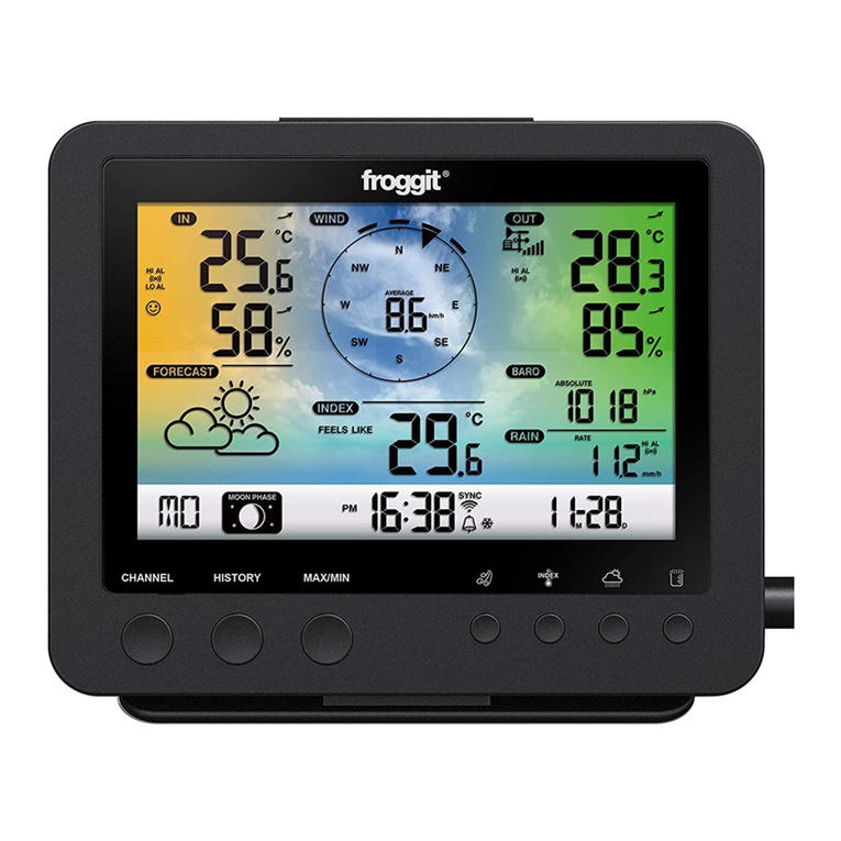
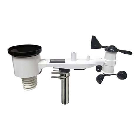
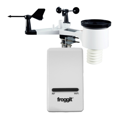
Froggit HP2000 User manual

1
HP2000
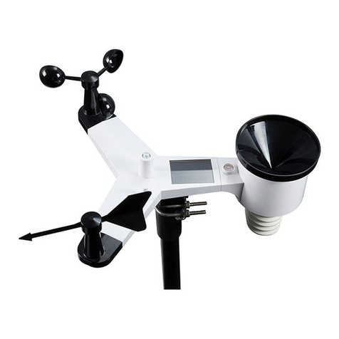
7-In-1 Ultra WiFi Internet Wireless
Weather Station
Manual EN
Support/updates/manuals/spare parts:
www.froggit.de

2
Table of Contents
1 TABLE OF CONTENTS
2 WARNINGS AND CAUTIONS
3 UNPACKING
4 OVERVIEW
4.1
D
ISPL Y CONSOLE
.................................................................................. 7
4.2
O
UTDOOR SENSOR
: ................................................................................ 8
4.3
O
PTION L SENSORS
.............................................................................. 9
5 SET UP GUIDE
5.1
P
RE
I
NST LL TION
C
HECKOUT
.............................................................. 12
5.2
O
UTDOOR
S
ENSOR
RR Y
................................................................... 12
5.2.1 Install batteries in sensor package .............................................. 12
5.2.2 Mount ultrasonic anemometer with piezoelectric assembly ........ 13
5.3
B
EST
P
R CTICES FOR
W
IRELESS
C
OMMUNIC TION
................................ 17
5.4
C
ONSOLE
D
ISPL Y
............................................................................... 18
5.4.1 Initial Display Console et Up ..................................................... 20
5.4.2 Key functions ............................................................................... 22
5.4.3 Main interface icons explain ........................................................ 23
5.5
M
ULTIPLE
C
H NNEL
S
ELECTION ND
S
CROLL
M
ODE
.............................. 25
5.5
H
ISTORY
M
ODE
.................................................................................... 25
5.5.1 View and Reset MAX/MIN ........................................................... 25
5.5.2 History Record Mode .................................................................. 27
5.5.3 View Graph ................................................................................... 29
5.5.4 View Channel Data ..................................................................... 30
5.6
S
ETTING
M
ODE
.................................................................................... 31
5.6.1 Date and Time setting ................................................................. 33
5.6.2 Time Format setting .................................................................... 34
5.6.3 Date Format setting ..................................................................... 35
5.6.4 Temperature unit setting ............................................................. 35
5.6.5 Barometric unit ............................................................................ 35
5.6.6 Wind speed unit .......................................................................... 35

3
5.6.7 Rainfall unit.................................................................................. 35
5.6.8 olar Rad. Unit ............................................................................ 35
5.6.9 Multi Channel ensor .................................................................. 35
5.6.10 Backlight setting ........................................................................ 37
5.6.11 Longitude: Latitude setting ........................................................ 38
5.6.12 Reset Weekly Rain .................................................................... 39
5.6.13 Rainfall season (default: January) ............................................ 39
5.6.14 toring Interval (1-240minutes electable) ............................... 39
5.6.15 Weather erver ......................................................................... 40
5.6.15 .1 Wunderground server setup ................................................. 41
5.6.15.3 Weathercloud server setup .................................................... 50
5.6.16 Wi-Fi scan ................................................................................. 62
5.6.17 Reset Daily Rain ....................................................................... 64
5.6.18 More .......................................................................................... 64
5.7
L RM
S
ETTING
M
ODE
......................................................................... 70
5.8
C
LIBR TION
M
ODE
.............................................................................. 71
5.9
F
CTORY RESET
................................................................................... 76
5.9.1 Re-register indoor transmitter ..................................................... 77
5.9.2 Re-register outdoor transmitter ................................................... 77
5.9.3 Automatic Clear Max/Min ............................................................ 77
5.9.4 Reset to Factory .......................................................................... 77
5.9.5 Clear History................................................................................ 77
5.9.6 Clear Max/Min ............................................................................. 78
5.9.7 Backup data ................................................................................ 78
5.9.8 About information ........................................................................ 79
5.9.9 Language .................................................................................... 79
6 OTHER CONSOLE FUNCTIONS
6.1
B
E UFORT
W
IND
F
ORCE
S
C LE
............................................................ 79
6.2
UVI
R
NGE
.......................................................................................... 80
T
HE
UV-
INDEX IS V LUE TH T GIVES N INDIC TION OF THE STRENGTH OF
H RMFUL
UV
R DI TION ND C N BE HELPFUL TO KNOW WHEN PROTECTION
FROM THE SUN IS DVISED
. ......................................................................... 80
6.3
W
E THER
F
OREC STING
...................................................................... 81
6.4
L
IGHTNING
LERT
.................................................................................. 82

4
6.5
W
E THER
F
OREC STING
D
ESCRIPTION ND
L
IMIT TIONS
....................... 82
6.6
M
OON
P
H SE
....................................................................................... 82
7 TROUBLESHOOTING GUIDE
8
SPECIFICATIONS

5
Warnings and Cautions
Warning: Any metal object may attract a lightning strike, including
your weather station mounting pole. Never install the weather station in a
storm.
Warning: If you are mounting the weather station to a house or
structure, consult a licensed electrician for proper grounding. A direct
lightning strike to a metal pole can damage or destroy your home.
Warning: Installing your weather station in a high location may result
in injury or death. Perform as much of the initial check out and operation on
the ground and inside a building or home. Only install the weather station on
a clear, dry, day.

6
Unpa king
Open your weather station bo and inspect that the contents are intact
(nothing broken) and complete (nothing missing). Inside you should find the
following:
QT
Item Des ription
1
Display Console
1
Outdoor Sensor
Array
with built
-
in: Thermo
-
hygrometer / Rain
Gauge / Wind Speed Sensor/ Wind Direction Sensor, Light and UV
sensor, Solar panel
1
AC adapter
1
W
hite O
-
ring
1
User manual (this manual)
Table: Pa kage ontent
If components are missing from the package, or broken, please contact
customer service to resolve the issue.
Note: Batteries for the outdoor sensor package are not in luded. You will
need 2 AA size batteries, alkaline or Lithium batteries (Lithium
recommended for colder climates).
Note: The console operates using an AC adapter. The included adapter is a
switching-type adapter and can generate a small amount of electrical
interference with the RF reception in the console, when placed too
close to the console. Please keep the console display at least 2 ft. or
0.5 m away from the power adapter to ensure best RF reception from
the outdoor sensor package.

7
Overview
Display onsole
Figure 1: Display onsole
1 Temperature, humidity and barometric 3-in-1 sensor
2. Micro SD card slot
3. USB Port
4. Power jack
Table 1: Display onsole identifi ation
Note: The USB port in the console of weather station is only for firmware
update, not for data communication (USB cable not included).
You can use a Micro SD card (ma 32G, Fat 32) for the firmware update.(SD
card not included).

8
4.2 Outdoor sensor:
Figure 2: Wireless Sensor Array
1. Solar Panel 7. Hapitac Rainfall sensor
2. Ultrasonic wind sensor 8. NORTH alignment indicator
3. Temperature & humidity sensor 9. Battery compartment
4. Fi ed Bolt (Mounting on a pole
with 1 inch diameter)
10. Heating power cable connector
5. USB port (Factory use only) 11. Reset button
6. Light & UV sensor, LED indicator 12.Calibration button (factory use
only )

9
Table 1: Sensor assembly detailed items
4.3 Optional sensors
The following optional sensors (purchased separately
) can be used with
HP2000 console display.
If you have purchase e tra sensors, just simple
power up, the display console
will receives the data automatically. If
sensor not reporting in to console
display console will re-search the data after one hour
or restart the console to
search the data. Please refer to the sensor manual (provided
sensor) for details.
This table shows the ma imum number of each type of
sensor
worked with console display
Sensor Image
DP50 Multi-channel temperature and
humidity sensor
DP100 Soil moisture sensor
DP200 PM2.5 air quality sensor
DP70 Water leak alarm
) can be used with
power up, the display console
sensor not reporting in to console
, the
or restart the console to
separately with
sensor
that can be
Maximum
Number
8
8
1
4

10
DP60 Thunder and lightning
DP250 Indoor PM2.5/PM10 CO2 air
quality sensor temperature/humidty
DP10 Leaf wetness sensor
* the data won’t be displayed on the main
screen, it will show its data on the
Channel Data page.
Sensor Image
DP35 stainless-steel probe thermometer
for soil and water
DP150 wire probe thermometer for water
DP35 and DP150 share the 8 channels
To pair the optional sensors with the HP2000
console, please follow the
below operations:
1. Place the optional sensor ne t to the console (keep 5-
10ft away from each
other).
2. Install batteries on the sensor and wait for 1-2 minutes.
3. Check whether the console will pick up the sensor data automatically and
display it on the screen.
4. If not, press the gear icon and go to Setup page -
find More and enter
its Setup page - find Sensors ID and enter its Setup page.
1
1
8
Maximum
Number
8
console, please follow the
10ft away from each
3. Check whether the console will pick up the sensor data automatically and
find More and enter

11
5. In the Sensors ID Setup page, find the sensor you want to pair - select the
ID number bo and register it.
6. Once successfully, you may return to the main interface to check the data.
Note:For above optional sensors
1. Console display just show the current data, the history data save in the
SD card.
2. WU website doesn’t support. Ecowitt.net can support these sensor data
upload.

12
Set up Guide
5.1 Pre Installation Che kout
To complete assembly you will need a Philips screwdriver (size PH0) and a
wrench (size M5; included in package).
Before installing the weather station on the place of operation, we recommend
placing the weather station at a temporary location with easy access for one
week. This will let you check all functions, ensure proper operation, and get
familiar with the weather station and its calibration procedures.
Attention:
Do not mi old and new batteries
Do not use rechargeable batteries
If outdoor temperature may go below 32F or 0C for prolonged periods,
Lithium based batteries are suggested over alkaline type batteries for the
outdoor sensor array
5.2 Outdoor Sensor Array
5.2.1 Install batteries in sensor pa kage
Insert 2XAA batteries in the battery compartment. The LED indicator(on
the top of the sensor) will turn on for 3 seconds and normally flash once
every 8.8 seconds (the sensor transmission update period).
If sensor has been put outside for some time, and solar panel has charged up
the internal accumulator fully or partially, if you install the 2 AA backup
batteries, the system might not start up properly. So you can always make a
system reset by press the “Reset” button. ?

13
Figure 3: Battery installation diagram
Note: If no LED light up or is lighted permanently, make sure the
battery is inserted the correct way or a proper reset is happened. Do not
install the batteries backwards. You can permanently damage the
outdoor sensor
We recommend lithium batteries for cold weather climates, but alkaline
batteries are sufficient for most climates. We do not recommend
rechargeable batteries. They have lower voltages, do not operate well at
wide temperature ranges, and do not last as long, resulting in poorer
reception.
5.2.2 Mount ultrasoni anemometer with piezoele tri assembly
Before you mount
Before installing your outdoor sensor in the permanent location, we
recommend operating the device for one week in a temporary location with
easy access. This will allow you to check out all of the functions, ensure
proper operation and familiarize you with the device performance.

14
1. Put the white O-ring on the out of the upper part of outdoor sensor array
for protection against moisture or water penetrated inside
2. Mounting on a pole as Figure 4. Make sure the mounting pole is
vertical, or very close to it. Use a level as needed.
Note: Supports poles 1” OD
Figure 4: Sensor mounting diagram

15
3.
T
here is an arrow icon with”N” words (Figure 5) representing the direction
of North. The sensor body has to be adjusted so that the “N” indication is
facing to real north direction in your location. A compass device is
recommended to help adjust direction. Permanent wind direction error will
be introduced when the outdoor sensor is not installed in right direction.
Figure 5 Fa ing North diagram
Note: In Southern hemisphere, it is not necessary to change the
orientation to SOUTH as its solar panel is a rounded type and it is
orientation free for its charging capability.
Make sure the mounting tube for the sensor package is installed
vertically (use a level at 90-degree offsets around the tube). Adjust the
mounting pipe as necessary. Ne t also make sure the mounting of the
anemometer body on the pipe is level. If it is not, wind direction and
speed readings may not operate correctly or accurately. Adjust the
mounting assembly as necessary.
4. During wintertime, to prevent ice formed on the reflection surface, the
optional e tension cord be connected to a 12v/1.0A outdoor type power
adapter as Figure 6 showed below.
After power by the adaptor, the built-in thermostat heating plate will
automatically turns on below 5°C (40°F) and atutomattically turns off
above 10°C (50°F), the heat plate will melts snow and ice and keeps its
anemometer working as usual.

16
Note: The outdoor rated adapter and e tended power cable can be
purchased separately:
Figure 6: Sensor pa kage mounting diagram
5.2.3 Reset Button and Transmitter LED
In the event the sensor package is not transmitting, reset the sensor.
Using a bent-open paperclip, press and hold the RESET BUTTON to affect a
reset: the LED turns on while the RESET button is depressed, and you can
now let go. The LED should then resume as normal, flashing appro imately
once every 8.8 seconds.
5.2.4. Calibration
The ultrasonic sensor has been calibration before leaving the factory. We do
not recommend that customers do calibration by themselves.
Customers use this feature only when the wind speed does not return to zero
when there is no wind
ccessory Part only, not included!

17
After the product works normally, use a cloth or sponge with good water
absorption (prevent the echo of the ultrasonic waves) to completely wrap the
air inlet.
With an open ended paperclip, press and hold the CAL button for three
seconds, the top LED light will be on. After releasing the CAL button, place
the product on the table. After five seconds, the top LED light will flash. At
this time it is in the calibration mode. Wait for the LED to flash, the
calibration is over, and the product automatically enters the normal working
mode.
5.3 Best Pra ti es for Wireless Communi ation
Wireless (RF) communication is susceptible to interference, distance, walls
and metal barriers. We recommend the following best practices for trouble
free wireless communication between both sensor packages and the console:
Ele tro-Magneti Interferen e (EMI). Keep the console several feet away
from computer monitors and TVs.
Radio Frequen y Interferen e (RFI). If you have other devices operating
on the same frequency band as your indoor and/or outdoor sensors and
e perience intermittent communication between sensor package and console,
try turning off these other devices for troubleshooting purposes. You may
need to relocate the transmitters or receivers to avoid the interference and
establish reliable communication. The frequencies used by the sensors are one
of (depending on your location): 433, 868, or 915 MHz (915 MHz for United
States).
Line of Sight Rating. This device is rated at 150 meter line of sight (under
ideal circumstances; no interference, barriers or walls), but in most real-world
scenarios, including a wall or two, you will be able to go about 50 meter.
Metal Barriers. Radio frequency will not pass through metal barriers such as
aluminum siding or metal wall framing. If you have such metal barriers and
e perience communication problems, you must change the placement of
sensor package and or console.

18
The following table shows different transmission media and e pected signal
strength reductions. Each “wall” or obstruction decreases the transmission
range by the factor shown below.
Medium RF Signal Strength Redu tion
Glass (untreated) 5-15%
Plastics 10-15%
Wood 10-40%
Brick 10-40%
Concrete 40-80%
Metal 90-100%
Table: RF Signal Strength redu tion
5.4 Console Display
See Figure 6 to help you identify elements of the console’s display screen.

19
Figure 7: Display Console S reen Layout
No Des ription No Des ription
1 Outdoor temperature 14 Last lightning strikes detected
time / distance; daily counts
(optional sensor)
2 Outdoor Feels Like/Dew
point/Humidity/10Min. Average
Wind Direction/Ma Daily Gust
15 Indoor humidity
3 PM2.5 concentration(optional
sensor)
16 RF signal bar for multi-channel
temperature and humidity
sensor(optional sensor)

20
Table: Display onsole detailed items
5.4.1 Initial Display Console Set Up
Immediately after power up (inserting power adapter), the unit will turn on the
display, and the unit will start to look for reception of the indoor and outdoor
sensor data. This may take up to 3 minutes.
4 RF signal bar for PM2.5
sensor(optional sensor)
17 Multi-channel temperature and
humidity sensor cycle display
mode icon(optional sensor)
5 Sunrise / Sunset Time 18 Multi-channel temperature and
humidity sensor channel
number (optional sensor)
6 Wi-Fi signal bar 19 Rain fall
Daily/Event/Hourly/Weekly/
Monthly/Yearly
7 Low battery power indicator for
each sensor
20 RF signal bar for Rain fall
sensor(optional sensor)
8 RF signal bar for outdoor sensor
array
21 Weather forecast
9 Wind direction/Wind speed/Gust 22 ABS/REL Barometer
10 Water Leak Alarm (optional
Sensor)
23 Moon Phase
11 Indoor temperature 24 UV
12 Date and time 25 Solar Radiation
13 Soil moisture(optional sensor)
Table of contents
Other Froggit Weather Station manuals

Froggit
Froggit WH2800 User manual

Froggit
Froggit WH5300SE User manual

Froggit
Froggit IP Observer WH2600 SE User manual

Froggit
Froggit WH4000 User manual

Froggit
Froggit WH5500 User manual

Froggit
Froggit WH6000 User manual

Froggit
Froggit WH5300SE Installation manual

Froggit
Froggit HP1000SE User manual

Froggit
Froggit WH3000 User manual

Froggit
Froggit WH3000SE User manual