6
INSTALLATION INSTRUCTIONS:
1. The installation shall conform with local codes, or, in the absence of local codes, with the National Fuel
Gas Code, ANSI Z223.1/NFPA 54, or the National Gas and Propane Installation Code, CSA B149.1.
2. Inspect the heater before each use and have it annually inspected by a qualified agency.
3. The hose assembly shall be visually inspected prior to each use of the heater. If it is evident there is
excessive abrasion or wear, or the hose is cut, it must be replaced prior to the heater being put into
operation. The replacement hose assembly shall be specified by the manufacturer. The hose assembly
shall be protected from traffic, building materials and contact with hot surfaces both during use and
while in storage.
4. When firing the unit in an enclosed area, five square feet (0.47 square meters) must be provided to
allow free entry of the air required for operation.
5. Do not operate the unit in partly ventilated areas without a flue pipe connected to the unit.
6. Do not operate the unit in close proximity to combustible surfaces, materials, gasoline, and other
flammable vapours and liquids.
7. After installation, check the manifold assembly for gas leaks by applying a water and soap solution to
each connection.
8. The heater must be installed on level ground.
9. Minimum gas supply pressure is 7" . .W C (natural gas) or 10” W.C. (propane). Maximum gas supply
pressure is 14" W C. . (1/2 PSIG)
GAS LEAKAGE TESTING
After removal for service or replacing components on the gas manifold a gas leakage test must
be performed.
1. Close main gas firing valve on the gas manifold.
2. Connect your source gas to the gas manifold.
3. Once connections are tightened, open source gas, fire unit.
4. On each connection and fitting, apply soap solution and check for bubbles. This will indicate a
gas leak if bubbles continue to form.
5. Fix any leaks that are found by applying pipe dope to the leaking fitting or connection and re-
tighten. Check for leaks once repairs, if any, are made.
6. Open main gas firing valve and start the unit.
7. Once the unit is operating and burner is running, redo the soap test to insure gas fittings are tight.
8. Fix any leaks found.
HIGH LIMITS
- The heater is supplied with manual reset high limits located behind marked panels on the left
side of the heater - SEE PAGE 12.
- The high limit contacts are normally closed and open on the high limit temperature condition.
- If a high limit trips allow the heater to cool down and reset. Reset the manual high limit by
manually depressing the reset button located in the center of the high limit.
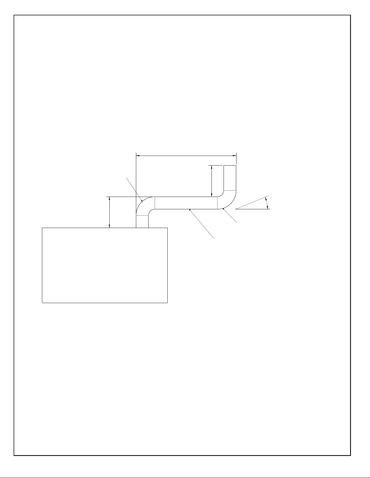
-Duct diameter is 16 inches
-Use belt cuff ducting. Slide the cuff overtop of the duct inlet/outlet and tighten with the belt.
-The top two connections are the heated supply air into the building.
-The bottom two duct connections are for cold air or return air into the heater.
-The heater is approved use with or without ducting.
-Maximum duct length is 100 feet per supply opening. If return air ducting is used the length of the
return air duct must be subtracted from the allowable supply ducting length (i.e. if the return air
duct length is 30 feet the maximum supply duct length is reduced to 70 feet).
-Ducts should be rated for 300°F minimum.
DUCTING: