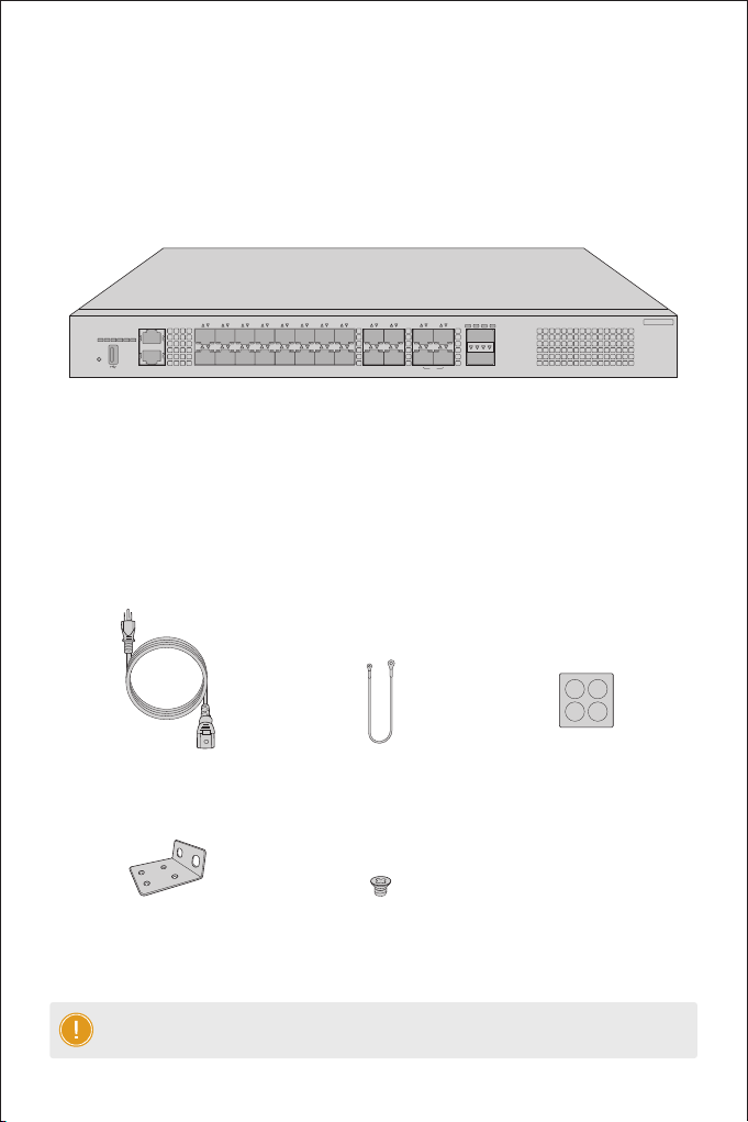
Before you begin the installation, make sure that you have the following:
Site Environment:
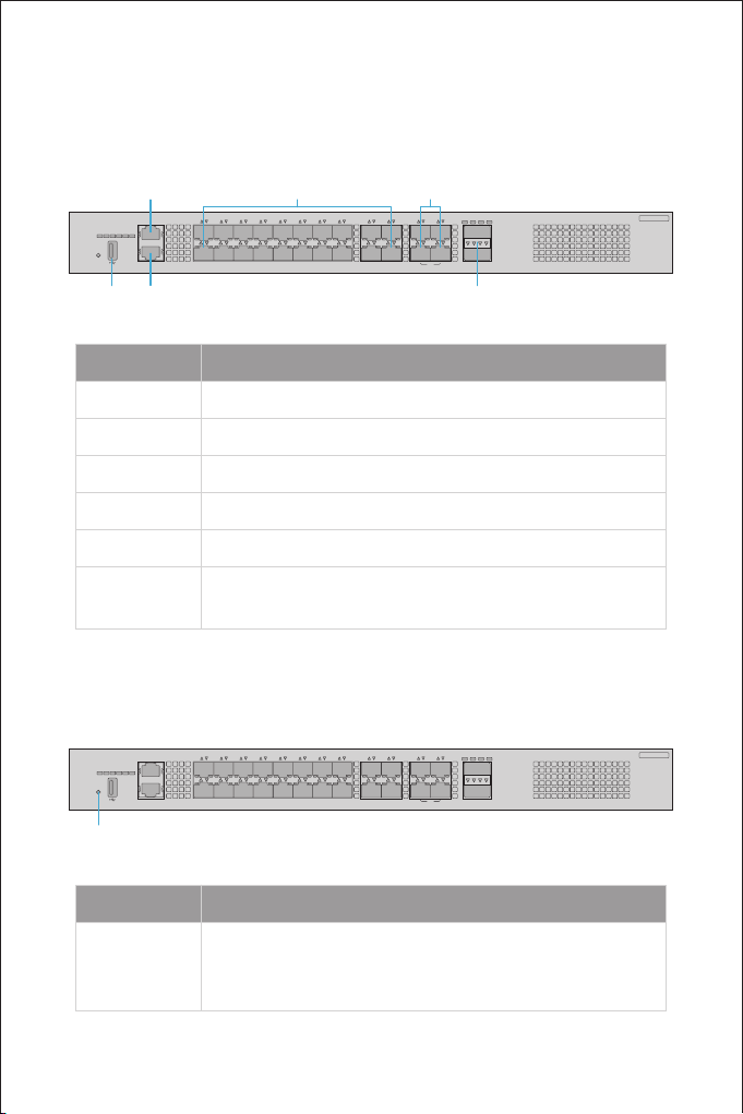
Description
The locator is controlled by CPLD by default.
The SFP+ port is NOT connected.
The SFP+ port is connected at 1/10G.
The SFP28 port is NOT connected.
The SFP28 port isconnected at 10/25G.
The QSFP+ port is NOT connected.
The QSFP+ port is connected at 10/40G.
The QSFP+ port is transmitting or receiving
data at 10/40G.
The SFP28 port is transmitting or receiving
data at 10/25G.
The SFP+ port is transmitting or receiving
data at 1/10G.
The locator is controlled by O&M personnel
remotely.
O
O
O
O
Solid Green
Blinking Green
Solid Green
Blinking Green
Solid Green
Blinking Green
Solid Blue
LEDs
ID
SFP+
SFP28
QSFP+
Status
Installation Requirements
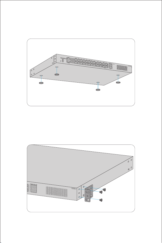
Phillips screwdriver.
Standard-sized, 19" wide rack with a minimum of 1U height available.
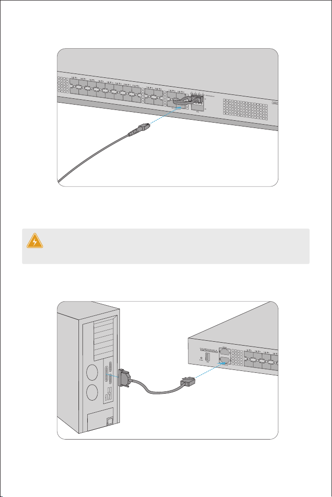
Category 5e or higher RJ-45 Ethernet cables, ber optical cables and console cable for connecting
network devices.
Do not operate it in an area that exceeds an ambient temperature of 50°C.
The installation site must be well ventilated. Ensure that there is adequate airow around the
switch.
The switch should be installed at least 1U (44.45mm) away from devices to its sides.
Be sure that the switch is level and stable to avoid any hazardous conditions.
Do not install the equipment in a dusty environment.
The installation site must be free from leaking or dripping water, heavy dew, and humidity.
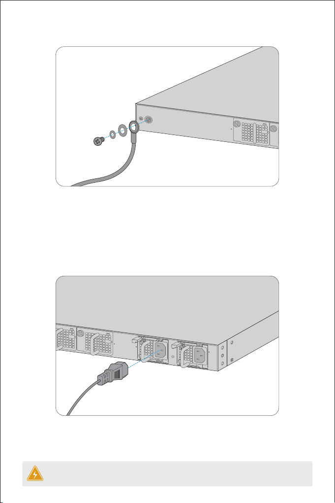
Ensure rack and working platforms are well earthed.