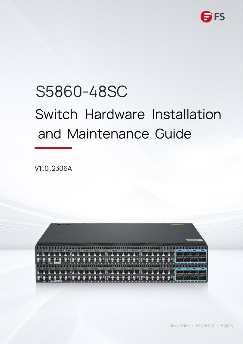
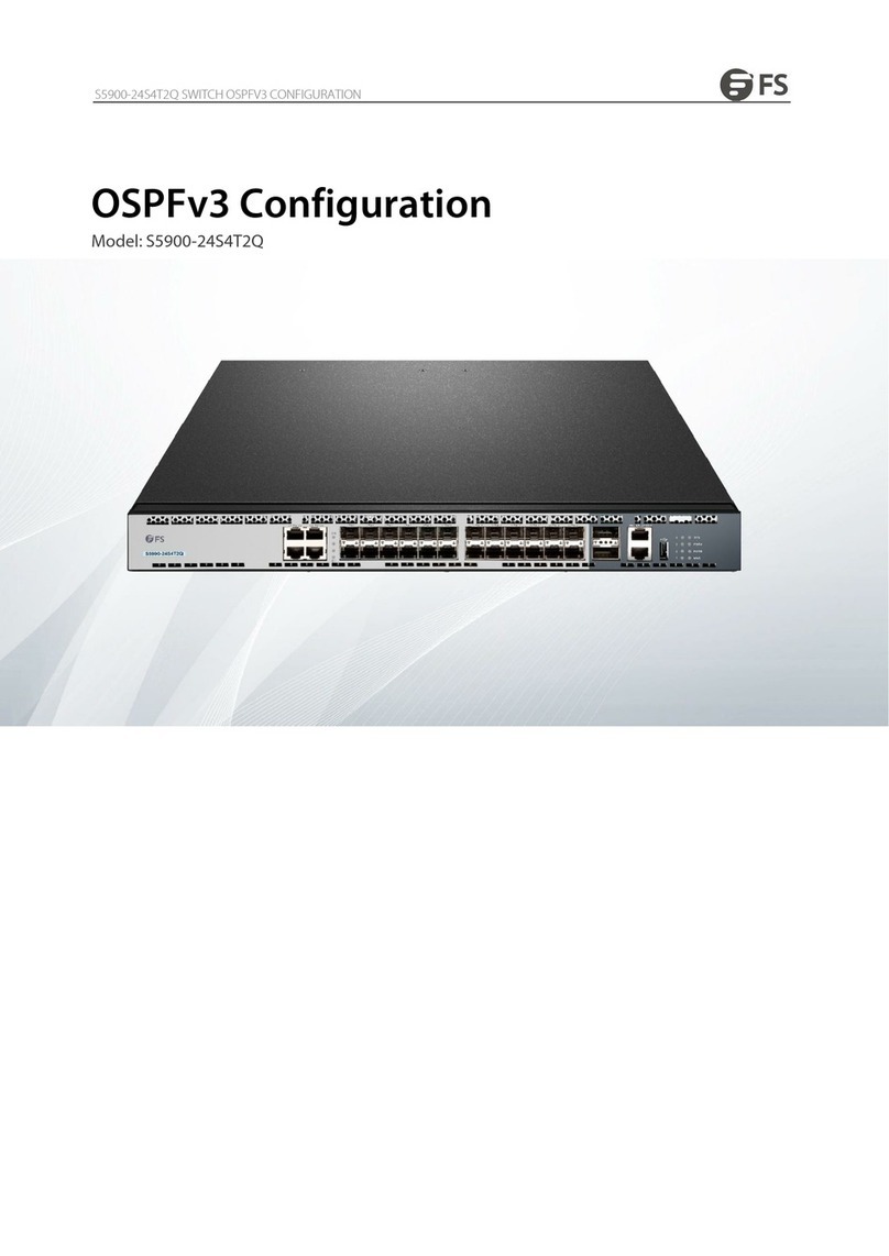
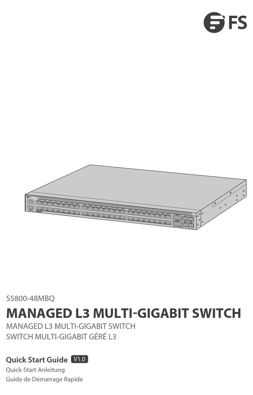
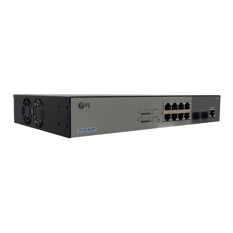
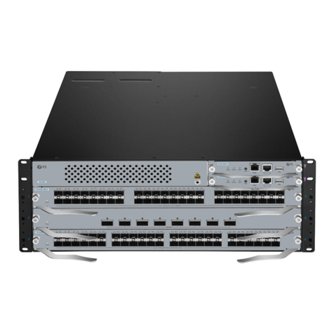
FS S5800-48F4S User manual

<>
。
\/
<>
。
0 ° 0
oo 0
。
0 0 0
。
S5800-48F4S Switch
lnstallati
。
n
Guide
§
FS

Warranty
&
Safety
Information
FS.COM
provides
a
limited
warranty
for
twelve
(12)
months
from
Purchaser's
receipt
of
the
Equip
『『
1ent
repre
回
nted
in
this
d
血
sheet
against
def
蚓
ive
design
or
wo
「阳
nanship.
FS.COM
provides
high
quality
produc
恼,
and
does
try
to
meet
customers'
requi
『
ements,
howeve
「,
in
few
cases,
you
are
not
satisfied
with
ou
「
goods,
don'
t
worry
about
th
创,
you
can
always
enjoy
a
30-day
any
reason
return
and
replacement
policy
in
FS.COM
if
you
are
not
satisfied
with
ou
『
products:
each
pa
『
ty
is
「
·esponsible
fo
『
the
freight
(『
eturn
o
『
shipping
cost
)「
espectively.
FS.COM
will
pay
the
freight
if
the
return
is
due
to
quality
problems.
If
』
howeve
『
FS.COM
reasonably
dete
「
mines
that
the
item
is
functional,
the
customer
shall
pay
any
freight.
What'
s
mo
『
e,
if
you
have
some
questions
about
usage
of
you
『
purchase,
you
can
w
「
ite
an
email
to
our
se
『
Tell
us
your
problems,
then
we
will
do
ou
『
best
to
help
you.
A
Ca
…
ltipl
叫「……叫
To
de
ener·
叫阿「
c
…
s
「
1
锦
d
to be
remov·
创,
including
RPS
cable
ifprovided.
A
叫:…倒
叫
arts
ins
…出
servic
叫
t
四
hnica
川
tied
personnel.
FαTechnical
Sup
严
xt:www.fs.αJITl/service.html

II
Contents
Chapter1 Ethernet Switch Introduction
.....................…..........
1
1.1
Overview
.............….........…….........…..........................…................................…......1
Chapter2 Product Characteristics
.............................…..........
2
2.1
Da
国
Center
Grade
Hardware
Design
..….........................……......................…...........2
2.2
Reliability
Design
.............................................…........…..........................….........…
.2
2.3
Metro
Ethernet
Network
Features
.................….........…................................…….......2
Chapter3 Description
of
Hardware
..….......................…..........
3
3.1
S5800-48F4S
Switch
Front
阳
nel
.............…............................................................3
3.2
S5800-48F4S
Switch
Rea
「
Panel
......................…......................…........................…3
3.2.1
Ethernet
向时........….........….........….........….........…...................….....................….........….........…........
4
3.2.2
Console
Port
....…..........................…….................................................................................……............
4
3.3
S5800-48F4S
Switch
LED
Introduction
.............…....................................................5
3.3.1
Sys
饱『
n
LED
Indicator
….........…...............….........”................”................”..........”..........”..........”........5
3.3.2
阳
N
LED
lndi
臼
tor
................….........….........….........….........…...............................….........….................
5
3.3.3
Powe
『
Supply
LED
Indicator
.......….........….........….........….........….........…...................….........…...........
5
3.3.4
日
hemet
Management
Inter
阳
.ce
LED
lndi
四”
r
........….......….........….........….........…...................…........
6
3.3.5
1
OG
Bas
。
x
SFP+
LED
Indicator
........….......….........….........….........…...................….......”….................
6
3.3.6
1
OG
SFP+
Indicator
(NM-4SFP+)
........….........….........….........…...................….........….........…..............
6
Chapter4 Introduction
to
Installation Accessories.................7
FαTechnical
Support: www.fs.com/service.html

Ill
Contents
Chapter5 Installation ...............…............................................8
5.1
p
「
eparation
fo
『
In
目
allation
..….......................................................…·…...................
8
5.1.1
Safi
向
Precaution
…··….......…··….......…··….......…··…··…··…….......………………………………
.8
5.1.2
Installation
Site
.................................................................……........................................…..................
8
5.1.3
Installation
Tools
.....................................................................…........…..........................................…..
11
5.2
Ins
幅
llation
..............................................................................................................
11
5.2.1
Introduction
of
Mounting
Brackets
..........…......................…............….........….......…...............…........
11
5.2.2
Install
the
switch
into
a
Rack
with
Front
Mounting
Brackets
..….........….........….........….......…·…..........
12
5.2.3
Ins
剧
l
the
Switch
on
a
Wo
『陆
ench
..........….........….........….........…......................................................
13
5.2.4
Ins
刷
lation
and
Removal
of
向
wer
Module
..........….........….........…....................................…...............
14
5.2.5
Installation
of
Fan
Module
..…...........................................................................................................…
.15
5.3
Grounding
Connection
..............................................................................................
16
5.3.1
Grounding
Connection
........….........…...................................…........................….........…................…..
16
5.4
Powe
『
Wire
Connection
.........….........................................….........…....................…
17
5.4.1
AC
阳
1wer
Wire
Connection
..........….........….........….........….........….........….......…·…..........…...............
17
5.4.2
DC
问
wer
Wire
Connection
..................….........….........….........….........................................................
18
Chapter6 Initial Power-on and Start-up
of
Switch................ 20
6.1
Building
Configuration
Pia
甘
0
『
m
and
Connecting
Cable
...........…..........….................
20
6.2
Setting
Te
『
minal
Paramete
『阳
ndows
Supe
『
Te
『
minal)
..……..............……................
20
6.3
Setting
Te
『
minal
Paramete
『(
SecureCRT
from
VanDyke
Software)
............................
23
6.4
Switch
Power-on
..................…….........…....................................………................…
25
F
口
rTechnical
Support:
www.fs.com/s
田
vi
口
e.html

IV
Contents
Chapter 7 Switch Software Loading........…............................26
Chapter 8 Upgrade
of
Operating System...............................28
Chapter 9 Maintenance and Troubleshooting........................29
9.1
Loading
阳
ilure
Processing
.......….......……......................….....................................
29
9.2
User
阳
ssword
Lost
.................…........................…......................….............…........
29
9.3
Power
System
Troubleshooting
...............................................................................
29
9.4
Configuration
System
Troubleshooting
.................................….........…................…
.
29
F
口
rTechnical
Support:
www.fs.com/s
田
vi
口
e.html
Chapter
1
Ethernet
Switch
Introduction
1.1
Overview
85800
-
48
问
S
routing
switch,
layer
3
multi-protocols
Gigabit
and
1O
Gigabit
Ethernet
switching
product
is
a
new
generation
of
intelligent
routing
switch
designed
to
meet
the
requirements
for
high
pe
时
ormance
and
high
「
eliability.
The
S5800-48F4S
switch
is
mainly
ta
「
geted
at
custome
币’
needs
fo
「
enterp
「
ise
O
「
car
「
ie
「
network
aggregation
O
「
access
layer.
It
has
48-port
1G
SFP
and
4-port
1
OG
SFP+
in
a
compact
1
RU
form
facto
「
and
low
latency
L2/L3
Ethernet
switch.
Hardware
suppo
时
for
1Pv4
&
I
问
6
dual
stack
and
rich
MPLS
features
and
enhanced
multicast
and
QoS
capabilities
can
p
「
ovide
customers
with
a
wealth
of
business
features
and
routing
functions
,
as
well
as
hardware-based
security
features.
The
S5800-48F4S
hardware
provides
high-availability
features,
including
pluggable
redundant
fans
and
using
high
quality
electronic
components.
It
provides
high
po
时
density
with
48G
fixed
po
时
and
adopts
flexible
modula
「
design
to
sup
po
叫
maximum
4x1
OG
uplink
.
====
三
7
飞-
---.--------.-
---.------.-----..-了一
.
.一
.
.
· .
.....
画面
illlllliiiiillllliiiil
一一
iiilll
一
iiilll
一二二
.
·
·....…….·.·.·.·....
…"”…·.......…·.”…·
量
Z
•=•=
• : :
:::
Figure
1-1
The
S5800
-
48F4S
Swit
ch
For
Techn
i
ca
l
Su
ppo
rt
:www.fs.com/se
rv
i
ce
.html

Chapter
2
Product
Characteristics
2.1
Data
Center
Grade
Hardware
Design
•
Pluggable
redundant
也
ns
and
powe
「
supplies
•
High
quality
electronic
components
•
Lowpowe
『
consumption
2.2
Reliability
Design
•
Suppa
「
tVRRP
•
Support
MLAG
and
VARP
•
Suppa
「
t
Sma
此
Link
and
Manito
「
Link
2.3
Me
甘
o
Ethernet
Network
Features
•
Suppa
『
t
QinQ
and
Vian
Translation
•
Suppa
「
t
MPLSNPLSNPWS/L3VPN
•
Suppa
『
t
G.8031/G.8032
•
Suppa
内
802.1ag
(CFM)
and
802.3ah
(EFM)
2
FσTechni
恼
I
Support: www.fs.com/service.html

3
Chapter
3
Description
of
Hardware
3.1
S5800-48F4S
Switch
Front
Panel
Figure 3-1
F
『
ont
Pa
n
el
Sketch
Map
of
S5800·4BF4S
Switch
(
100/1
OOOBase
-X
SFP
Ethernet
Po
巾
(
100/1
OOOBase-X
SFP
Ethernet
p
。由
Status
LED
(
SFP+
Network
Uplink
Card
(
SFP+
Network
Uplink
Ports
Status
LED
(
SFP+
Network
Uplink
Po
由
(
Airflow
Input
Holes
(
Management
Ethernet
lnte
巾
ce
3.2
S5800-48F4S
Switch
Rear
Panel
(
RJ45
Console
Po
时
⑦
USB
lnte
付出
e
(Extend
Flash
Memory)
(
System
Status
LED
(SYS)
@
Fan
LED
(FAN)
③
Powe
「
Supply
1
LED
(PWR1)
(
Pow
er
Supply
2
LED
(PWR2)
Figure 3-2
Rea
『
Pane
l
Sketch
Map
of
S5800
-
48F4S
Switch
①
G
「
ounding
Screw
(
Fan
Module
(
Fan
Module
Handle
(
AC
or
DC
Power
Supply
Module
(FRU)
(
Fan
of
Power
Supply
Module
(FRU)
(
Power
S
叩
ply
Module
Handle
(
AC
or
DC
FRU
Powe
「
Supply
Module
(PS1)
(
AC
or
DC
FRU
Powe
「
Supply
Module
(PS2)
For
Technica
l
Support
:
www.fs.com
/
serv
i
ce
.h
tml

4
A Cauuo
If
y
。
u
n
盹
d
t
。
in
硝
all
。「陌
mσ
》
e
the
内
etw
。『
k
m
。
dule
’
please
tum
off
阳到帽
r
d甘巴刷
itch,
and
then complete the
relatE
划。
p
臼
mion.
3.2.1
日
hemet
Port
白朋
0-48F4S
『
outing
switch
is
i11
惚
grated
with
out-of-band
Ethernet
po
「部
whose
inrerfa
臼
s
are
1
00
Base-TX
O
「
10
B
田
e-T.
It
is
recommended
to
use
由
e
net
line
included.
3.2.2
Console
阳时
Console
port
u
皿
s
an
8-pin
阳-
45
connector.
When
conn
田
ting
the
console
port
of
switch
to
a
computer,
we
n
四
d
an
阳-
45-to-DB-9
a
由
p
阳回
ble.
It
is
recommended
阳
use
ttle
自由
I
line
enclo
部
d
in
ttle
in
血
Jlation
package.
D
-t
y
pe
c
o n
nect
。
r
(9-pin,m
al
e)
X1
Ne
tw
or
k
po
rt
con
n
ecto
r
(8-p
in
,RJl-
45
)
口~._
X2
Figure3-3D
回
ω
民』
45
翩翩
e
cable
印刷
fie
pin
I
时
ormatlon
臼
n
be
found
In
the
table
below:
T
础
>le
3-1
阳
-45-to-DB-9
cable
sequence
阳
45
Slgnal
Direction
DB-9
町
'S
(Cl
阳而
Sen
呻
一号,
8
2
DSR
{Data
Set
Ready)
-+
6
3
阳
D
阴阳
M
Da
刨
-+
2
4
GND
·..
5
5
GND
·..
5
6
TXDσransmltDa
回)
‘-
3
7
DTR
{Da
恒
Terminal
R
阁制
等-
4
8
用
S(R
四
uestTo
Sen
呻
‘一
7
For
Tee
却叫但
l
Support:
www.fs.α:>mlservlce.html

5
3.3
S5800-48F4S
Switch
LED
Introduction
3.3.1
System
LED
Indicator
T
曲
le3-2
lndicato
『
Status
On
G
『
een
Blinking
Quickly
(2H
功
Blinking
Slowly
(0.5H
司
SYS
Blinking
Quickly
(2H
斗
Amber
Blinking
Slowly
(0.5H
斗
On
。何
3.3.2
FAN
LED
lndicato
『
Tab
陆
3-3
Indicator
由
at
us
G
「
een
On
FAN
Ambe
「
On
。仔
3.3.3
Powe
『
Supply
LED
lndicato
『
T
曲
le3-4
Indicator
Status
G
「·een
On
PWR1
Am
be
「
On
Desc
『
iption
Sy
血
m
is
abnorma
问
The
system
is
power
on
but
CPU
is
not
running.
The
system
is
normal
『
unning.
The
sys
也
m
is
in
u-boot
initiation.
The
system
is
in
system
initiatio
『
l.
The
system
occu
「
alarm
or
error.
No
powe
「
O
「句血
m
is
not
run
o
『
abnormality.
Description
The
Fans/fan
tray
are
ok.
Fans
a
『
e
bad.
No
powe
「
O
『也
n
tray
is
absent.
Description
Power
supply
ok.
Power
supply
is
abno
「
mality.
0肝
Power
supply
is
absent
o
『
single
power
supply
abnormality.
G
「
ee
『
1
On
Power
supply
ok.
PWR2
Ambe
「
On
Powe
『
supply
is
abnormality.
.
0肝
Power
supply
is
absent
or
single
power
supply
abnormality.
Fo
『
Techni
饱
I
Support:
www.r
s
.com/
回
rvica.html

3.3.4
日
hemet
Management
Interface
LED
Indicator
Table3-5
Indicator
Status
Desc
「
iption
On
10/100M
po
同
link.
Green(L
甜)
时
f
Port
not
link.
ETH
On
Po
吐
link.
Green(Right)
Blinking
10/1
OOM
packets
receiving
or
transmitting.
时
f
Port
not
link.
3.3.5
1
OG
Base-X
SFP+
LED
Indicator
Table3-6
lndi
臼
1to
「
Status
Description
On
1000M
po
同
link.
G
『
een
Blinking
1
DOOM
packets
receiving
o
「
transmitting.
时
f
Port
n
创
link.
1-48
On
100M
port
link.
Arn
be
『
Blinking
1
OOM
packets
receiving
or
transmitting.
时
f
Port
n
创
link.
3.3.6
1
OG
SFP+
lndica
回
r
(NM-4SFP+)
Table3-7
lndicato
『
Status
Description
On
10G
po
内
link.
1-4
Gree
『
1
Blinking
1
OG
packets
receiving
O
『
transmi
田
ng.
0
仔
Po
『
t
n
侃
link
6
F
口
r
Techni
c
al
Sup
po
陀
www.fs.
co
m/
s
er
唱
cs.html

Chapter
4
Introduction
to
Installation
Accessories
4.1
Introduction
to
Installation
Accessories
Figure 4-1
Co
n
sole
Cable
Figure 4-2
Power
Co
rd
(Qty
.2)
Figure
4-3
Rack
Mount
Bracke
t
(Qty.2)
Figure
4-4
G
「
oundi
n
g
Cable
Figure
4-5
Bracke
t
Screw
(Qty.
10)
Figure 4-6
Rubber
Pads
(Q
ty.4
)
7 For
Te
ch
ni
ca
l
Supp
口
时:
www
.
f
s
.
co
m
/
s
e
阿
i
ce
.h
t
ml

8
Chapter
5
Installation
5.1
Preparation
for
Installation
5.1.1
Safety
Precaution
The
following
preca
川
ions
should
be
followed
to
avoid
equipment
damage
and
personal
i
时
ury
caused
by
improper
use:
•
Power
source
should
be
removed
before
cleaning
switches.
Do
not
use
w
民『
ags
to
wipe
switches
and
clean
switches
with
liquid.
•
Do
not
place
switches
near
wa·
恒
ro
「
in
a
wet
environment,
and
p
「
event
wate
「
or
moisture
from
entering
switch
chassis.
•
Do
not
place
switches
on
an
uns
胁
le
臼
se
or
table,
since
the
dropping
would
cause
serious
harm
b
圳
tches.
•
Maintain
good
indoor
ventilation
and
clear
airh
。
les
of
switches.
•
Switches
shall
work
normally
under
∞『「
ect
voltage,
so
make
sure
the
ope
『副
ng
voltage
agrees
with
the
vo
阳
ge
mar
抽
d
on
switches.
•To
「
educe
the
『isk
of
elect
『
ic
shock,
do
not
remove
its
enclosure
when
a
switch
is
wo
「
king,
and
don
’t
do
回
at
will
even
if
it
is
not
powered.
•
Anti-static
gloves
must
be
worn
when
replacing
inte
「
face
board
to
prevent
归
tic
ele
由
icity
from
damaging
veneer.
5.1.2
In
剖
allation
Si
恒
To
ensu
陪
a
normal
wo
『
k
environment,
S5800-48F4S
switch
should
have
the
following
requirements
fo
「阴阳
lace:
•
Ensure
that
there
are
some
spaces
at
the
inlet
and
outlet
of
switch
fo
「
heat
dispe
「
sion
of
switch
chassis.
•
Ensure
that
rack
and
working
platform
have
good
ventilation
and
heat
dispersion
systems.
•
Ensure
that
rack
and
wo
「
king
platform
are
firm
enough
to
support
the
weight
of
a
switch
and
its
accesso
「
iesfo
『
ins·
旭
nation.
•
Ensu
陪
rack
and
wo
『
king
platform
are
well
ea
巾
ed.
To
ensure
switches
maintain
a
lo
咱也m
s
剧
le
work,
the
installation
阴阳
lace
should
al
回
meet
the
following
「
equirements:
•
Temperature/Humidity
Requirements
To
ensure
the
normal
work
and
se
「
vice
life
d
酬
tches,
certain
temperature
and
humidity
should
be
maintained
inside
switch
「
ooms.
Longtime
highe
『
humidity
inside
switch
rooms
may
easily
lead
阳
poo
『
insulation
o
『
even
elect
『
ic
leakage
of
dielect
『
ics,
and
sometimes
cause
material
changes
in
mechanical
features
and
corrosion
of
Fo
r
Technical
Support: www.fs.co
m/service.html

9
metal
pa
巾;
if
the
relative
humidity
is
lower,
insulation
pads
could
dry
sh
「
ink
to
make
fastening
screws
loose.
Meanwhile,
in
the
d
「
y
climate,
lower
『
·e1ative
humidity
could
easily
cause
static
electricity
which
will
impose
harms
to
the
circuit
of
switch;
highe
「
temperature
would
be
even
more
harmful:
longtime
high
tempe
『
ature
would
accelerate
aging
process
of
insulation
mate
「
ials
to
忻州『
educe
the
reliability
of
switches
and
severely
affect
their
service
life.
Table
5-1
Temperab.Jre/Humidity
R
饲
uirements
Item
S5800-48F4S
Temperature
0
~
45
℃
Humidity
10%
~
95%
•
Cleanliness
Require
『『
1ents
Dust
is
a
big
h
但
ard
to
the
回
1feope
『
ation
of
switches.
lndoo
「
dust
阳|||「
1gon
甘
1e
switch
body
臼
n
臼
use
electro
归
tic
adsorption
to
make
poo
「
contact
of
metal
con
nee
阳「
'S
0
「
me
剧
contacts.
Especially
when
the
indoo
「
relative
humidity
is
lower,
el
田
trostatic
adso
『
ption
is
B
臼
ily
formed,
which
will
not
only
affect
equipment
service
Ii
旬,
but
also
e
臼
ily
lead
to
communication
failure.
Table
5-2
Dust
Con
恒
M
Requirements
In
阳
Itch
Room
Substan
臼
Unit
Concentration
limit
DUST
Particle/m3
ζ3
X1
04
(No
visible
dust
on
the
恒
bletop
fo
『
three
days)
Note:
The
dust
pa
此
icle
size
is
>5
µm
Besides
dust,
there
are
『
igo
「
uus
limits
on
the
content
of
ha
『
mful
substances
that
can
accelerate
the
corrosion
and
aging
of
metals,
such
as
sal
恼,
acids,
and
sulfides
in
the
ai
「
in
the
equipment
room,
and
the
equipment
room
must
be
protected
against
ingression
of
harmful
gases
such
as
S02,
H2S,
NHa,
and
Cl2.
For
the
specific
requirement,
see
the
following
恒
ble.
For
Technical
Support:
www.fs.com/service.html

10
Table 5-3
Harmful
Gas
Th
『
eshold
in
the
Equipment
Room
Gas
Maximum
concentration
(mg/m
司
S02
0.2
H2S
0.006
NH3
0.05
Cl2
0.01
•
Electromagnetic
Susceptibility
Switches
may
be
a
仔
ected
by
the
interfe
『
ences
from
outside
the
system,
which
will
have
an
e
仔
ect
on
devi
臼
S
through
conduction
of
capacitan
四
coupl
吨,
inductive
coupl
吨,
electromagnetic
wave
radiation,
common
impedance
Oncluding
ground
system)
coupling
and
wires
曲。
1werwi
用,
signal
wire
and
output
signal
wire,
etc.).
The
following
attention
should
be
paid
to:
一
AC
power
supply
system
is
TN
system,
and
AC
powe
『
socket
should
be
single
仙
ase
3-wire
outlet
with
protective
earth
(P
白白
that
fi
阳
circuit
on
devices
can
effectively
filte
『
inte
「
feren
四
from
electric
g
闹,
-
Places
where
switches
work
should
be
kept
away
from
strong-powe
「
radio
transmitti
咱也
1tion
,「
adar
transmit
ti
「
1g
station,
high-f
「
equency
high-current
devices.
一
Electromagnetic
shielding
should
be
adopted
when
necessary,
i.e.
inte
『
face
cables
use
shielded
cables.
一
In
饱
rface
cables
are
required
to
be
arranged
indoors
instead
of
outdoors
to
prevent
signal
po
叫
s
of
devices
from
being
damaged
by
ove
「
voltage
and
over
cu
『陪
nt
generated
from
lightning.
•
Laser
Use
Safety
-
S5800-48F4S
棚
itch
is
Class
1
laser
device.
一
Do
not
sta
『
e
at
the
optical
inte
厅
aces
directly
when
the
optional
optical
inte
厅
aces
of
S5800-48F4S
switch
is
in
operating
mode,
since
light
beam
emitting
from
fiber
has
high
energy
which
may
be
harmful
to
retina.
FαT
配
hni
臼
I
Support:
www.fsαxn/service.html

11
5.1.3
Installation
Tools
Prepare
the
following
tools
before
installation:
•
Flathead
screwdrivers
•
Phillips
screwdrivers
•
ESD-preventive
wrist
st「
ap
A
Gaut
…
5.2
Installation
S5800-48F4S
switch
can
be
installed
in
a
19"
standard
rack
in
the
following
3
ways:
•
Install
the
Switch
with
Front
Mounting
Brackets
and
a
Rack
Tray
•
Install
the
Switch
with
Front
and
Rear
Mounting
Brackets
•
Install
the
Switch
on
a
Workbench
5.2.1
Introduction
of
Mounting
Brackets
Mounting
Brackets(S5800-48F4S)
Figure
5”1
App
ea
ran
ce
SketchMap
of
Fro
ntMoun
ting
Br
ac
kets
F
or
Techn
i
ca
l
Support
:
www
.
fs.com/se
阿
i
ce
.
h
t
m
l

12
Description:
(
Screw
hole
for
fixing
F
「
ont
Mounting
Brackets
and
rack
(
Screw
hole
for
fixing
Front
Mounting
Brackets
and
switch
A
臼
uti
t Mounti
weight.
5.2.2
Install the Switch into a
Rack
with Front Mounting Brackets
Take
out
the
screws
(complete
package
with
mounting
brackets},
and
fasten
the
Front
Mounting
Brackets
with
Switch.
Please
take
the
following
installing
map
as
reference
figure
5-2
.
、.
.‘
’
·咱
Figure 5-2
Installat
ionS
ke
tch
Map
of
Front
Mount
ing
B
「
ackets
To
hold
and
inse
「
t
the
Switch
to
the
Rack
ho
「
izontally.
Use
the
screws
and
its
matching
floating
nut
to
fix
the
Front
Mounting
Brackets
upon
the
front
of
rack.
..
.,
Figure 5-3
In
sta
ll
a
tion
Sketch
Map
of
F
「
on
t
Mounting
B
『
邵阳
t
s
(
To
th
e
Ra
ck
)
F
or
T
echn
i
ca
l
Su
p
port
:
www.fs
.
c
o
m/se
『
v
i
ce
.
htm
l

13
5.2.31n
剖
all
the
Switch
on
a
Wo
血
bench
In
many
姐”
s,
use~
do
not
h
创曹
a
刽刨出
1
划
19
’ r
蚓飞
so
阳
)Ille
。“:
en
place
switch
峙。
n
a
cleaning
WOf
刷。
platform.
Such
op
阴
tion
is
relatively
simp
怡,
and
the
only
following
aspects
should
be
concem
国
during
叩
eration:
Ensure
the
州
1<ing
p
刷
m
is
灿
le
and
well
earth
盹
A
10cm
spa
院彻执
md
switch
is
I
钝
tor
heat
dissipa
阳
l.
Do
not
place
h
阳
Jl'j
0
剧院
ts
on
仰
i
剧由.
There
are
4
foot
pads
甘
1atcomewi
白
the
device.
阳
ste
them
onto
甘
lebO
阳
m
n
阅
rthe
倒四
ra of
由
ie
棚前
ch,
as
shown
below:
.
Figure
5-4
Ins
刷脑
tlonS
惚
tch
陶
pc
州市
e
拟就
pads
部创
0-48F4S
制
i
阶
sup
阴阳
Extend
Uplink
Netwo
欣$阳.
S5800-48F4S
创
ppor
恕”
plink
module:
NM-4SA>+.
Netw
创
k
mod
川
e
inS'
也
llalion
process
is
as
削
lows:
a
曹堕
a
w1
阳伽
eESD
圳蚊欲
m
段,栩
dcon
肯
m
仙
ean
a
塑堕.
四
sconn
似
all
酬
e
『棚
n
蚓
on
wi
防
1
制
itc
:h.
.
a
曹雪
.
N
阳阳州
mod
川
els
创制
y
Inserted
I
咖甘岭
network
创
ans
阳圳阳刚
umboftwo
hands
resp
部
tively
hold
left
and
right
ends
of
the
frame
at
Nat.work
Upllnk
Module,
and
push
to
甘
19
SW
忧
ch.
The
Uplink
Network
mod
川,
Is
aligned
州时
1
馆
1e
仿
W
忧阳刚制
Itch.
Forl<
锐如时
caJS~
以别:
WWW.
低
α)O'\/ser
悦。
e.htrr
曲

14
a
塑理
a
Withacro
创剧创酬
d
「
iver,
tighten
the
fa
归
ning sere
附
at
the
left
and
right
of
the
Uplink
Network
Module.
A C…eS5800…
itch
upl
…
rkmodu
…削
supp
叫
If
you
need to
inst
刽
lo
「
remove
the network
『
nodL
』
le
’
please
turn off powerofthe switch,
and then complete the
related
operation.
5.2.4
Installation
and
Removal
of
Powe
『
Module
Installation
Process
The
power
modules
fo「
S5800-48F4S
「
O
川
ing
swi
时
is
pluggable
.
Ins
饱||挝
ion
process
of
powe
「
module
is
as
follow
s:
:
a
噩堕
a
w
阳臼
D-p
「
even
a
理理
a
Maintai
门阳
re
ct
叶
down
direction
of
powe
「
module
(in
line
with
the
positive
direction
of
characters,
汗
turned
upside
down,
the
power
module
can
not
be
inserted
to
the
end
due
to
st
阳
ctural
limit
specially
designed
inside
chass
闷,
grip
the
handle
on
the
front
end
of
power
module
to
be
ins
恼
lled
with
one
hand
and
support
the
bottom
of
power
module
with
another
hand,
and
inse
时
the
powe
「
module
by
smoothly
sliding
along
the
power
slot
until
the
plug
of
power
module
comes
into
仙
H
con
旭
.ct
with
the
socket
inside
chassis.
a
理堕.
Tigh
怡
n
up
the
fa
阳
ing
screws
on
the
left
a
仙
ight
sides
of
power
module
with
a
cross
怕回
SC
陪
wd
「
iver.
The
following
are
the
complete
installation
s
阳
tch
map
of
the
AC
power
module.
The
installation
to
「
DC
powe
「
module
is
simila
「
with
AC.
Figure 5-5
Installation
Sketch
Map
of
AC
powe
『
module
For
T
ec
hn
ical
Su
ppo
rt
:
www.
fs
.
co
m/
se
rvice
.h
t
ml

Removal
Proce
臼
The
power
modules
fo 「
S5800-48F4S
routing
switch
is
pluggable.
Removal
proc
币
ss
of
powe
「『
nodt
」
les
is
as
follows:
:
a
塑哩.
Wea
『
1
『
lg
州-
s
恒
ticw
「
ist
st『
a
a
堕暨
a
Discon
ct
圳川盯
onne
归甩
d
删
i
也
h
臼.
a塑堕
a
u
『
ld
【1
the
旬
s
怡「
iing
screws
o
币
1
t
「
1e
le『
ta
『
1
a
冒堕.
Gripth
晦
ha
「
Idle
0
『
e
fro
「it
e
『
1
top
删
i
比
h
wi
甘
l
a
『
10t
『
16『
hand,
and
pull
out
the
power
module
by
smoothly
sliding
along
the
po
阴「
剖
ot
until
甘
1e
plug
of
powe
「
module
is
comple
恒
ly
separated
from
the
socket
inside
chas
由.
A
叫:刊
e
臼…
h
臼
n
民
in
喇|刨
with
two
阳阳剖…
When
。
neoft
『
ietw
。
p
。
wer
m
。
dul
臼刨
lu
陪,
user
佣
n
replace
the
U
副阳洲研
module
on
line
仰
ithout
interruption
for
Switch
powe
「
supply).
5.2.5
Ins
国
llation
of
Fan
Module
The
fan
module
of
S5800-48F4S
is
pluggable,
so
it
’s
e
臼
y
to
be
ins
恒
lied,
but
users
should
ensure
that
the
interval
between
removing
the
old
fan
module
and
inse
叫
ng
a
new
one
is
not
more
than
1
minute
du
『
ing
the
replacement
of
fan;
othe
『
wise
higher
temperature
in
switch
will
cause
damage
to
switches.
a塑堕.
Und
<1
the
旬
s
怡「
1ing
screws
o
币
1
t
「
1e
le『
ta
『
1
a
盟哩.
Hold
甘
1e
ha
『
idle
州
n
moα
【
ll
』
le,a
『
ld
g
州『
rtly
pull
out
the
fan
module.
a
冒霆a
lnse
new
far
backplane
of
the
swi
忧
h
and
i
时
egrated
wi
甘
1
it
closely.
.
a
理
la
Tighten
the
faste
川
SC
棚
son
both
sid
叫
owe
『
mod
川伽
a
screwdriver
to
fix
the
power
module.
15
Fo
r
Technical
Support: www.fs.com/service.html
Table of contents
Other FS Switch manuals

FS
FS S3410 Series User manual

FS
FS S5900-24S4T2Q User manual

FS
FS S5900-24S4T2Q Quick guide

FS
FS S1900-8TP User manual

FS
FS S3900 Series User manual

FS
FS S5500-48T8SP Operating instructions

FS
FS Fiberstore S8050-20Q4C User manual

FS
FS S3700-24T4F Instruction Manual

FS
FS S2805S Series User manual

FS
FS S3910 Series User manual