1510
A WORD ABOUT LATEX
Although Latex Paint was never originally intended to be sprayed, a
professional finish can be achieved by following a few simple rules.
(Please do not confuse Latex with the newer water-based coatings).
For work such as cabinetry or trim, our equipment can be used
successfully with Latex Paint. The Latex will have to be thinned with
WATER - approximately 10-30% depending on the brand of
paint. And to improve the finish even more, you can use an additive
that will slow down the drying process so that the paint levels out
nicely. One product available is Floetrol from the Flood Company in
Ohio. In the USA Call 1-800-321-3444 for your nearest supplier. (In
the U.K. 0845-0618899).
The recommended Air Cap size Setup is either the 1.5mm or 1.8mm
for household trim, louver doors etc. The Latex paint should be
‘finish-quality’ and not a cheaper grade.
When spraying Latex, please adjust the Fluid Knob 5221 to limit the
paint to a finer spray. This will increase the ratio of air to paint and
result in better atomization and a beautiful finish. (Factually speak-
ing, it doesn’t increase the ratio of air to paint but does the opposite
- it allows the air atomizing power to work on less paint thereby
improving the quality of atomization). Also, it is usually helpful to
remove the Air Control Valve so that more air passes through the
Spray Gun. Finally, adjust the pattern to a maximum size of 8” - 9”
(20cm) - smaller is ok. Apply a wet coating (wet like a lake).
Although it is possible to use our equipment for house painting
(walls), and many end users do, we feel that an airless gun or power
roller is better suited for that kind of job. However, if you decide to do
this kind of work, you will need the 2.0mm or 2.5mm Air Cap set.
Remember, when you buy a can of paint, lacquer, polyurethane,
varnish etc. over the counter, it will most likely be formulated for
brushing. That means, it will be too viscous (thick) and will require
thinning to spray successfully. This is true even when spraying is
mentioned on the label of the can. Check with the manufacturer of
the coating to obtain advice on thinning their product. Unfortunately,
sometimes you may encounter Technical Sales Personnel that have
very little experience or knowledge about HVLP Turbine spraying.
THE TRIGGER IS SLUGGISH
• The Needle Packing is too tight - see LEAKAGE FROM THE
NEEDLE PACKING NUT. Page 14
• Bent Needle
POOR SPRAY PATTERN
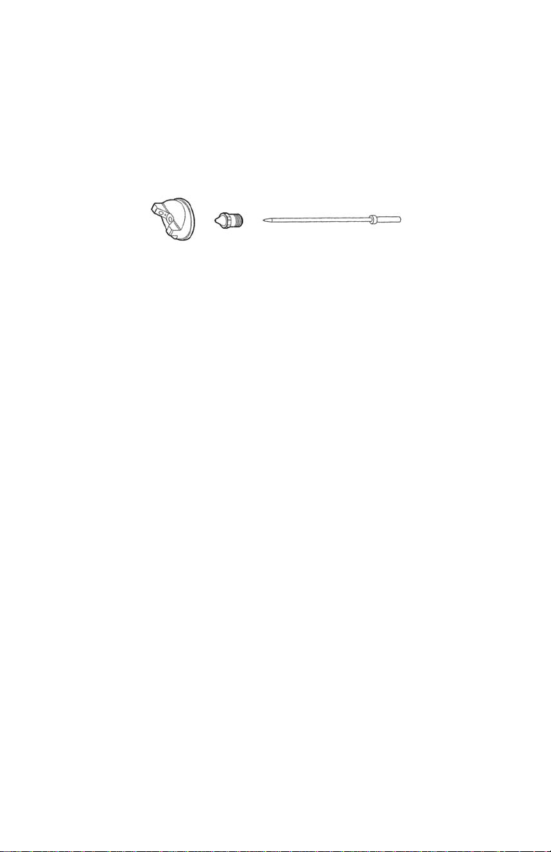
• Damaged Needle or Nozzle
• Nozzle is clogged
• Air holes in Air Cap clogged
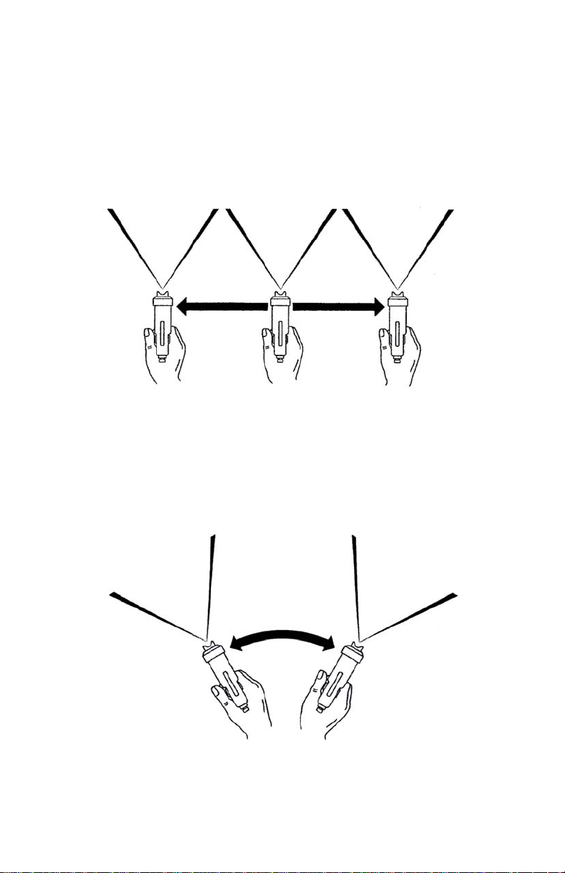
• Gun too far from surface (max. 8” - 20cm)
PAINT AT THE AIR NOZZLE HOLES
• The Fluid Nozzle is loose and material is leaking around it -
tighten with the supplied Wrench
• Paint is entering the gun via the Pressure Tube and being
blown through the barrel to the Air Cap
GUN SPRAYS IN A PULSATING MANNER
• The Needle Packing has worn a little or is loose. Tighten
• The Cup is almost empty
• The Cup Lid is not tight - air is escaping
• The clear Plastic Pressure Tube is leaking air. Replace
• The Pressure Tube and/or Nipple is clogged. Clear or replace
EXCESSIVE OVERSPRAY
• The spray pattern size is too large for the item being sprayed
• The Gun is being held too far away - should be 8” max. (20cm)
• Trigger on and off as you pass over the edges of the item
• The ‘paint’ is too thin - try thinning less
• Reduce the air by turning the Air Control Valve to the point
where overspray is minimized but the finish still looks good
• For ideal and comfortable spraying conditions, you should
install an extraction fan.* If you are spraying a flammable,
combustible product such as nitrocellulose lacquer, you must
install an explosion-proof fan (and explosion-proof lighting and
switches)
* Please check with the local jurisdiction on this matter.