manuals.online logo
Brands
  1. Home
  2. •
  3. Brands
  4. •
  5. Fujitsu
  6. •
  7. Air Conditioner Accessories
  8. •
  9. Fujitsu UTY-XWZXZ3 User manual

Fujitsu UTY-XWZXZ3 User manual

En-1
INSTALLATION MANUAL
PART NO. 9380228004
AIR CONDITIONER
OPTIONAL PARTS
External connect kit
For authorized service personnel only.
1. SAFETY PRECAUTIONS
WARNING
This mark indicates procedures which,
if improperly performed, might lead to
the death or serious injury of the user.
When installing each wire, please thoroughly read this•
manual.
Before installation be sure that all sources of power have•
been shut off. There is a danger of electric shock.
For External connect kit and locally purchased parts,•
apply voltage indicated on specications of parts.
Application of unspecied voltage may result failure or
malfunction of air conditioner.
CAUTION
This mark indicates procedures which,
if improperly performed, might possibly
result in personal harm to the user, or
damage to property.
Do not pull on the connectors with too much force.•
2. ABOUT THE UNIT
2.1. General
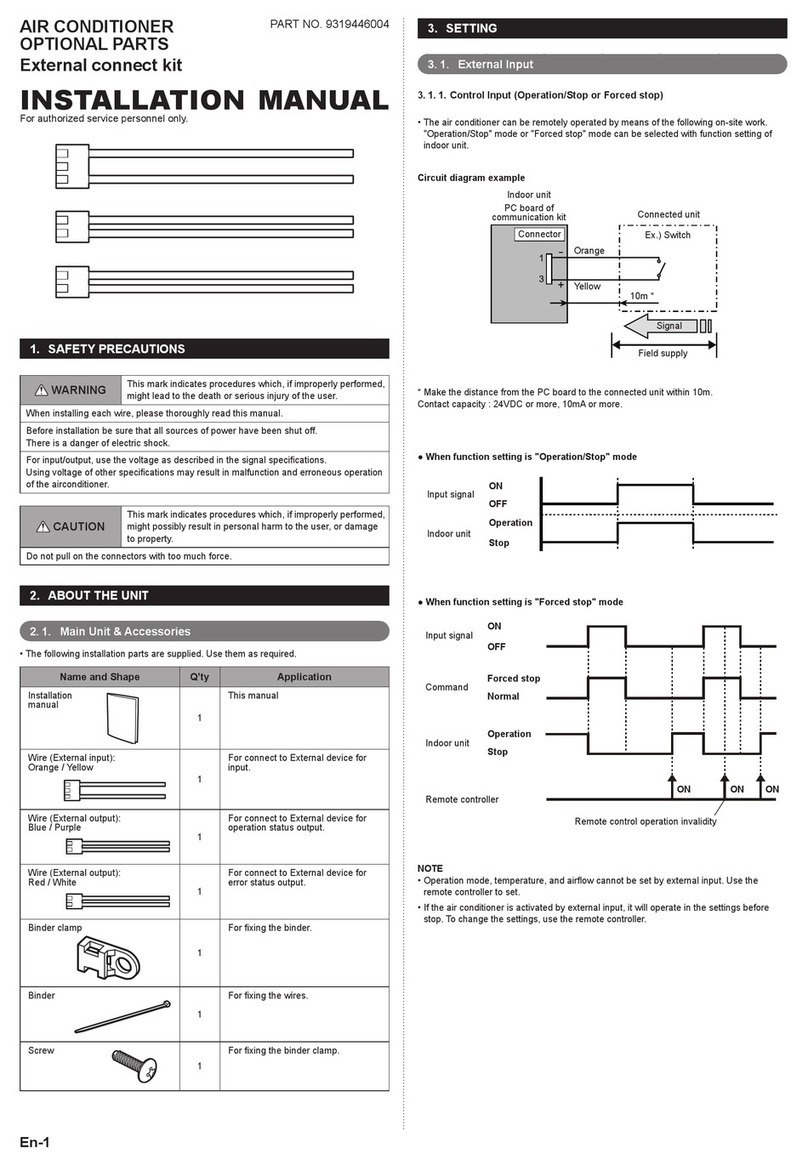
This external connect kit is an adapter for connecting the•
control PC board and the connected unit (local wiring) in
order to use external input function and external output
function of the outdoor unit.
2.2. Accessories
The following installation parts are supplied.•
Use them as required.
Contents
1. SAFETY PRECAUTIONS ................................................ 1
2. ABOUT THE UNIT ........................................................... 1
2.1. General..................................................................... 1
2.2. Accessories .............................................................. 1
3. SETTING.......................................................................... 1
3.1. Control input setting.................................................. 1
3.2. Control output setting .....................................................2
4. CONNECTION METHOD TO OUTDOOR
CONTROL PC BOARD.................................................... 3
Name and shape Q’ty Description
Installation
manual 1
This manual
Binder
2
For xing the wires.
Wire
1
For connecting to the
circuit for external input
and external output
3. SETTING
Connect the wire (External connect kit) and Connected•
unit (local wiring). Refer to the following wiring method.
3.1. Control input setting
3.1.1 Wiring of connector
Input Connector
Low noise mode CN931
External input priority mode CN932
Peak cut mode CN933
Stop operation mode CN934
* Make the distance from the PC board to the connected unit within
10m (33ft).
• Contact capacity : 24VDC or more, 10mA or more.
1
2
CN931
1
2
1
2
1
2
CN932
CN933
CN934
Circuit diagram example
Outdoor unit
control PC board Connected unit
(Field supply)
Ex.) Switch
Wire
Signal
Connector
*10 m (33ft)
English
FrançaisEspañol
9380228004-01_IM.indb 1 24/9/2553 18:20:57
En-2
3.1.2 Low noise mode (CN931)
This features reduces the operating sound of the outdoor•
unit from the normal sound. The air conditioner is set to
the “Low noise mode” when closing the contact input of a
commercial timer or ON/OFF switch to a connector on the
outdoor control PC board.
* Performance may drop depending on the outside air
temperature condition, etc.
* Set the “Low noise mode” level. Refer to the installation
manual of outdoor unit.
Input Signal ···ON : Low noise mode
···OFF : Normal operation
3.1.3 External input priority mode (CN932)
It is possible to switch to cooling operation and heating•
operation by using external input.
* Set the “External input priority mode”. Refer to the
installation manual of outdoor unit.
Input Signal ···ON : Heating operation
···OFF : Cooling operation
3.1.4 Peak cut mode (CN933)
Operation that suppressed the current value can be•
performed by means of the connected unit. The air
conditioner is set to the Peak cut mode by applying
the contact input of a commercial ON/OFF switch to a
connector on the outdoor control PC board.
* Set the “Peak cut mode” level. Refer to the installation
manual of outdoor unit.
Input Signal ···OFF : Peak cut mode
···ON : Normal operation
3.1.5 Stop operation mode (CN934)
It is possible to switch to Batch stop or Emergency stop•
and Normal operation by using external input.
* Set the “Batch stop” or “Emergency stop” pattern. Refer
to the installation manual of outdoor unit.
Input Signal ···ON : Stop operation
(Batch stop or Emergency stop)
···OFF : Normal operation
3.2. Control output setting
3.2.1 Wiring of connector
Output Connector
Error status CN951
Compressor status CN952
Make the distance from the PC board to the connected•
unit within 10m (33ft).
1) Power supply
• Voltage (Chart sign=Vcc) : DC 24V or less
2) Load
• Load : DC 500mA or less is recommended
3.2.2 Error status output (CN951)
An air conditioner error status signal is produced when a
malfunction occurs.
Input Signal
Low noise mode
ON
ON
OFF
OFF
Input Signal
Priority mode
ON
Heating
OFF
Cooling
Input Signal
Peak cut mode
ON
ON
OFF
OFF
6/4/2010   5:04:48 PM
• When function setting is “Batch stop”mode
• When function setting is “Emergency stop”mode
Input signal
Input signal
Indoor unit
Indoor unit
Remote controller
Remote controller
On
On
On On On
On
On
Off
Off
Operation
Operation
Stop
Stop
1
2
Vcc
+
+
-
Vcc
1
2
CN951
CN952
Circuit diagram example
Outdoor unit
control PC board
Connected unit
(Field supply)
Wire
Signal
*10 m (33ft)
Connector
Load
Power
supply
Error status
Output signal
Error
ON
Normal
OFF
9380228004-01_IM.indb 2 24/9/2553 18:20:58
En-3
3.2.3 Compressor status output (CN952)
Compressor operation status signal is produced when the
compressor is running.
4. CONNECTION METHOD TO
OUTDOOR CONTROL PC BOARD
Refer to below gure for the connection method to outdoor •
control PC board.
Connect the end of wire to the external circuit.•
Extend with locally purchased wire if necessary.
If extended, insulate the connected part.
Compressor status
Output signal
Operation
ON
Stop
OFF
(Example)
When connecting wire on CN931
(1) When tting the service cover, pull the cable as shown
in the diagram to prevent it from being trapped.
And x the 2 binders (accessory).
(2) Fix the Binder (accessory (outdoor unit)).
(3) Pass the cable through the as yet unused knockout hole.
(Please protect the cable with the edge of knockout hole
to avoid damage.)
Seal the knockout hole that passes the cable with putty,
so that there is no gap.



CAUTION
Do not bind this wire with other wires.•
wire
LED981
POWER
MODE
LED982
ERROR
LED961LED962
SW931
MODE
/ EXIT
SW932
SELECT
SW933
ENTER
SW934
CHECK
Control PC board
CN934 (Red)
CN933 (White)
CN932 (Green)
CN952 (Blue) CN951 (Black)
CN931 (Yellow)
For “Stop operation
mode” input
For “External input
priority mode” input
For “Peak cut mode” input
For “Compressor status” output For “Error status” output
For “Low noise mode” input
9380228004-01_IM.indb 3 24/9/2553 18:20:58
9380228004-01_IM.indb 4 24/9/2553 18:20:59

Other Fujitsu Air Conditioner Accessories manuals

Fujitsu Airstage UTY-DTGYZ1 User manual

Fujitsu

Fujitsu Airstage UTY-DTGYZ1 User manual

Fujitsu UTZ-KXRA User manual

Fujitsu

Fujitsu UTZ-KXRA User manual

Fujitsu 9319446004 User manual

Fujitsu

Fujitsu 9319446004 User manual

Fujitsu UTZ-KXGC User manual

Fujitsu

Fujitsu UTZ-KXGC User manual

Popular Air Conditioner Accessories manuals by other brands

Samsung ASSY MIM-H04UN User & installation manual

Samsung

Samsung ASSY MIM-H04UN User & installation manual

Tecnosystemi smart clima Regio user manual

Tecnosystemi

Tecnosystemi smart clima Regio user manual

GUS AUW 1 Assembly instructions

GUS

GUS AUW 1 Assembly instructions

Lennox 19V36 Installation instruction

Lennox

Lennox 19V36 Installation instruction

Trane BAYCOVR112A Installer's guide

Trane

Trane BAYCOVR112A Installer's guide

Mitsubishi Electric MSZ-RW25VG Service manual

Mitsubishi Electric

Mitsubishi Electric MSZ-RW25VG Service manual

Toshiba TCB-SIR33UP-E installation manual

Toshiba

Toshiba TCB-SIR33UP-E installation manual

GE RAKUVC1 installation instructions

GE

GE RAKUVC1 installation instructions

Midea OSK103 user manual

Midea

Midea OSK103 user manual

Tecnosystemi Smart Clima SCD500084 user manual

Tecnosystemi

Tecnosystemi Smart Clima SCD500084 user manual

Danby DPSL120B1W owner's manual

Danby

Danby DPSL120B1W owner's manual

Toro LT3240 Instruction manual & parts list

Toro

Toro LT3240 Instruction manual & parts list

Daikin RRDQ220V1 Operation manual

Daikin

Daikin RRDQ220V1 Operation manual

Hitachi E-102SN3 installation manual

Hitachi

Hitachi E-102SN3 installation manual

manuals.online logo
manuals.online logoBrands
  • About & Mission
  • Contact us
  • Privacy Policy
  • Terms and Conditions

Copyright 2025 Manuals.Online. All Rights Reserved.