IP20
EL-T E477042
NiCd/LiFePO4
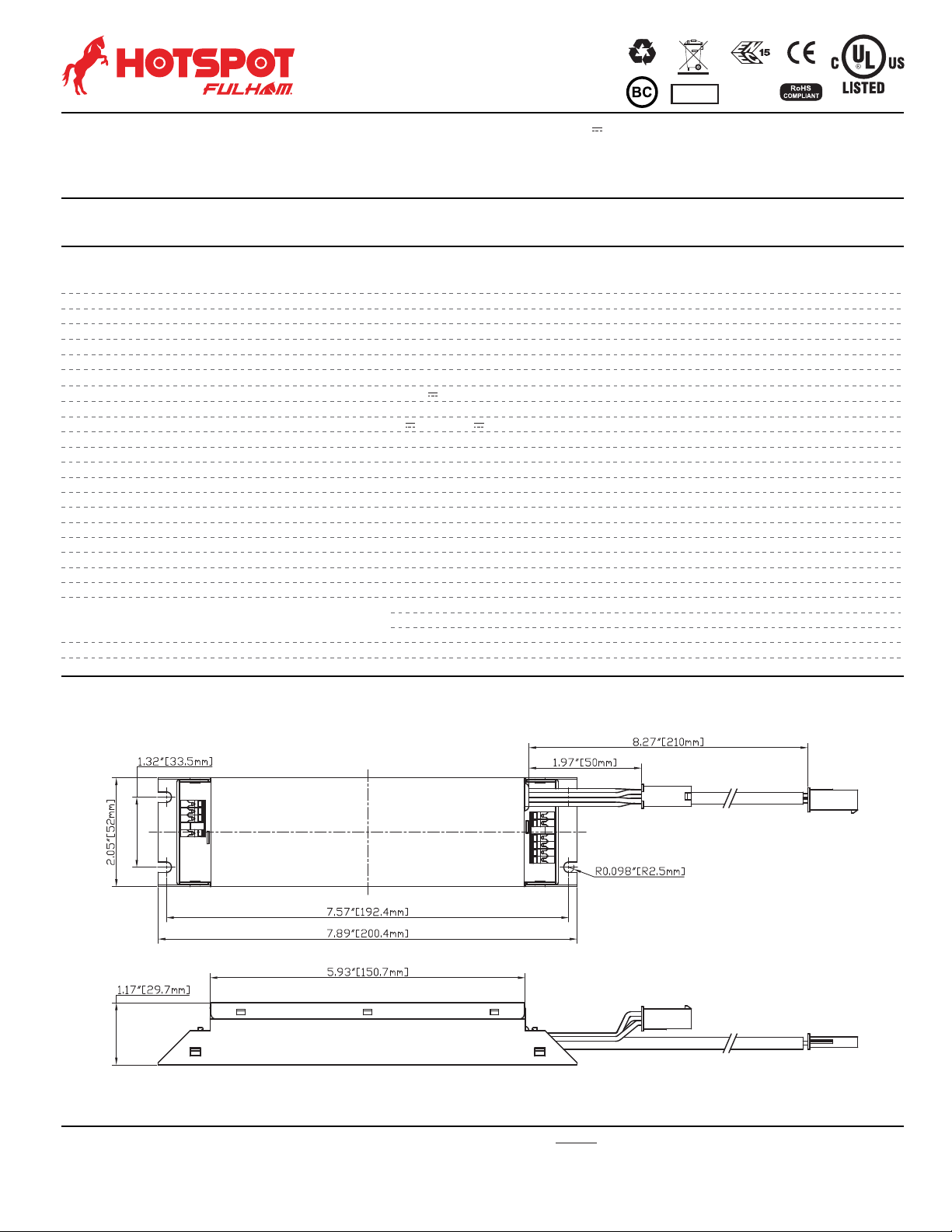
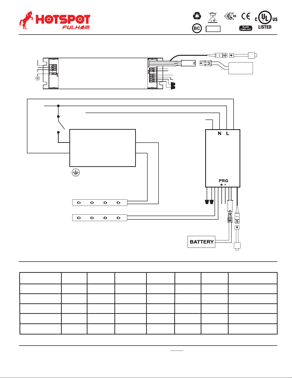
INSTALLATION INSTRUCTIONS
Fulham extends a limited warranty to the original purchaser or first user for a period of from the date of manufacture when properly installed5 years
and operated under normal conditions of use. The usage of appropriate series connected Surge Protection Device (SPD) is required in high risk
applications. For complete terms and conditions, please refer to the Warranty Center at www.fulham.com. Specifications subject to change without
notice.
Page9of10
Guideline on calculating emergency illumination level
The purpose of this guideline is to identify the illumination level of the LED luminaire when used with Fulham's
FHSCP-UNV-10P-L-SD LED emergency driver. The path of egress illumination level during emergency operation
is determined by types of luminaires, Luminaire Efficacy, Luminaire Mounting Height, Emergency Power and some
other effects in real application.
Step 1: Select an LED Luminaire, and make sure the LED light source is electrically compatible with Fulham's LED
emergency driver. Get the Light Distribution data (usually an .ies file) and Rated Efficacy data (lumen per watt)
from luminaire supplier.
If the luminaire is DesignLights ConsortiumTM (DLC) compliant, you can also get the efficacy information from
DLC website.
- Open DLC Qualified Product List(QPL) database search page: https://www.designlights.org/search/
- Searching keywords by model, brand name or manufacturer for the luminaire used.
- Find the “Efficacy” data listed on website or calculated by dividing “Light output” by “Wattage”, the efficacy
value should be shown in lumen per watt (lm/W).
If the luminaire is ENERGY STAR compliant, you can also get the luminaire efficacy information from ENERGY
STAR website.
- Open ENERGY STAR certified Light Fixtures database search page:
https://www.energystar.gov/productfinder/product/certified-light-fixtures/results
- Searching keywords by model, brand name or manufacturer for the luminaire used.
- Find the “Energy Efficiency” data listed on website. If it is showed as “Measured at the Source”, please
contact with luminaire supplier for additional light loss for this light source inside the fixture. The value should be
shown in lumen per watt (lm/W).
Step 2: Determine the Emergency Power and calculate the Emergency Light Output.
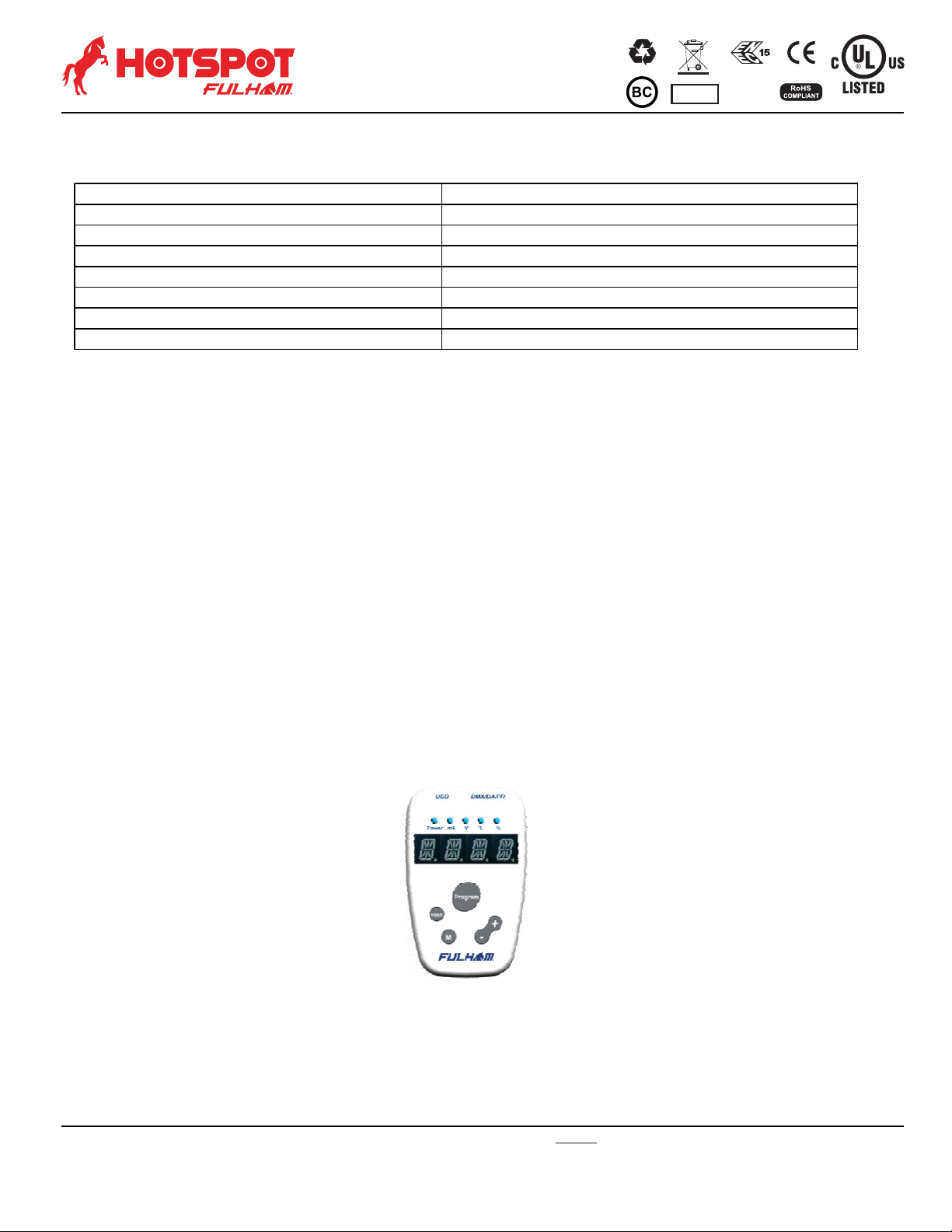
FHSCP-UNV-10P-L-SD is programmable output; setting a proper Emergency Power is vital to achieve desired
illumination.
Emergency Light Output is equal to the Emergency Power multiply by luminaire efficacy. For example, if the
luminaire is 120lm/W and in 3W emergency operation, the total Emergency Light Output is 120lm/W * 3W = 360lm.
Step 3: Use industry lighting design software to calculate the illumination level according to the luminaire layout in
room, luminaire mounting height, the original .ies file and Emergency Light Output calculated above. If the
illumination level cannot meet life safety codes, go back to Step2 to use a higher Emergency Power or go back to
Step1 to select a higher efficacy luminaire or use more luminaires in the room.
Fulham's FHSCP-UNV-10P-L-SD LED emergency driver is compliant with UL 924 standard, according to UL test
data, Table 1 and Table 2 below give basic indication to determine the min. Emergency Power and Luminaire Max.
Mounting Height for 1 foot-candle illumination based on a single luminaire with typical Lambertian distribution.
It is the light designer/ construction contractor's responsibility to validate the real illumination level on site, to assure
the emergency light illumination level is in accordance with the requirement of Federal, state and local municipal
codes. It may diff to the theoretical calculation or simulation on computer.
EM 3W EM 5W EM 10W
80 80 8.1 ft 10.1 ft 13.9 ft
100 100 8.9 ft 11.2 ft 15.4 ft
120 120 9.6 ft 12.1 ft 16.8 ft
140 140 10.3 ft 13.0 ft 18.1 ft
160 160 10.9 ft 13.9 ft 19.3 ft
180 180 11.5 ft 14.6 ft 20.4 ft
2.8 W
2.5 W
2.2 W
Table 1. Min. EM Power for 1fc @ 10ft vs. Luminaire Efficacy
Luminaire Efficacy
(lm/W)
Min. EM Power to achieve
1 fc @ 10ft Mounting Height
5.0 W
4.0 W
3.3 W
Max. Mounting Height for 1fc
Table 2. Max. Mounting Height vs. Luminaire Efficacy
Luminaire Efficacy
(lm/W)
FHSCP-UNV-10P-L-SD
2017-689-9 Rev C