FUTABA FP-3EG User manual

Futaba
DIGITAL PROPORTIONAL
RADIO CONTROL

Thank you for purchasing a Futaba digital proportional
radio control set.
Please read this manual thoroughly before using your
new
set.
CONTENTS
FEATURES
.......................1
CONTENTS
AND
RATINGS
.............2
TRANSMITTER
FP
T3EG
.............. 3
NEUTRAL
LEVER.
..................3
CONVERSION
TO SELF-NEUTRAL
........3
OPENING THE TRANSMITTERREARCOVER
AND
LOADING
THE
BATTERIES
.........4
CONVERTINGTRANSMITTERTO
NiCd SYSTEM
.....................4
SERVOREVERSING
.................5
RECEIVERFP-R3F & SERVO
............
5
RECEIVER,SERVO,& SWITCH HARNESS.
...6
THROTTLE->RUDDER
MIXING
ADJUSTMENT.
...............7
RUDDER
DUAL
RATE
................8
FPS24&
S27
EXPLODED
VIEWS.
.........9
IMPORTANT: _______________________________________________________
AN FCC CLASS C LICENSE IS REQUIREDTO OPERATETHISSYSTEM. WRITETO THE
FEDERALCOMMUNICATIONS COMMISSION AS LISTED BELOW FORAN APPLICA-
TION FORM#505.FEDERALCOMMUNICATIONSCOMMISSION
P.O.
BOX
1010
Gettysburg, PA 17325
*AII prices and specifications subject change without notice.

•FEATURES
The FP-3EG isa highquality 3 channel, expanded digital proportional radio control set.
The receiver and servo power isa four-battery;4.8V (Ni-Cad)/6.0V (Dry-Cell).The
transmitter power supply is 9.6V (Ni-Cad)/10.5V(Dry-Cell).3FG with S24 servos
only comes with Ni-cads forboth
TX
and RX.Speed and torque of our servo are the
highest inits class.
Transmitter FP-T3EG
•Rudderdual rate(dual-rateon, dual-rate
off).The desiredrudder angle can bese-
lected whendual-rateon.•Servoreversingswitch
at rudder and
nd throttlechannel.
•Throttleand rudder mixing is adjustable
upto thelimitpoint.
•Threechannel transmitter.Third channel
has a clickknoband can be conveniently
used as a subchannel.
•Throttle
lever
has
a
neutral
shift
device,
butcan be instantlychanged to a ratchet
type.
•Semi-open gimbal sticks provide maximum
feel.
•Neck band provided as standard. Com-
fortableoperationispossibleby hooking
the band aroundyourneck.
•Seven pen-cellbatterypower supply can
also bechanged to Ni-Cadbattery(NT-8C).
•Beautifulexteriorbased on human engine-
ering. Easy-to-usedesign.
Servo FP-S24
•Highest outputtorque(4.5kg-cm/62.7oz-in.
or greater)of any servoinitsclass.
•Output
gear
is
supported
at
the
top
and
bottom by ball bearingsforexcellent
neutral characteristics,long life,
and
smooth operation.
•Large 20m/m diameter coreless motor fea-
tureshigh torquenearneutraland exact
trackingof evenminute rudder movements.
•Indirectdrivesystemextendsthe life
of
the potentiometersubstantially.
•Watertight/dustproof.
Besides the FP-S24, FP-S27, watertight
servois availablewiththissystem.
1
Receiver FP-R3F
•Miniature type, light, weight,rugged con-
struction.
•Crystalisreplaceable fromthe outside.
•3P mini-connectors are compatible with
existingsets.
•3channelspecifications.
•Newlydevelopedreceiveruse FutabaCus-
tom I/C, BA633. ThisI/C is extremely
stable against power supply voltagefluctu-
ations.
•Adjacentfrequency interference is mini-
mized by the use of an RF amplifier circuit
and ceramicfilter.

•CONTENTSANDRATINGS
Setname
Transmitter
Receiver
Servo
Switch
NiCdbattery/Battholder
Others
FP-3EG
FP-T3EG x 1 Pen-cell Dry Battery Type or NiCd Battery Type.
FP-R3F x 1
FP-S24 x 2 orFP-S20x2 orS21Sx2 orS26x2 orS27x2
SWH-1
NR-4C/AA0312
Frequencyflag,neck band,horn, servotray, battery charger
(w/S24only)
Transmitter FP-T3EG
Operatingsystem
Transmitting frequency
Modulation system
Powersupply
Current drain
Receiver FP-R3F
Receivingfrequency
Intermediate frequency
Receiving range
Power requirement
Currentdrain
Dimensions
Weight
:2 sticks, 1 knob, 3
channels
:27MHzBands
72MHz Bands
:
AM
:10.5V, 7 pen-cell
batteriesor
9.6V NiCd (NT-80
:130mA
:27MHz Band
72MHz Band
:455kHz
:550 yards(500m)
on the ground
1100yards(1000m)
inthe
air
:4.8V Ni-Cad
battery
(NR-4C)or
6.0V AApen-cell
dry batteryx 4
:
6V 10mA
:1.6x7.5x2.3in.
(40.2x19.0x58.5mm)
:
1.6
oz
(46g)
Servo FP-S24
Control system
Operatingangle
Power supply
Current drain
Output torque
Dimensions
Weight
:+ pulse width
con-
trol
1310 us.N
:
One
side 45°
or
more (including
trim)
:4.8-6.0V (shared
withreceiver)
:
8mA
at
6.0V
(stopped)
:S24 62.6 oz/in.
(4.5kg/cm)
S2747.3oz/in.
(3.4kg/cm)
:S24
1.8x0.9x1.5in.
(45.4x23x38mm)
S27 1.8x0.9x1.7in.
(45.5x23x43.5mm)
:
S24
2.1
oz
(59g)
S27
1.9oz
(53g)
2

•TRANSMITTER
Thebelow figure gives thenameofeachpart
of the transmitter.
Memorize the position andoperation of each
switch and control.
33rdchannel
7Limitpoint
trimmer
6Mixing trimmer
9Throttletrim
2 Throttle
11 Power switch
5Rudder dual
ratetrimmer
4Rudder dual
rate switch
10Neutralshift
lever
3
13 Antenna
12
Handle
8Rudder trim
14Hook
Fig.1
1Rudder
Description of Fig.1
1Rudder.......Rudder operation
2Throttle ......Throttle or elevator opera-
tion
33rd channel. . . .
Needle control, etc.
4Rudder dual rate
switch
......
.Rudder
dual-rate
on/off
switch
5Rudder dual rate
trimmer ......Adjusts the amount when
the rudder dual rateswitch
isset toON. (Amountis
continuously adjustable
from 40% to 100%atdual-
rate on.)
6Mixing trimmer . .Throttle — rudder mixing
amount trimmer
7Limitpoint
trimmer .....
8Rudder trim. . .
9Throttletrim. .
10 Neutral shift lever
......
11
Powerswitc h
2Handle
1
3Antenna
14
Hook
......
.Changes the mixing amount
limit at throttle-<rudder
mixing.
.Rudder fineadjustment.
.Throttlefineadjustment.
.Changes the neutral posi-
tionofthethrottlecontrol
stickin5 steps.
.Theaccessory neck band
hooks tothishook.
Neutral Lever Operation Conversion from Self-Neutral System to
Thestick lever neutral
position can be adjust-
edin5 stepsby moving
the leveras shown in
the figure.
Fig.
2
Remove the
spring and
swing arm.
Twistwithneedle
nose pliers,etc.
Fig.
3
ratchet System
Install the slide plate.

•OPENINGTHETRANSMITTERREAR
COVERANDLOADINGTHEPENLIGHT
BATTERIES
•Remove the rear cover of the transmitter as
shown in Fig. 4 and load the7 pen-cell bat-
teriesin thecorrectpolarity.
Paycareful attention to the
polarity
yy
of the 7 pen-cell batteries.
Wrap rubber bands around the
batteriestohold them inplace.
•Extendthe antenna fullyand set the POWER
switchtoON. The meter pointer should de-
flectto thegreen zone. Ifthemeter pointer
does notmove, or moves verylittle,check for
poor batterycontact,incorrectbattery polar-
ity, or faultybatteries.
Charging the
FP-T3EG NiCd.
Insert the charger
and TXplug into
thecharging jack
on the side of the
transmitter.
The charging LED
atthe TXlights to
indicate thatthe
battery isbeing
charged.
Fig.
6(B)
•When the meter pointer entersthe red zone,
the range of theradio waves will become
short.Change the batterieswhen themeter
pointer drops to the boundary between the
red and green zones.
•Usethe trimlever to fine adjust each rudder.
This lever can also beused toadjusttheneu-
tralposition and the flightposture afterthe
mechanism hasbeen mounted. However, after
testflight,alladjustments shouldbemade
with the rod adjusters,etc. and the lever
handle should beleftinthe neutral position
asmuchaspossible.
Fig.
6
(A)
•The throttlestickneutralpositioncan be
selectedin 5 steps bymoving the neutral lever
as shown inFig. 2.
Converting thetransmitter
toa NiCdsystem
Adjustthe neutral position to matchthe ap-
plication.
•WiththeNiCd systemFP-T3EG,recharge the
batteryas showninFig. 6(B).
The NT-8C is alreadyinstalled.
Remove the charging
socket blindcover.
•To change the elevator stickfrom a self-
neutral typetoa ratchettype,install theslide
plate and remove the spring and stick arm as
shown inFig. 3.
•Use the NT-8C transmitter
NiCd battery sold separately
4

•REVERSINGTHESERVO
Fig.
7
After connecting the linkage, check each rudder.
If the directionof the rudder and the stickoperating
directionareopposite, switchthe reversingswitch.
15Rudder reverseswitch
16 Throttlereverse switch
15Rudderreverse switch (Reverses the direction
of operation of the rudder servo.)
16
Throttle
reverse
switch
(Reverses
the
direction,
of operationof the throttle servo.)
•RECEIVERFP-R3FandSERVO
FP-S24 5
•Plug the charge (FBC-1orFBC-2A optional)
into a 110V outletand connect the 3Pcon-
nector of the charger to the receiver/servo
NR-4CNiCd batterypack asshown in Fig. 8.
The LED on the chargerwilllight to indicate
that theNiCd batteryis charging.
•The
NiCd battery
pack
can
be
used
about
12 timesat10minutes/time.
•Alwaysrecharge thebatterybeforeuse.
•The chargingtimeisabout12~15hours
•Withthe batterysystem,insert the four
dry-cellbatteries,being surethatthe polar-
ity is correct,then firmlytightenthe coin
screw.
•Connect the servo and switch as shown
in
Fig. 9.Then extendthe transmitter
and
re-
ceiverantennasfully.
•Setthe transmitterPOWERswitch
to ON,
then set the receiverPOWERswitchto ON.
The servowillstop near theneutral
posi-
tion.
Operate each stick of the transmitterand
checkthatthe correspondingservofaith-
fullyfollowsthe movement of the stick.
•Set
the pushrod at
each
servo
horn,
then
check that the directionof servomatches
the directionof transmitterstick.
•Operate each servohorn overits entire
operatingrangeand check ifthe pushrod is
too tight or too loose.
Applying unreasonableforceto the servo
horn willadverselyaffectthe servo and
quicklydrainthe batteries.
Alwaysmake the operatingwidthof each
rudder somewhat largerthanthe full
stroke (including trim)of the servo horn.
Adjust the servohorns so thattheyoper-
ate smoothlyevenwhen the trimleverand
stickleverareoperated simultaneously in
the same direction.

Fig.
9
•Be alert for noise.
If engine vibrationcauses metal partsto
touch, noise willbe produced and there-
ceiverand servosmay operateincorrectly.
We recommend theuse ofnoiselessparts.
•When installingthe switch,cut a rectangu-
lar holesomewhatlargerthanfullstroke
of theswitchand installtheswitchso that
itmoves smoothlyfromON toOFF.When
the switch is mounted inside the fuselage
and is turnedON-OFFwithwire,install
the switchmount in thesame manner.
Installthe switchwhereitwillnot come
into direct contact with the engine oil,
dust,etc.
•Eventhough the receiverantenna islong,
do not cut or bundle it.
•Installthe servofirmly.Refer to Pig. 10at
the right.
•Aspareservohorn is supplied. Use itas
needed. Do not forgetto installthetooth
washerwhen changingthehorn.
•Wrapthereceiverinsponge rubber. Place
the receiver ina plastic bag and wrapa
rubber band around theopen end of the
bag to waterproofand dustproofthe re-
ceiver.
Do
the
same
with
the
receiver bat-
tery.
•Also usethe rubber bands wrappedaround
the receiver to hold the servoand switch
leads.
•Aftermounting is complete, recheckeach
part, then make thetransmitterantenna as
short as possible,extendthereceiveran-
tennafully,and operatethe set froma dis-
tanceof 22 to 33 yards(20to 30m) for
range check.The movement of each servo
should followthe operation of each stick
of the transmitter.
6

•THROTTLE->RUDDER MIXING
ADJUSTMENT
The rudder neutralposition at engine SLOW
and engine HIGH depends on the engine
torque.When adjustedforstraightahead
when a common 2-cycleglow plug engine is
at HIGH,the boat willslowlyswerveto the
leftat SLOW and ifadjusted forstraight
ahead when the engine is at SLOW, the boat.
willslowlyswerveto theright at HIGH. Mix-
ingfromthrottleto rudder, thebiggest
featureof the Model FP-3EG, completely
eliminates this tendency.
The followingdescriptionis fora common 2-
cycleglow plug engine thatrotatescounter-
clockwise.Reversethedescriptionfora gasoline
engine, electricmotor, etc. that rotatesclock-
wise.
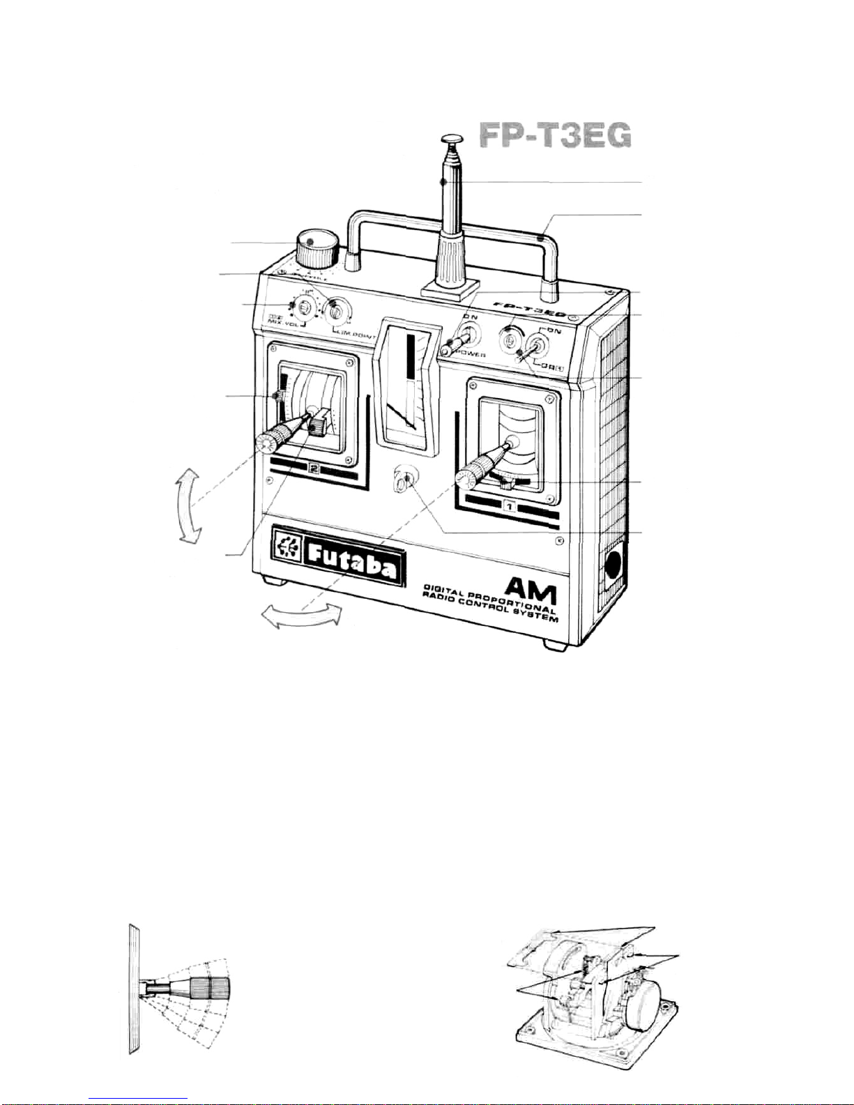
Thismixingis adjustedwiththemixing
trimmer and limit point trimmer at theleft
front of the transmitter.
Mixingtrimmer6 adjuststheamount and
directionofmovementofthe rudder servo
when the throttlestickis moved upand
down. The mixing amount is zeroat the
center position.
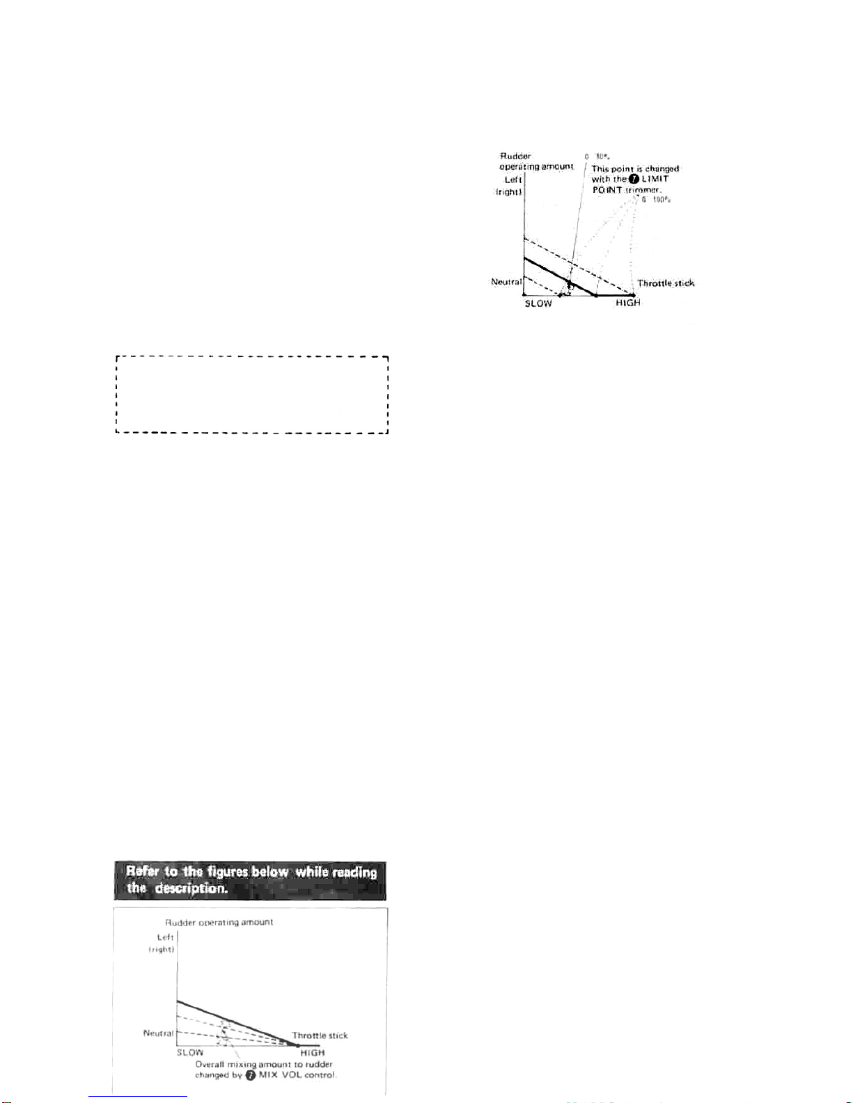
Limit point trimmer7 changes the point at
which theoperatinglineofthe mixing
amount totherudder servocurveswhen the
throttlestickismoved fromLOW toHIGH.
1When the throttlestickis set to HIGH, a
boat movingstraightat enginecontrol
SLOW willswerveto the right.On the
other hand, a boat moving straightahead
at throttleHIGH willswerveto theleft
when the throttlestickisset to SLOW.
That is, therudder servoshouldbe turned
tothe right when thethrottlestickisset
to SLOW.
2Turn the mixingtrimmer witha screw-
driverso thattherudder turnsslightlyto
the rightwhen thethrottlestick ismoved
fromHIGH to SLOW.
You should now have a good understanding
of throttletorudder mixing.
Throttle->rudder mixing will becalled
"MIX" hereafter.
3
•Run the boat without MIX (MIX trimmer
at center)and check therudder neutral,
play,and engine SLOW and HIGH.
•Limit point
Turn the trimmer about
2/3 clockwise.
(Inthe L to H direction.)
•Under
this
state,
turnthe MIXtrimmer
about halfwayinthe R (right)direction
and check the rudder movement (rudder
servo)whilemoving the throttlestickup
and down. The rudder shouldmovea little
to theright atSLOW and a little tothe left
at HIGH.
•Set
the
MIX
trimmer
to
zero (center) at
throttlestickHIGH. The rudder servo
should not move because themixing
amount is zero at throttle HIGH as shown
in
Fig. 11.
4Afterall preparations are complete, make
adjustments whileactuallyrunning.
AAdjusttherudder trimmerso thatthe
boat travelsstraightahead at throttle
HIGH.
BSet the throttle stick to SLOW. Ifthe
boat
swerves
to
the right
at
this
time,
the
MIXamount isexcessive.Reduce the
MIX amount by turningtheMIXtrimmer
toward the center.If the boat slowly
swerves to the left,the MIX amount is in-
sufficient.Increasethe MIX amount by
turningtheMIX trimmerinthe R direc-
tion.
CThis completes MIXadjustment at throt-
tle SLOW and HIGH. However,adjust-
ment near medium SLOW isstillneces-
sary.To adjustnear medium SLOW,
proceedas follows:
7

(a) Ifthe boat slowlyswervesto the right
when the throttlestickisset tomedi-
umSLOW, thePOINT istoo high.
Adjustitby turningthe limit point
trimmer counterclockwise. Then re-
adjustitem B above.
(b)Ifthe boat slowlyswerves
to the left,
the POINT is too low. Adjustby turn-
ingthe limit point trimmerclockwise.
Then readjust the MIXtrimmer as
described initem
(B).
RUDDER DUAL RATE(DUAL-RATEON,
DUAL-RATEOFF)
•Rudderdualrateswitch
Dual-rate(servostrokebecomes narrow)is
effectedwhenthisswitchisset toON.
Dual-rateis offwhenthe switch isset to
OFF.OFFis the normal state.
•Rudder dual ratetrimmer
Thistrimmeradjuststhe fullstrokeofthe
servowhen therudder dual rateswitchis
set to ON. Adjustit to match thecourse
and technique. The rudder dual rate
amount is continuously variablefrom40%
to
100%.
•The
Futaba
Mini
3-pin
wireservo can
be
combined withany Futaba transmitterand
receiver.Use itto match the application.
(However,exceptthe FutabaJ Module
Series.)
•Aftermountingand checking are complete,
take your model to the storewhereyou
purchased the digitalproportionalset, or
to an experiencedradiocontrolenthusiast,
and ask them to tellyou how to install
your radiocontrolset correctlyand to in-
spect your set-up carefully.
Futaba
DigitalProportionalFrequencies
Band
Band
Band
Band
Band
(1)
(2)
(3)
(4)
(5)
•
*
*
•
*
26.995MHz
27.045MHz
27.095MHz
27.145MHz
27.195MHz
72.080MHz
72.160MHz
72.240MHz
72.320MHz
72.400MHz
72.960MHz
75.640MHz
Aircraftuseonly.
Brown
Red
Orange
Yellow
Green
Brown/White
Blue/White
Red/White
Violet/White
Orange/White
Yellow/White
Green/White
The frequency of Futaba digital pro-
portionalsetscan be changed among
bands (1)~(5)on the 27MHzband
only.
However, a 27MHz band set cannot be
changed to 72MHz band, and vice
versa.
Therefore,always attach the correct
frequency flagto the end of the
transmitterantenna. Each frequency
band has itsown designated color,as
statedabove.. The frequencyflagisin-
tended foridentificationpurposes.
Also change the frequency flagwhen
changing the crystal.
Futabapairedcrystalsare precisely
matched. Alwaysuse a Futabacrystal
set (transmitter,receiver) when chang-
ingthe frequency.
Itis illegalto change crystalsof trans-
mitteron the72-76MHz bands inthe
U.S.A.
FACTORY REPAIR SERVICE
To insurepromptservice, please followthe instructions given below.
1.Chargethe batteries for at least18hourspriorto shipment.
2. Return the systemonly.
Notyour complete installation. Remove the servos from their mounts and remove the foam
padding fromthe receiver.
3.Plugsorothermodifications which interfere with factory testprocedureswillbereturned to factory standard at
your expense.
4.Carefully pack all components individually, usingsufficient packing material to prevent damageduringshipment.
5.Includea brief
butthorough explanation of all problems and service required andtapeitto the backofthetrans-
mitter. Place a labeldescribing the functionof the servo on each servo.
6.Be sureto include yourfulladdress and tel.No.,zipcode in»idethe box as well as on the outside.
7.Includea packing list of all items beingreturned, and double check to make sure that allitems are packed.
8.Upon receipt of your equipment at the Futaba factory,an estimateof the cost of repair (over $25.00 only)will be
sent toyou.Your equipment willthen berepaired and returnedto you upon receiptofpayment or C.O.D. (cash).
ThisfactoryrepairserviceappliesonlytothecontinentalU.S.A.,Hawaii,andAlaska.

FP-S24
9

This manual suits for next models
3
Table of contents
Other FUTABA Remote Control manuals

FUTABA
FUTABA 6J User manual

FUTABA
FUTABA CONQUEST User manual

FUTABA
FUTABA T18MZ User manual

FUTABA
FUTABA ATTACK_III User manual

FUTABA
FUTABA 16IZ Use and care manual

FUTABA
FUTABA AZPT14SG-24G User manual

FUTABA
FUTABA 12FG User manual

FUTABA
FUTABA FP-2GS User manual

FUTABA
FUTABA ATTACK_SPORT User manual

FUTABA
FUTABA FX-36 Mounting instructions

FUTABA
FUTABA GYA460 User manual

FUTABA
FUTABA MAGNUM SPORT FP-2P User manual

FUTABA
FUTABA FP-2E User manual

FUTABA
FUTABA ATTACK-4 User manual

FUTABA
FUTABA T18SZ User manual

FUTABA
FUTABA 4YWD User manual

FUTABA
FUTABA FP-8SSHP User manual

FUTABA
FUTABA T32MZ Manual

FUTABA
FUTABA 6EX 2.4GHZ Owner's manual

FUTABA
FUTABA 2PH User manual