Gainsborough G+ Series User manual

G+ VIDEO ENTRY
User Guide

WELCOME TO
THE EASIER WAY
TO ACCESS
YOUR HOME

This guide will show you how to install your
G+ Video Entry Box.
CONTENTS
SECTION 1
Overview............................................................................................................................2
G+ Camera 2
G+ Home Port 3
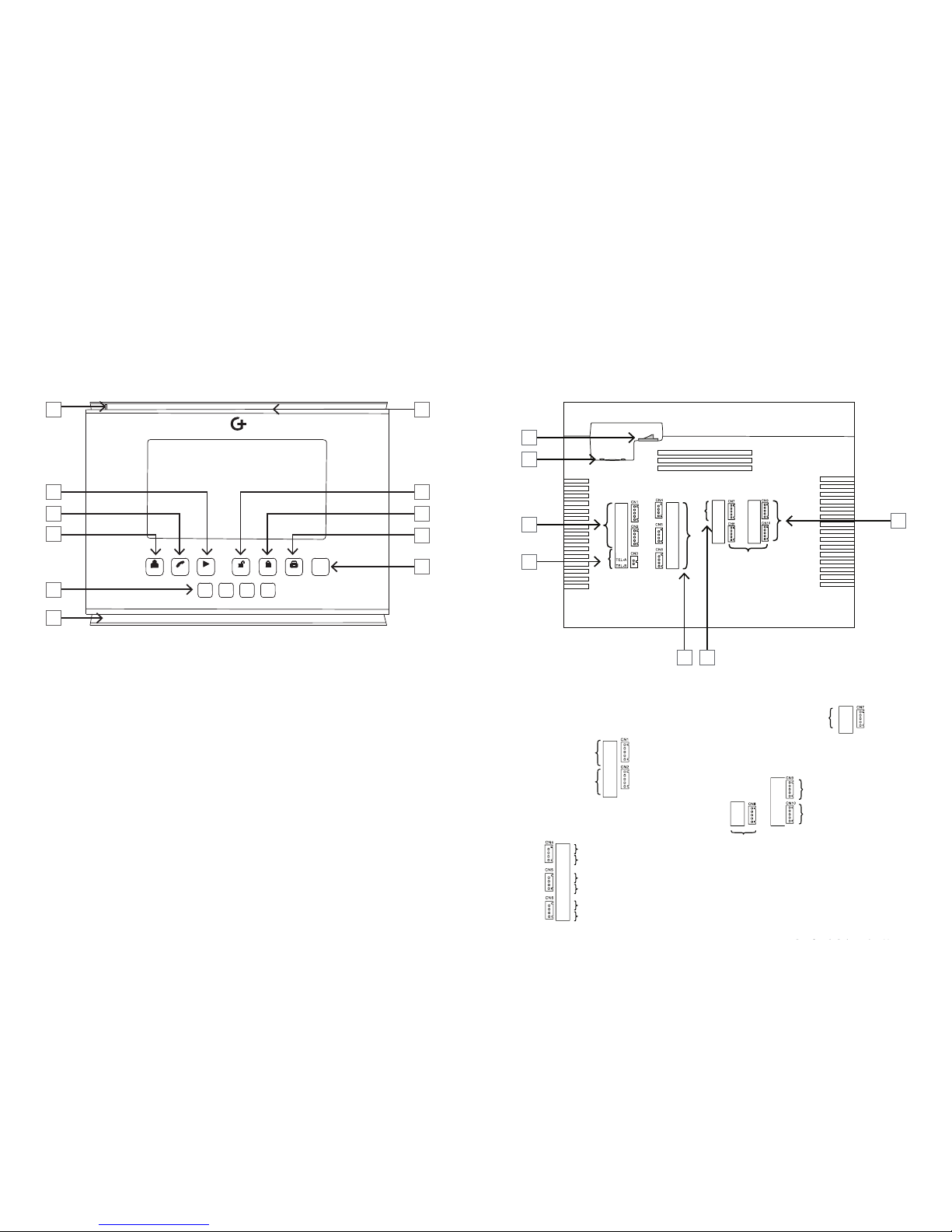
G+ Internal Display Unit: Vista Model 4
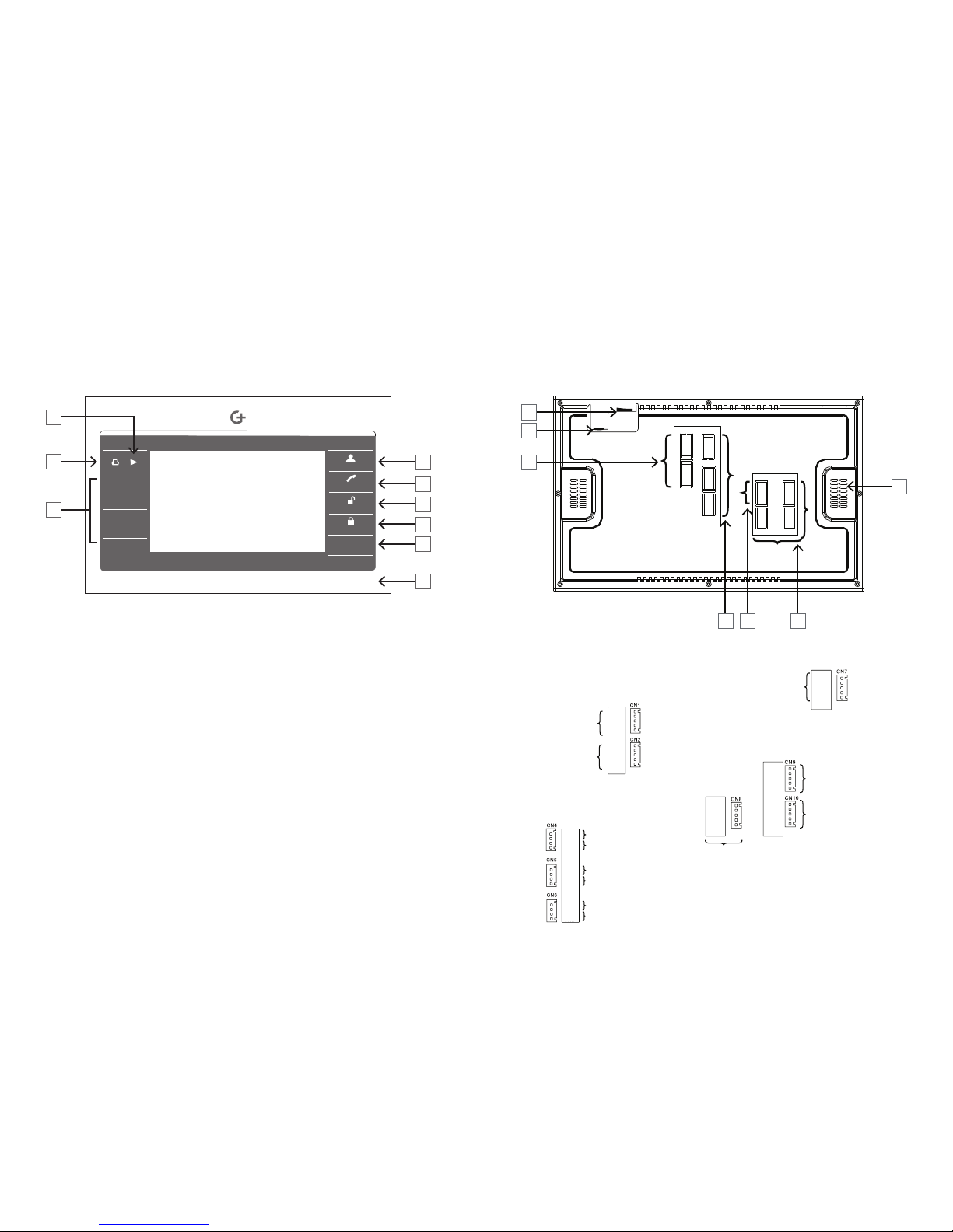
G+ Internal Display Unit: Horizon Model 6
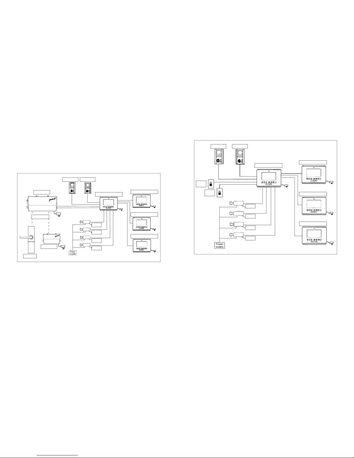
System Layout ................................................................................................................8
Connections when controlling a G+ Lockset / G+ Smart Boxes 8
Connections when wiring directly to an electric strike 9
SECTION 2
Installation ............................................................................................................12
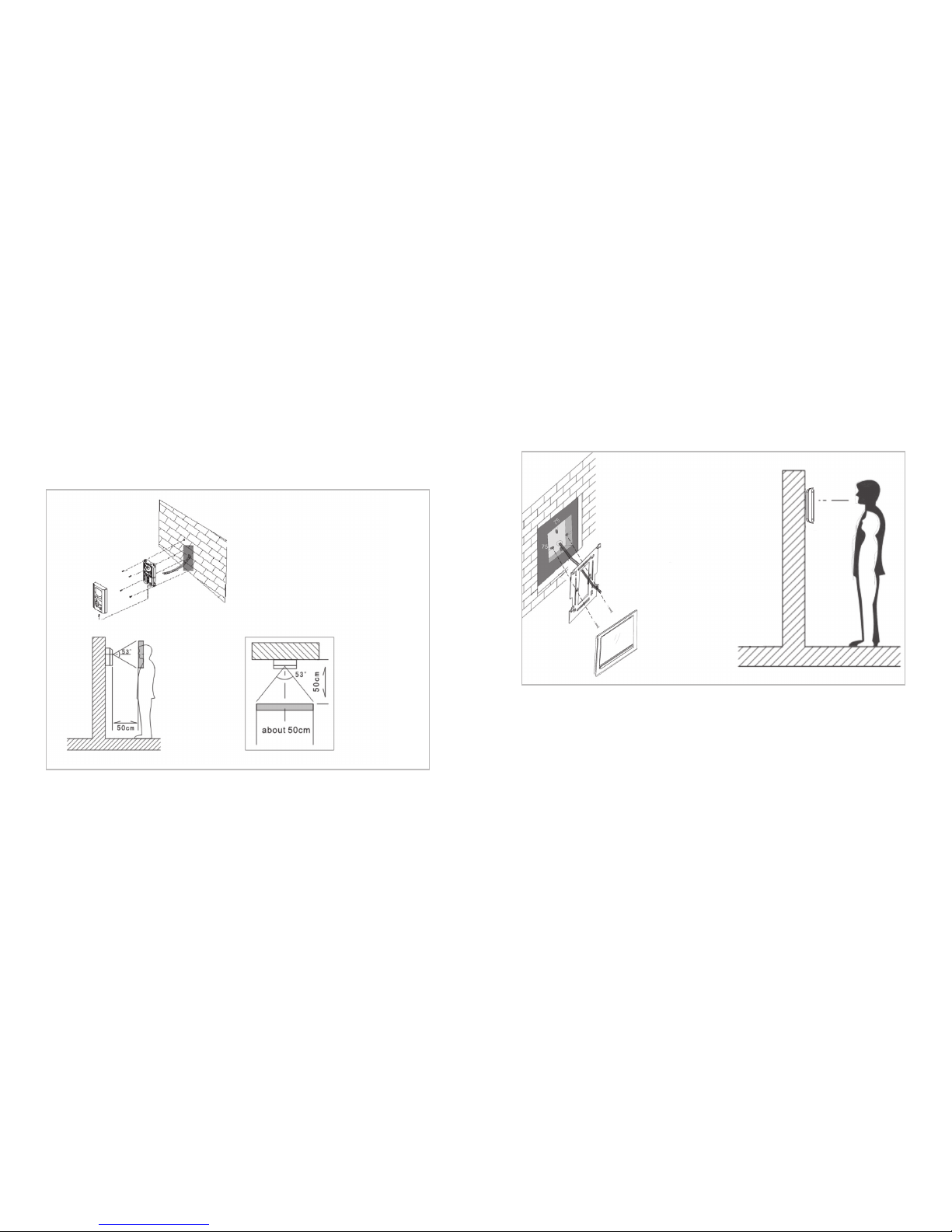
G+ Camera installation 12
G+ Internal Display Unit installation 13
G+ Home Port installation 13
Wiring Instructions Guidelines...............................................................................14
Controlling a G+ Lockset / Smart Box from the G+ Video entry 14
Controlling an Electric Strike from the G+ Internal Display Unit:
recommended method 15
Controlling an Electric Strike from the G+ Internal Display Unit:
alternative method 16
Wiring diagram for multiple G+ Internal Display Units 17
Wiring using Cat5e Cable 18
Set Up ..............................................................................................................................20
Home Port, G+ Video Entry 20
Multiple G+ Internal Display Unit Set up, Chime Settings 21
Volume Settings, Other Settings 22
How to answer a call from G+ Internal Display Unit and
unlock/lock the door 23
How to transfer a visitor’s call between G+ Display Units 24
How to adjust brightness/contrast/colour 24
How to monitor the cameras 25
How to make calls between G+ Internal Display Units 26
How to broadcast to all the other G+ Internal Display Units 26
How to set a G+ Internal Display Unit to “Do Not Disturb” 27
Indicator Light Status 27
SECTION 3
General Specifications .............................................................................................30
G+ VIDEO ENTRY G+ INTERNAL DISPLAY UNIT
VISTA MODEL
OR
G+ INTERNAL DISPLAY UNIT
HORIZON MODEL
WHAT’S IN YOUR G+ VIDEO ENTRY BOX?
This appliance is not intended for use by persons (including children)
with reduced physical, sensory or mental capabilities, or lack of experience
and knowledge, unless they have been given supervision or instruction
concerning use of the appliance by a person responsible for their safety.
Children should be supervised to ensure that they do not play with
the appliance.
Take care! electricity kills. Switches, power outlets and other fixed wire
products must be installed by a licensed electrical contractor or similarly
qualified person.
1 2
3 4
Room Room
Room Room
Menu/Set Next/+ Monitor
Answer
Intercom
Passage
Privacy
Off/Save
OK
1 2 3 4
Room Room Room Room
Passage Privacy
Menu/Set
Off/Save
OK
Next/+
Answer
Intercom
Monitor

1
OVERVIEW,
SYSTEM LAYOUT

32 Section 1 Overview
Overview
The G+ Video Entry allows:
• Visitors to communicate with occupants of the building from
the G+ Camera
• The occupants of the building to monitor, via a G+ Internal
Display Unit, who is at the G+ Camera or CCTV Cameras
• The occupants to control access to the building via:
– A G+ Lockset
OR
– Up to 2 G+ Smart Boxes
OR
– Direct wiring to an Electric Strike or similar.
• The G+ Video Entry allows for up to:
– 2 G+ Cameras
– 4 CCTV Cameras
– 4 G+ Internal Display Units.
1 Camera
2 Night Vision
LEDs
3 Microphone
4 Name Plate
5 Speaker
6 Call Button
7 Screw Holes
8 Cable Terminals
9 Face Plate /
Main Body
Securing Screw
PWR GND VD AU KEY1 KEY2
G+ CAMERA
17
8
9
2
3
4
5
6
PWR GND VD AU KEY1 KEY2
Section 1 Overview
Teach –
Lockset
Teach –
Smart Box 3
Remove device
Teach Indicator
Programming
Connector
Teach –
Smart Box 1
Teach –
Smart Box 2
Input 1 –
Smart Box 1
Power
Input 2 –
Smart Box 2 /
Lockset Privacy
Input 3 –
Smart Box 3 /
Lockset Passage
G+ HOME PORT

5Section 1 Subsection Name4Section 1 Subsection Name
Back
1 2 3 4
Room Room Room Room
Passage Privacy
Menu/Set
Off/Save
OK
Next/+
Answer
Intercom
Monitor
G+ INTERNAL DISPLAY UNIT: VISTA MODEL
1 Indicator Light
2 Menu Item Change
3 Answer Incoming Calls /Transfer Calls to other G+ Internal Display Units
4 Monitor / Select Cameras
5 Room Call
6 Speaker
7 Microphone
8 Passage Mode for G+ Lockset, or, Activate G+ Smart Box 1,
or Unlock for G+ Camera 1
9 Privacy Mode for G+ Lockset, or, Activate G+ Smart Box 2,
or Unlock for G+ Camera 2
10 Menu Navigation
11 Stand By Mode / Menu Save & Exit
Front
1 7
8
9
10
11
2
3
4
5
6
Section 1 Overview Section 1 Overview
Section 1 Subsection Name
12 Power ON/OFF
13 Power DC 18V Input
14 Input Connectors for
G+ Cameras
15 Not Used
16 Input Connectors for CCTVs
17 Input Connector
(G+ Internal Display Units 2,3,4)
18 Output Connectors
(G+ Internal Display Unit 1)
12
13
14 18
15
16 17
G+ Camera 1
G+ Camera 2
CCTV 1 Video
CCTV 2 Video
CCTV 3 Video
CCTV 1 Audio
CCTV 2 Audio
CCTV 4 Video
Input from
G+ Internal Display Unit 1
Output to
G+ Internal Display Unit 3
Output to
G+ Internal Display Unit 2
Refer to wiring diagrams for more information.
Output to
G+ Internal Display Unit 4
DA
GND
S-AD1
S-VD1
VG
DA
GND
S-AD1
S-VD1
VG
DA
GND
S-AD3
S-VD3
VG
DA
GND
S-AD4
S-VD4
VG
DA
GND
S-AD2
S-VD2
VG
DA
GND
S-AD3
S-VD3
VG
DA
GND
S-AD4
S-VD4
VG
DA
GND
S-AD2
S-VD2
VG
VD3
VG
AD3
GND
VD4
VG
AD4
GND
VD5
VG
AD6
VG
VD3
VG
AD3
GND
VD4
VG
AD4
GND
VD5
VG
AD6
VG
PWR2
GND
AD2
VD2
LCK2
PWR1
GND
AD1
VD1
LCK1
PWR2
GND
AD2
VD2
LCK2
PWR1
GND
AD1
VD1
LCK1

76 Section 1 Overview
Front
1 2
3 4
Room Room
Room Room
Menu/Set Next/+ Monitor
Answer
Intercom
Passage
Privacy
Off/Save
OK
1 Menu Item Change
2 Menu Navigation
3 Room Call
4 Monitor / Select Cameras
5 Answer Incoming Calls / Transfer Calls to other G+ Internal Display Units
6 Passage Mode for G+ Lockset, or, Activate G+ Smart Box 1,
or Unlock for G+ Camera 1
7 Privacy Mode for G+ Lockset, or, Activate G+ Smart Box 2,
or Unlock for G+ Camera 2
8 Stand By Mode / Menu Save & Exit
9 Microphone
1
4
5
6
7
8
9
2
3
G+ INTERNAL DISPLAY UNIT: HORIZON MODEL
Section 1 Overview
Back
10
11
12
13 14 15
16
10 Power ON/OFF
11 DC 18V Input
12 Input Connectors
for G+ Cameras
13 Input Connectors
for CCTVs
14 Input Connector
(G+Internal Display Units 2,3,4)
15 Output Connectors
(G+Internal Display Unit 1)
16 Speaker
G+ Camera 1
G+ Camera 2
CCTV 1 Video
CCTV 2 Video
CCTV 3 Video
CCTV 1 Audio
CCTV 2 Audio
CCTV 4 Video
Output to
G+ Internal Display Unit 3
Output to
G+ Internal Display Unit 2
Output to
G+ Internal Display Unit 4
Input from
G+ Internal Display Unit 1
Refer to wiring diagrams for more information.
DA
GND
S-AD1
S-VD1
VG
DA
GND
S-AD3
S-VD3
VG
DA
GND
S-AD4
S-VD4
VG
DA
GND
S-AD2
S-VD2
VG
VD3
VG
AD3
GND
VD4
VG
AD4
GND
VD5
VG
AD6
VG
PWR2
GND
AD2
VD2
LCK2
PWR1
GND
AD1
VD1
LCK1

98 Section 1 System Layout
CONNECTIONS WHEN CONTROLLING A G+ LOCKSET /
G+ SMART BOXES
System Layout
1 2 3 4
Room Room Room Room
Passage Privacy
Menu/Set
Off/Save
OK
Next/+
Answer
Intercom
Monitor
1 2 3 4
Room Room Room Room
Passage Privacy
Menu/Set
Off/Save
OK
Next/+
Answer
Intercom
Monitor
1 2 3 4
Room Room Room Room
Passage Privacy
Menu/Set
Off/Save
OK
Next/+
Answer
Intercom
Monitor
1 2 3 4
Room Room Room Room
Passage Privacy
Menu/Set
Off/Save
OK
Next/+
Answer
Intercom
Monitor
Vista Model G+ Internal Display Unit shown.
Wiring for the Horizon Model G+ Internal Display Unit is the same.
G+ Internal Display Unit 1
G+ Camera 2G+ Camera 1
G+ Home Port
RF Transmission
G+ Lockset
G+ Smart Box
G+ Internal Display Unit 2
CCTV 1
CCTV 2
CCTV 3
CCTV 4
G+ Internal Display Unit 3
G+ Internal Display Unit 4
Section 1 System Layout
CONNECTIONS WHEN WIRING DIRECTLY
TO AN ELECTRIC STRIKE
1 2 3 4
Room Room Room Room
Passage Privacy
Menu/Set
Off/Save
OK
Next/+
Answer
Intercom
Monitor
1 2 3 4
Room Room Room Room
Passage Privacy
Menu/Set
Off/Save
OK
Next/+
Answer
Intercom
Monitor
1 2 3 4
Room Room Room Room
Passage Privacy
Menu/Set
Off/Save
OK
Next/+
Answer
Intercom
Monitor
1 2 3 4
Room Room Room Room
Passage Privacy
Menu/Set
Off/Save
OK
Next/+
Answer
Intercom
Monitor
Vista Model G+ Internal Display Unit shown.
Wiring for the Horizon Model G+ Internal Display Unit is the same.
G+ Internal Display Unit 1
G+ Camera 2G+ Camera 1
Electric
Strike 1
Electric
Strike 2
G+ Internal Display Unit 2
CCTV 1
CCTV 2
CCTV 3
CCTV 4
G+ Internal Display Unit 3
G+ Internal Display Unit 4

2
INSTALLATION,
SET UP, OPERATION

1312 Section 2 Installation
Installation
G+ CAMERA INSTALLATION
Step 1: The G+ Camera should be installed at eye height as shown below.
Step 2: Direct sunlight and rain on the camera should be avoided.
Section 2 Installation
G+ INTERNAL DISPLAY UNIT INSTALLATION
Step 1: The G+ Internal Display Unit should be installed at eye height as
shown below.
Step 2: Fix the monitor bracket to the wall as shown then run the cable
through the bracket.
Step 3: Install the G+ Internal Display Unit on the wall as shown.
G+ HOME PORT INSTALLATION
Refer to the G+ Home Port Manual for Installation Guidelines.

1514
CONTROLLING A G+ LOCKSET / SMART BOX FROM
THE G+ VIDEO ENTRY
Wiring Instructions Guidelines
TAKE CARE - ELECTRICITY KILLS!
Switches, power outlets and other fixed wired products must be installed
by a licensed electrical contractor or similarly qualified person.
NOTE: The installer should consider strain relief for all cables.
Section 2 Wiring
CONTROLLING AN ELECTRIC STRIKE FROM THE
G+ INTERNAL DISPLAY UNIT: RECOMMENDED METHOD
NOTE: The Electric Strike will be operated by the G+ Internal Display Unit’s
Power Supply. Refer to the General Specifications section for the Electric
Strike Voltage Output for the Vista and Horizon Internal Display Units.
NOTE: The installer is responsible for ensuring the compatibility / suitability
of Electric Strikes connected to the G+ Internal Display Unit
Section 2 Wiring
Electric Strike 1 is operated by the Passage Button.
G+ Camera 1
G+ Internal Display Unit 1
G+ Home Port
DA
GND
S-AD1
S-VD1
VG
DA
GND
S-AD3
S-VD3
VG
DA
GND
S-AD4
S-VD4
VG
DA
GND
S-AD2
S-VD2
VG
VD3
VG
AD3
GND
VD4
VG
AD4
GND
VD5
VG
AD6
VG
PWR2
GND
AD2
VD2
LCK2
PWR1
GND
AD1
VD1
LCK1
G+ Home Port
G+ Internal
Display Unit 1
G+ Camera 1
G+ Internal
Display Unit 1
G+ Camera 1 Electric strike 1
DA
GND
S-AD1
S-VD1
VG
DA
GND
S-AD3
S-VD3
VG
DA
GND
S-AD4
S-VD4
VG
DA
GND
S-AD2
S-VD2
VG
VD3
VG
AD3
GND
VD4
VG
AD4
GND
VD5
VG
AD6
VG
PWR2
GND
AD2
VD2
LCK2
PWR1
GND
AD1
VD1
LCK1

1716 Section 2 Wiring
CONTROLLING AN ELECTRIC STRIKE FROM
THE G+ CAMERA: ALTERNATIVE METHOD
NOTE: The installer is responsible for ensuring the compatibility / suitability
of Electric Strikes being connected to the G+ Camera.
WARNING: This method of wiring the Electric Strike is not secure.
Removing the G+ Camera allows access to the wires that activate the
Electric Strike.
Electric Strike 1 is operated by the Passage Button.
Section 2 Wiring
WIRING DIAGRAM FOR MULTIPLE
G+ INTERNAL DISPLAY UNITS
G+ Internal
Display Unit 1
G+ Internal
Display Unit 2
G+ Internal
Display Unit 3
G+ Internal
Display Unit 4
G+ Camera 1 G+ Camera 2
Electric strike 1
Electric strike 2
Electric Strike 1 is operated by the Passage Button.
Electric Strike 2 is operated by the Privacy Button.
Electric
Strike
Power G+ Internal
Display Unit 1
G+ Camera 1 Electric strike 1
DA
GND
S-AD1
S-VD1
VG
DA
GND
S-AD3
S-VD3
VG
DA
GND
S-AD4
S-VD4
VG
DA
GND
S-AD2
S-VD2
VG
VD3
VG
AD3
GND
VD4
VG
AD4
GND
VD5
VG
AD6
VG
PWR2
GND
AD2
VD2
LCK2
PWR1
GND
AD1
VD1
LCK1
Electric
Strike
Power
G+ Internal
Display Unit 1
G+ Internal
Display Unit 2
G+ Internal
Display Unit 3
G+ Internal
Display Unit 4
G+ Camera 1 G+ Camera 2
Electric strike 1
Electric strike 2
DA
GND
S-AD1
S-VD1
VG
DA
GND
S-AD3
S-VD3
VG
DA
GND
S-AD4
S-VD4
VG
DA
GND
S-AD2
S-VD2
VG
VD3
VG
AD3
GND
VD4
VG
AD4
GND
VD5
VG
AD6
VG
PWR2
GND
AD2
VD2
LCK2
PWR1
GND
AD1
VD1
LCK1
DA
GND
S-AD1
S-VD1
VG
DA
GND
S-AD3
S-VD3
VG
DA
GND
S-AD4
S-VD4
VG
DA
GND
S-AD2
S-VD2
VG
VD3
VG
AD3
GND
VD4
VG
AD4
GND
VD5
VG
AD6
VG
PWR2
GND
AD2
VD2
LCK2
PWR1
GND
AD1
VD1
LCK1
DA
GND
S-AD1
S-VD1
VG
DA
GND
S-AD3
S-VD3
VG
DA
GND
S-AD4
S-VD4
VG
DA
GND
S-AD2
S-VD2
VG
VD3
VG
AD3
GND
VD4
VG
AD4
GND
VD5
VG
AD6
VG
PWR2
GND
AD2
VD2
LCK2
PWR1
GND
AD1
VD1
LCK1
DA
GND
S-AD1
S-VD1
VG
DA
GND
S-AD3
S-VD3
VG
DA
GND
S-AD4
S-VD4
VG
DA
GND
S-AD2
S-VD2
VG
VD3
VG
AD3
GND
VD4
VG
AD4
GND
VD5
VG
AD6
VG
PWR2
GND
AD2
VD2
LCK2
PWR1
GND
AD1
VD1
LCK1

19Section 1 Subsection Name18 Section 1 Subsection NameSection 2 Wiring
WIRING USING CAT5E CABLE
Section 2 Wiring
WIRING USING CAT5E CABLE (CONTINUED)
1 2 3 4
Room Room Room Room
Passage Privacy
Menu/Set
O/Save
OK
Next/+
Answer
Intercom
Monitor
1 2 3 4
Room Room Room Room
Passage Privacy
Menu/Set
O/Save
OK
Next/+
Answer
Intercom
Monitor
Max 80 metres *
Cable 1a
Cable 1b
Max
20 metres
Orange
Orange-White
Green
Green-White
Blue
Blue-White
Brown
Brown-White
Orange
Orange-White
Green
Green-White
Blue
Blue-White
Brown
Brown-White
Orange
Orange-White
Green
Green-White
Blue
Blue-White
Brown
Brown-White
PWR X X X X DATA X
GND X X X X X X X X GND X X X X
VD X X X
AD X X X
X
Cable 2
Connection
Cable 1a Cable 1b
S-AD
VG
S-VD
G+ Internal
Display Unit 1
G+ Internal
Display Unit 2
G+ Camera 1
NOTE: To increase the distance between the G+ Camera and the G+ Internal
Display Unit 1 to 80 metres, use a pair of Cat5e cables connected as per the
table above.
1 2 3 4
Room Room Room Room
Passage Privacy
Menu/Set
OK
Next/+
Answer
Intercom
Monitor
1 2 3 4
Room Room Room Room
Passage Privacy
Menu/Set
OK
Next/+
Answer
Intercom
Monitor
PWR
GND
VD
AU
KEY1
KEY2
CN8
DA
GND
S-VD2
S-AD2
VG
CN7
DA
GND
S-VD1
S-AD1
VG
CN1
PWR1
GND
VD1
AD1
LCK1
Cat5e Cable
Cat5e Cable
Max 50 metres *
Max
20 metres
Orange
Orange-White
Green
Green-White
Blue
Blue-White
Brown
Brown-White
PWR X X
GND X X X X
VD X
AD X
Connection
Cable 1
Orange
Orange-White
Green
Green-White
Blue
Blue-White
Brown
Brown-White
DATA X
GND X X X X
S-AD X
X
X
Connection
Cable 2
G+ Internal
Display Unit 1
G+ Internal
Display Unit 2
G+ Camera 1
VG
S-VD

2120 Section 2 Set up
Set Up
G+ HOME PORT
Refer to the G+ Home Port Manual for how to program the G+ Home
Port to a G+ Lockset or G+ Smart Box.
G+ VIDEO ENTRY
Menu Navigation
In Standby Mode, hold the button for 2 seconds to enter the
Main Menu Set Up interface as follows:
Press the button to move cursor down to the next item.
• Press the button to select a sub menu.
(A sub menu is shown sub menu )
• Press the button to change the settings for an item.
• Press the button to save changes and return to the Main Menu.
• Press the button again to exit the Main Menu and turn off the screen.
SYSTEM SETTINGS
INTERCOM ROOM1
CHIME SET ENTER
VOLUME SET ENTER
OTHER SET ENTER
Section 2 Set up
MULTIPLE G+ INTERNAL DISPLAY UNIT SET UP
Each G+ Internal Display Unit must be allocated a different number,
from Room 1 to Room 4, in order to be able to call each other.
The main unit, which is connected to the Camera(s), must be set to
Room 1.
The additional units must be set to Rooms 2, 3 and 4.
Programming Procedure for each G+ Internal Display Unit
• On entering the Main Menu, “ROOM1” will be highlighted in red.
• Use the buttons to select the desired room number.
• Press the button to save selection, exit the “SYSTEM SETTINGS”
Menu and turn off the screen.
CHIME SETTINGS
The CHIMETIME, (Duration), is adjustable from 10 to 30 seconds.
The CHIMETYPE provides a choice of 10 different chimes for Door 1,
Door 2 and Intercom calls.
The chimes need to set for each G+ Internal Display Unit.
CHIME SETTINGS
CHIME TIME 10
DOOR1 CHIME TYPE 01
DOOR2 CHIME TYPE 02
INTERCOM CHIME TYPE 03

2322
VOLUME SETTINGS
The Chime, Talk, and CCTV Volumes can be set to High, Low or Mute.
The chimes can be set for each G+ Internal Display Unit.
OTHER SETTINGS
This menu allows the G+ Cameras to be enabled / disabled. Disabling
a camera stops a blue screen being shown when cycling through the
units – see operation.
This menu only applies to the Main G+ Internal Display Unit.
UNLOCK TIME controls how long the G+ Internal Display Unit keeps
a lock output on. The unlock time can be adjusted from 01 to 60
seconds.The unlock time should be set to 01 seconds when connected
to a G+ Home Port.
DOOR 1 STATE controls whether the G+ Internal Display Unit can see
the 1st G+ Camera.
DOOR 2 STATE controls whether the G+ Internal Display Unit can see
the 2nd G+ Camera.
CCTV NUM controls how many CCTV cameras the G+ Internal Display
Unit can see. Set CCTV NUM to 00 if no CCTV cameras are installed.
Section 2 Set up
VOLUME SETTINGS
CHIME VOLUME HIGH
TALK VOLUME HIGH
CCTV VOLUME HIGH
OTHER SETTINGS
DOOR1 STATE ENABLE
DOOR2 STATE ENABLE
CCTV NUM 04
UNLOCK TIME 01
Section 2 Set up
Operation
HOW TO ANSWER A CALL FROM THE G+ INTERNAL
DISPLAY UNIT AND UNLOCK / LOCK THE DOOR
All G+ Internal Display Units will chime when a visitor calls from
a G+ Camera, unless “Do not Disturb” is enabled or their Chime Volume
is set to “Mute”.
Press the button to answer a call. You have 60 seconds to talk
with the visitor, or you can press the button to end the call.
Press the button to:
• Unlock a G+ Lockset.
OR
• Activate the 1st G+ Smart Box.
OR
• Activate the 1st Electric Strike.
Press the button to:
• Engage Privacy Mode for a G+ Lockset.
OR
• Activate a 2nd G+ Smart Box.
OR
• Activate a 2nd Electric Strike.

2524 Section 2 Set up
HOW TO TRANSFER A VISITOR’S CALL BETWEEN
G+ INTERNAL DISPLAY UNITS
1 Direct Transfer:
• After answering the call, press the button again and then press
the required room number button. Press the button
on receiving monitor to answer the call.
2 Broadcasting Transfer:
• After answering the call, press the button again. You can now talk
to all other G+ Internal Display Units. Any of the other G+ Internal
Display Units can take the call by pressing their button. The other
units will hang up automatically.
HOW TO ADJUST BRIGHTNESS/CONTRAST/COLOUR
While there is an image on the screen:
• Press and hold the button for 2 seconds, the screen will show the
Brightness scale, then use the button to adjust the Brightness.
• Press the button again, while the Brightness scale is still visible, to
adjust the Contrast, and repeat for Colour.
• Press the button to save and return to the Main Menu. Press the
button again to turn off the screen and exit.
Section 2 Set up
HOW TO MONITOR THE CAMERAS
The Cameras are accessed by pressing the button.
Pressing the button for the first time will display the image from the
1st G+ Camera.
Pressing the button again will cycle the display through the
Cameras in the following order:
• 2nd G+ Camera
• 1st CCTV Camera
• 2nd CCTV Camera
• 3rd CCTV Camera
• 4th CCTV Camera
• Back to the 1st G+ Camera
If there is a call from a G+ Camera while viewing images from the other
Cameras:
• The screen will change to the G+ Camera image.
– Press the button to answer the call.
– Press the button to end the call.
• The screen will then automatically return to the previous Camera image.
NOTE:
• Disabling a CCTV Camera in the set up menu will remove it from the above
loop.
• Images from Cameras 1 and 2 can only be viewed for 30 seconds. The
images from the CCTV Cameras will stay on until the screen is turned off.

2726 Section 2 Set up
HOW TO MAKE CALLS BETWEEN G+ INTERNAL DISPLAY UNITS
There are two ways to make calls between G+ Internal Display Units:
1 To call to all G+ Internal Display Units:
– Press the button, all other receiving G+ Internal Display Units
will chime
– Press the button on a receiving G+ Internal Display Unit
to answer the call.
2 Room to room private call:
– Press the required G+ Internal Display Unit’s room number
. Only that G+ Internal Display Unit will chime
– Press the button on the receiving G+ Internal Display Unit
to answer the call.
HOW TO BROADCAST TO ALL THE OTHER G+ INTERNAL
DISPLAY UNITS
To broadcast to all other G+ Internal Display Units, press and hold the
button for 2 seconds, release the button, then speak.
Section 2 Set up
HOW TO SET AN G+ INTERNAL DISPLAY UNIT TO
“DO NOT DISTURB”
“Do not Disturb” mode stops the G+ Internal Display Unit from chiming
if the G+ Cameras are activated or calls are made from another
G+ Internal Display Unit.
• Cameras can still be viewed.
• The screen will still display calls from the G+ Cameras or other
G+ Internal Display Units.
To activate “Do not Disturb”:
• Press the button for 2 seconds on the G+ Internal Display Unit.
To cancel “Do not Disturb”.
• Press the button for 2 seconds.
INDICATOR LIGHT STATUS
ACTION MODE
Red Stand-by mode
Green Active mode
Red flashing Do not disturb (Stand-by)
Green flashing Do not disturb (Active)

3
GENERAL SPECIFICATIONS

3130 Section 3 General Specifications
General Specifications
G+ CAMERA
Camera 1/4 inch colour
Resolution 420 Lines
View Angle 68° wide angle lens
Min Illumination 0 Lux
Night Illumination 3 LEDs (infrared)
Power DC 12V
Power consumption 2w
Size (mm) 98 W x 173 H x 25 D
G+ INTERNAL DISPLAY UNIT – VISTA MODEL
Display Screen 7 inch TFT LCD
Resolution >420 TV lines
Video Input 75Ω1Vp-p
Power DC 18V
Power Consumption 1.5w - 12w
Wiring Mode 4 wires, polar
Electric Strike Output 17.5V
Operating Temperature Range -10°C to 40°C
Size (mm) 260 W x 195 H x 35 D
G+ INTERNAL DISPLAY UNIT – HORIZON MODEL
Display Screen 7 inch TFT LCD
Resolution >420 TV lines
Video Input 75Ω1Vp-p
Power DC 18V
Power Consumption 1.5w - 12w
Wiring Mode 4 wires, polar
Electric Strike Output 17.5V
Operating Temperature Range -10°C to 40°C
Size (mm) 265 W x 170 H x 35 D
Section 3 General Specifications
G+ HOME PORT
Power via Plug Pack Supplied 240V AC
Power In Direct Wiring 12V/24V 50/60Hz 0.25A AC
12V/24V 0.25A DC
Input Voltage Free Contact /
Dry Contact
or
Voltage Input
Deactivated: 0V
Activated: 5 -24VDC,
12 -24VAC for > 300ms
RF Transmission Frequencies 916.365 MHz & 918 MHz
Operating Temperature Range -10°C to 50°C
Storage Temperature Range -10°C to 60°C
Refer to G+ Home Port User Guide for more information.
FREQUENTLY ASKED QUESTIONS
Refer to the Gainsborough website for frequently asked questions.
www.gainsboroughhardware.com.au
CONTACT
Customer service 13 14 18

This document contains general installation information only and is in no way to be regarded as a
complete and comprehensive guide. Gainsborough Hardware Industries Limited ACN 004 792 269
(Gainsborough Hardware) makes no representation about the content and suitability of this
information for any purpose. You should exercise your own independent skill and judgement before
you rely on this document and obtain appropriate advice relevant to your particular circumstances.
The information is provided “as is” and without express or implied warranty. Gainsborough
Hardware disclaims all warranties, including all implied warranties as to merchantability or fitness.
In no event shall Gainsborough Hardware be liable for any direct, special, indirect or consequential
damages or any damages whatsoever resulting from loss of income or profits, whether in an action
of contract, negligence or other tortuous action, arising in connection with the use or performance
of the information in this document. The availability of products set out in this document is not
guaranteed and Gainsborough Hardware reserves the right to alter, amend or delete any part of this
document without prior notice. This disclaimer is subject to any contrary legislative provisions.
TAKE CARE! electricity kills. Switches, power outlets and other fixed wire products must be
installed by a licensed electrical contractor or similarly qualified person.
Table of contents