Gardenline 32720-20 User manual

AFTER SALES SUPPORT 1
1800 599 8898 [email protected]
MODEL: 32720-20 PRODUCT CODE: 43472 05/2020
USA
User Manual
Manual
del usuario
GRILL GAZEBO
English.... Page 3
Español.... Página 16
GLORIETA PARA PARRILLA
*Grill tools not included.

AFTER SALES SUPPORT 3
1800 599 8898 [email protected]
MODEL: 32720-20 PRODUCT CODE: 43472 05/2020
USA
Geng Started
Ensure all parts packaged in carton match the parts list.
Remove all protecve materials and place parts on a
non-abrasive surface to avoid scratching. If any parts are
missing or damaged, DO NOT aempt to assemble. Please
contact our customer service center (Monday-Friday
9:00am – 5:00pm EST) at 1-800-599-8898.
Cauon
Read all the instrucons before assembly. Failure to
comply with instrucons may result in faulty assembly and
potenal injury! Assemble product on a so, non-abrasive
surface such as a carpet or cardboard to avoid damaging
the item. Seek assistance to assemble bulky or heavy items.
Aer nal alignment, make sure all bolts and nuts are
securely ghtened with screw covers pressed in place.
Cleaning & Maintenance
Wash canopy with a mild soluon of soap and water; rinse
thoroughly. Dry completely.
Getting Started
Geng Started .................................. 3
Warnings & Cauons .......................... 4
Parts List ............................................ 5
Hardware List ..................................... 7
Assembly Instrucons ........................ 8
Warranty ............................................ 14
Contents • Contenido
Para comenzar .................................. 16
Advertencias y precauciones ............. 17
Lista de piezas ................................... 18
Lista de herrajes ................................ 19
Instrucciones de ensamblaje .............. 20
Garana ............................................ 26

AFTER SALES SUPPORT 5
1800 599 8898 [email protected]
MODEL: 32720-20 PRODUCT CODE: 43472 05/2020
USA
WARNING
KEEP ALL FLAME AND HEAT SOURCES AWAY FROM THIS PRODUCT/
ITEM FABRIC. This product/item is made with fabric that meets
CPAI-84 specicaons for ame resistance. It is not re proof. The
fabric will burn if le in connuous contact with any ame source. The
applicaon of any foreign substance to the product/item fabric may
render the ame-resistant properes ineecve.
Note: In case of adverse weather conditions or strong wind, please remove
the Main Canopy (U) from the gazebo.
The gazebo is designed to provide shade only. Do not use this gazebo in
strong wind and rain. Wind and rain can damage the gazebo and could
result in injury to you and others. It is not waterproof and not intended
for use in the rain. The water will sit easily on the canopy fabric and
severely damage the gazebo. Do not use or set up in rain, wind, or stormy
conditions.
This product is designed for leisure use only and is not a shelter against
adverse weather conditions.
Warnings & Cautions
1. Clean gazebo before storing, do not repack your gazebo until completely dry.
2. This gazebo must be assembled by two adults or more.
3. The gazebo canopy must be removed during windy or extreme conditions.
4. Loading limit of the utensil hook is 10 lbs (4.5 kgs).
5. Weight limit for basket and shelves is 35 lbs (15.8 kgs).
6. Steel components for garden accessories and furniture are treated with rust-
inhibiting paint. However, due to the nature of steel, surface oxidation (rusting)
will occur if this protective coating is scratched. This is a natural process. To
minimize this condition, it is recommended that care be taken when assembling and
handling the product in order to prevent the paint from being scratched. If scratching
or damage occurs, it is recommended that the area be touched up immediately
with rust-inhibiting paint (not included). Surface rust can be removed easily using
a very light application of common cooking oil. If surface oxidation (rusting) occurs
and no measures are taken to correct it, the oxidation may start dripping on the
deck or patio, which may cause damaging stains that may be difficult to remove.
Parts List
Descripon Qty Descripon Qty
A Pole 1 N Rib Brace 6
B Pole 1 O Shelf Brace 4
CPole 2P Utensil Rack 1
D Long Arch 2 Q Stake 8
EShort Arch 2 R Bole Opener 1
F Shelf 2S Foot Cover 4
GCanopy Two-Tier Rib 4T Top Canopy 1
HCanopy Rib 2U Main Canopy 1
I Basket Panel 2AA Bolt (M6x15 mm) 31
JBasket Shelf 1 BB Bolt (M6x32 mm) 10
KBasket End 2 CC Bolt & Washer (M6x18 mm) 12
L Top Canopy Connector 1 DD Knob Screw 12
M Main Canopy Connector 1 EE M6 Nut 6
L
NM
A
C
B
F
P
R
S
U
T
I
C
J
K
DE
H
G
O
Q

6 AFTER SALES SUPPORT
MODEL: 32720-20 PRODUCT CODE: 43472 05/2020
AFTER SALES SUPPORT 7
1800 599 8898 [email protected]
MODEL: 32720-20 PRODUCT CODE: 43472 05/2020
USA USA
A
B
U
I
G
F
E
D
C
B
A
T
L
AA BB CC EEDD
Hardware List
H
J
K
M
N
O
P
Q
R
S
Assembly Instructions
STEP 1:
Slide one Foot Cover (S) down the length of each Pole (A, B, & C) from
the top to the bottom. The foot cover (S) is intended to cover the circular
base of each pole.
STEP 2:
Insert 1 Bolt M6x32mm (BB) through each Rib Brace (N) and screw into
the tops of Pole (A) and Pole (B). See Fig. 1. Perform the same step by
inserting 1 Bolt M6x32mm (BB) though Rib Brace (N) and screw into to
the top of Pole (C).
STEP 3:
Insert 1 Bolt M6x15mm (AA) through the Rib Brace (N) and screw into the the
top center of the Long Arch (D) See Fig. 2. Follow this step with the second
Long Arch (D).
Insert two Bolts M6x15mm (AA) through one end of the Long Arch (D) and
into the top portion of the Pole (A). Repeat this step to connect the opposite
end of the Long Arch (D) to Pole (C). Repeat these steps to assemble Pole (B)
with the second Long Arch (D) and Pole (C).
NAA
D
N
AA
C
S
A
BB
Fig. 1
Fig. 2
*Do not tighten bolts down completely during this portion of assembly.
AA
(10) Bolt
(M6x15 mm)
BB
(4) Bolt
(M6x15 mm)

8 AFTER SALES SUPPORT
MODEL: 32720-20 PRODUCT CODE: 43472 05/2020
AFTER SALES SUPPORT 9
1800 599 8898 [email protected]
MODEL: 32720-20 PRODUCT CODE: 43472 05/2020
USA USA
Assembly Instructions
STEP 4:
Insert two Bolts M6x15mm (AA) through one end of the Small Arch (E) and
into the screw-threading near the top of Pole (A). Insert two bolts M6x15mm
(AA) through one end of the Small Arch (E) and into the screw-threading
near the top of Pole (C). Connect Pole (B) and Pole (C) together by inserting
Small Arch (E) together by using two Bolts M6x15mm (AA) on either side.
When complete, both Pole (C) should be diagonal from one another.
D
DE
E
A
C
C
B
AA
AA
(8) Bolt
(M6x15 mm)
*Do not tighten bolts down completely during this portion of assembly.
Assembly Instructions
STEP 5:
Insert two Bolts M6x15mm (AA) through the Shelf Brace (O) and into the
bottom of Shelf (F) at one end; see Fig. 1. Repeat this step to connect a
second Shelf Brace (O) to the opposite end of Shelf (F). Repeat these steps
to assemble the second Shelf (F) with the two remaining Shelf Braces (O).
STEP 6:
Insert three Bolts M6x15mm (AA) through Utensil Rack (P) and into the
bottom of one Shelf (F). See Fig. 2 for the correct orientation on how
this part should be installed.
STEP 7:
Insert two Knob Screws (DD) through both Shelf Braces (O) on Shelf (F)
with Utensil Rack (P) and into the upper two screw-threading inserts
found on Poles (A & C); see Fig. 3. Repeat this step to connect the second
assembled Shelf (F) to Poles (B & C).
O
AA
F
F
DD
AA
P
Fig. 1
Fig. 2
Fig. 3
AA
(11) Bolt
(M6x15 mm)
DD
(8) Knob Screw
*It is advised to use the upper most screw-threading on Poles (A, B,
& C) for Shelves (F) so that they are level, use a level if necessary. The
lower two inserts will be used later in these instructions for the basket.
Do not tighten bolts down completely during this portion of assembly.

10 AFTER SALES SUPPORT
MODEL: 32720-20 PRODUCT CODE: 43472 05/2020
AFTER SALES SUPPORT 11
1800 599 8898 [email protected]
MODEL: 32720-20 PRODUCT CODE: 43472 05/2020
USA USA
Assembly Instructions
STEP 8:
Insert the longer ribs of the four Canopy Two Tier Ribs (G) into the longer
ends of the Main Canopy Connector (M) until they are locked in place. Insert
the short ribs of the four Canopy Two Tier Ribs (G) into the Top Canopy
Connector (L) until they are locked in place. Insert the two Canopy Ribs
(H) into the shorter ends of the Main Canopy Connector (M) until they are
locked in place. See Fig. 1 for an illustration of how these parts connect.
STEP 9:
Place assembled ribs with connectors over the height of assembled frame.
Place ends of the Canopy Two Tier Ribs (G) in between Rib Braces (N) at
the top of each Pole (A, B, & C). Place ends of Canopy Ribs (H) in between
Rib Braces (N) found at the center of both Long Arches (D). Insert six Bolts
M6x32mm (BB) through all Rib Braces (N) and through both rib types; see
Fig. 2. Use M6 Nut (EE) with M6x32mm (BB) to hold these parts together.
Fig. 1
L
M
G
G
G
H
BB
EE
Fig. 2
BB
(4) Bolt
(M6x15 mm)
EE
(6) M6 Nut
*Do not tighten bolts down completely during this portion of assembly.
Assembly Instructions
STEP 10:
Insert three Washer & Bolts M6x18 (CC) through Basket Panel (I) and
into screw-threading found on the side of Basket Shelf (J). Repeat this
step to assemble the second Basket Panel (I) to Basket Shelf (J).
STEP 11:
Place Basket Ends (K) in between Basket Panels (I) on both ends of the
Basket Shelf (J). See Fig. 1 for the correct orientation of this part. Insert
two Bolts M6x18 (DD) through Basket Panels (I) and into Basket Ends (K)
on either side of both ends to complete the basket.
*Complete assembly by securely tightening all bolts left loose
through the entire construction process.
Fig. 1
I
Step 10
Step 11
I
J
CC
K
CC
K
I
CC
(12) Washer & Bolt
(M6x18 mm)
*Do not tighten bolts down completely during this portion of assembly.

12 AFTER SALES SUPPORT
MODEL: 32720-20 PRODUCT CODE: 43472 05/2020
USA
STEP 12:
Insert Knob Screws (DD) through the braces on Basket Ends (K) and into
the remaining screw-threading found on Poles (B & C); see Fig. 1 and Fig. 2.
Tighten the Knob Screws (DD) completely to hold the basket in place.
STEP 13:
Insert two Bolts M6x15mm (AA) through the Bottle Opener (R) and into
screw-threading near the center of Pole (A); see Fig. 3.
STEP 14:
Place Top Canopy (T) over upper ribs of Canopy Two Tier Ribs (G) so that
pockets underneath canopy fit into those rib ends.
PlaceMainCanopy(U)overlowerribofCanopyTwoTierRibs(G)andCanopy
Ribs (H). Unfold Main Canopy (P) completely so that pockets underneath
canopy fit into these rib ends.
STEP 15:
Lift up Pole Feet (S) and run two Stakes (Q) through designated holes at the
bottom of each Pole (A, B, & C) and into the ground for extra stability; see
Fig. 4
T
U
DD
Q
R
AA
Fig. 4
Fig. 3
Fig. 1
Fig. 2
Assembly Instructions
AA
(2) Bolt
(M6x15 mm)
DD
(4) Knob Screw
Your details:
Date of purchase
Name
Address
E mail
Locaon of purchase
Descripon of malfuncon:
Return your completed
warranty card with the faulty
product to:
TDC USA, Inc.
5 Industrial Road
Fairfield, NJ 07004
United States of America
* We recommend that you keep the receipt with this warranty card. You must include a copy of your receipt
Phone lines available
Monday to Friday
9am - 5pm EST.
1800 599 8898
USA
MODEL:
32720-20 05/2020
43472
YEAR WARRANTY
1
WARRANTY CARD
GRILL GAZEBO

ALDI INC. FULL WARRANTY CONDITIONS
Dear Customer:
The ALDI warranty is a full warranty oering you the following benets:
Warranty period: 1 year from date of purchase.
Costs: Free repair, exchange, or refund.
No transport costs.
ADVICE Please contact our service hotline by phone, email, or
fax before sending the device. This allows us to provide
support in the event of possible operator errors.
In order to make a claim under the warranty, please send us:
The faulty item with all component parts, the original receipt, and the
warranty card properly completed.
The warranty does not cover damage caused by:
Accident or unancipated events to frame [metal parts] (e.g. wind,
snow, lighng, re).
Deterioraon, fading, sagging, or unancipated events to canopies
(e.g. wind, sun, rain, pets/animals).
Improper use or transport.
Failure to follow safety and maintenance instrucons.
Other improper treatment or modicaon.
Aer the expiraon of the warranty period, you may have your product
repaired at your own expense. You will be noed of the repair costs in
advance.
This warranty gives you specic legal rights, which may vary from state to state,
that are not intended to exceed statutory minimum requirements beyond what
is included above.
This warranty does not limit the statutory obligaon of the seller arising
from any implied warranes. The period of warranty can only be extended in
accordance with applicable law.
.

16 AFTER SALES SUPPORT
MODEL: 32720-20 PRODUCT CODE: 43472 05/2020
USA
Para comenzar
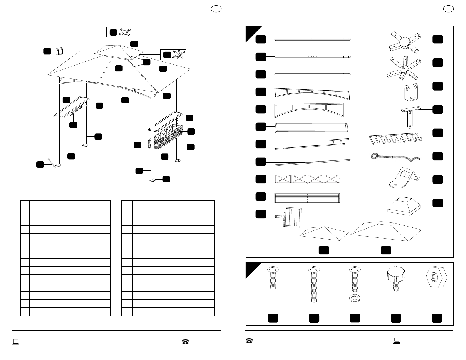
Compare todas las piezas incluidas en la caja con la lista de
piezas. Quite todos los materiales de protección y ponga
las piezas sobre una supercie no abrasiva para evitar que
se rayen. Si falta alguna pieza, NO intente ensamblar la
unidad. Llame a nuestro centro de atención al cliente (de
lunes a viernes de 9:00 a.m. a 5:00 p.m. EST) al
1-800-599-8898.
Precauciones
Lea todas las instrucciones antes de ensamblar la unidad.
¡No hacerlo puede resultar en un ensamblaje incorrecto,
lo que puede ocasionar lesiones! Ensamble la unidad
sobre una supercie blanda y no abrasiva, tal como
una alfombra o cartón, para evitar dañarla. Pida ayuda
para ensamblar las partes pesadas y voluminosas. Tras
la alineación nal, asegúrese de que todos los pernos y
tuercas estén rmemente apretados y estén cubiertos con
los embellecedores.
Limpieza y mantenimiento
Lavar el toldo con una solución de agua y jabón suave;
enjuagar bien. Secar completamente.
Para comenzar
ADVERTENCIA
MANTENER LAS LLAMAS Y LAS FUENTES DE CALOR ALEJADAS DEL
TEJIDO DE ESTE PRODUCTO/ARTÍCULO. Este producto/arculo está
fabricado con un tejido que cumple con la norma CPAI-84 de resistencia
a las llamas. No es ignífugo. El tejido arderá si entra en contacto connuo
con una llama. Aplicar cualquier sustancia extraña al tejido del producto/
arculo puede anular la resistencia a las llamas.
Aviso: En caso de malas condiciones meteorológicas o viento fuerte, quite el
Toldo principal (U) de la glorieta.
La glorieta está diseñada para dar sombra solamente. No use esta glorieta
en condiciones de viento y lluvia fuertes. El viento y la lluvia pueden
dañar la glorieta y podrían causarle lesiones a usted y a los demás. No es
impermeable y no se ha diseñado para utilizarse en la lluvia. El agua se
acumulará con facilidad en la tela del toldo y dañará la glorieta. No usar
o ensamblar en condiciones de lluvia, viento o tormenta.
Este producto está diseñado para el esparcimiento y no es un refugio contra
las condiciones meteorológicas adversas.
Advertencias y precauciones
1. Limpie la glorieta antes de guardarle; no la vuelva a embalar sino hasta que se
haya secado completamente.
2. Esta glorieta debe ser ensamblada por dos o más adultos.
3. El toldo de la glorieta debe quitarse en condiciones extremas o de viento
4. El límite de carga del gancho para utensilios es de 10 lb (4.5 kg).
5. El límite de peso para la cesta y los estantes es de 35 lb (15.8 kg).
6. Los componentes de acero para accesorios y muebles de jardín están tratados con
pintura antióxido. No obstante, debido a la naturaleza del acero, puede producirse
oxidación superficial (herrumbre) si el recubrimiento antióxido se raya; esto es un
proceso natural. Para minimizar las probabilidades de que esto ocurra, se
recomienda tener cuidado al ensamblar y manejar el producto, a fin de evitar
que la pintura se raye. Si se producen daños o rayas, se recomienda pintar el
área inmediatamente con pintura antióxido (no incluida). El óxido superficial
puede eliminarse fácilmente con una aplicación muy ligera de aceite normal de
cocina. Si se produce oxidación superficial y no se toma ninguna medida para
resolver el problema, el óxido puede comenzar a gotear sobre el balcón o patio, y
provocar manchas difíciles de eliminar.
SERVICIO POSVENTA

18 AFTER SALES SUPPORT
MODEL: 32720-20 PRODUCT CODE: 43472 05/2020
AFTER SALES SUPPORT 19
1800 599 8898 [email protected]
MODEL: 32720-20 PRODUCT CODE: 43472 05/2020
USA USA
Lista de piezas
Descripción Cant. Descripción Cant.
APoste 1 N Abrazadera de varilla 6
BPoste 1 O Abrazadera de estante 4
CPoste 2P Percha para utensilios 1
D Arco largo 2 Q Estaca 8
EArco corto 2 R Abrebotellas 1
F Estante 2S Base de poste 4
GVarillas de dos niveles del toldo 4T Toldo superior 1
HVarilla del toldo 2U Toldo principal 1
I Panel de la cesta 2AA Tornillo (M6X15 mm) 31
JEstante de la cesta 1 BB Tornillo (M6X32 mm) 10
KExtremo de la cesta 2 CC Perno y arandela (M6x18 mm) 12
L Conector del toldo superior 1 DD Tornillo con perilla 12
M Conector del toldo principal 1 EE Tuerca M6 6
L
NM
A
C
B
F
P
R
S
U
T
I
C
J
K
DE
H
G
O
Q
Lista de herrajes
A
B
U
I
G
F
E
D
C
B
A
T
L
AA BB CC EEDD
H
J
K
M
N
O
P
Q
R
S
SERVICIO POSVENTA SERVICIO POSVENTA

20 AFTER SALES SUPPORT
MODEL: 32720-20 PRODUCT CODE: 43472 05/2020
AFTER SALES SUPPORT 21
1800 599 8898 [email protected]
MODEL: 32720-20 PRODUCT CODE: 43472 05/2020
USA USA
Instrucciones de ensamblaje
PASO 1:
Deslice una cubierta de la pata (S) hacia abajo a lo largo de cada poste
(A, B y C) desde la parte superior hasta la parte inferior. La cubierta de
la pata (S) se ha concebido para cubrir la base circular de cada poste.
PASO 2:
Inserte 1 perno M6x32mm (BB) a través de cada abrazadera de varilla (N),
y atorníllelo en la parte superior del poste (A) y del poste (B). Ver la figura
1. Repita el mismo paso insertando 1 perno M6x32mm (BB) a través de la
abrazadera de varilla (N) y atorníllelo en la parte superior del poste (C).
PASO 3:
Inserte 1 perno M6x15mm (AA) a través de la abrazadera de varilla (N)
y atorníllelo en el centro superior del arco largo (D). Ver la figura 2. Siga
este mismo paso con el segundo arco largo (D).
Inserte dos pernos M6x15mm (AA) a través de un extremo del arco largo
(D) y dentro de la parte superior del poste (A). Repita este paso para fijar
el extremo opuesto del arco largo (D) al poste (C). Repita estos pasos
para ensamblar el poste (B) con el segundo arco largo (D) y el segundo
poste (C).
NAA
D
N
AA
C
S
A
BB
Fig. 1
Fig. 2
* No apriete completamente los tornillos durante esta parte del ensamblaje.
SERVICIO POSVENTA
Instrucciones de ensamblaje
PASO 4:
Inserte dos pernos M6x15mm (AA) a través de un extremo del arco
pequeño (E) y al interior de la rosca cerca de la parte superior del
poste (A). Inserte dos pernos M6x15mm (AA) a través de un extremo
del arco pequeño (E) y al interior de la rosca cerca de la parte superior
del poste (C). Conecte el poste (B) y el poste (C) entre sí insertando el
arco pequeño (E) con, usando dos pernos M6x15mm (AA) a ambos
lados. Una vez completado, ambos postes (C) deben estar situados
diagonalmente uno respecto del otro.
D
DE
E
A
C
C
B
AA
AA
(8) Tornillo
(M6X15 mm)
* No apriete completamente los tornillos durante esta parte del ensamblaje.
SERVICIO POSVENTA
AA
(10) Tornillo
(M6X15 mm)
BB
(4) Tornillo
(M6X32 mm)

22 AFTER SALES SUPPORT
MODEL: 32720-20 PRODUCT CODE: 43472 05/2020
AFTER SALES SUPPORT 23
1800 599 8898 [email protected]
MODEL: 32720-20 PRODUCT CODE: 43472 05/2020
USA USA
Instrucciones de ensamblaje
PASO 5:
Inserte dos pernos M6x15mm (AA) en el lado inferior del estante (F)
atravesando la abrazadera de estante (O) en un extremo; ver la figura
1. Repita este paso para acoplar una abrazadera de estante (O) al
extremo opuesto del estante (F). Repita estos pasos para ensamblar el
segundo estante (F) con las otras dos abrazaderas de estante (O).
PASO 6:
Inserte tres pernos M6x15mm (AA) en la parte inferior de un estante (F)
atravesando la percha para utensilios (P). Ver la orientación correcta
en la figura 2 para instalar esta pieza.
PASO 7:
Inserte dos tornillos con perilla (DD) en el estante (F) con la percha para
utensilios (P) atravesando ambas abrazaderas para utensilios (O) y en
los dos orificios con rosca superiores en todos los postes (A y C); ver la
figura 3. Repita este paso para acoplar el segundo estante ensamblado
(F) a los postes (B y C).
O
AA
F
F
DD
AA
P
Fig. 1
Fig. 2
Fig. 3
*Se aconseja usar la rosca superior de los postes (A, B y C) para los
estantes (F) de modo que queden nivelados; use un nivel en caso de
ser necesario. Los dos orificios inferiores se usarán posteriormente
en estas instrucciones para la cesta. No apriete completamente los
pernos durante esta parte del ensamblaje.
SERVICIO POSVENTA
Instrucciones de ensamblaje
PASO 8:
Inserte las varillas más largas de las varillas de dos niveles del toldo (G) en
los extremos más largos del conector del toldo principal (M) de forma que
queden fijadas en su sitio. Inserte las varillas cortas de las cuatro varillas
de dos niveles del toldo (G) en el conector del toldo superior (L) de forma
que queden fijadas en su sitio. Inserte las dos varillas del toldo (H) en los
extremos más cortos del conector del toldo principal (M) de forma que
queden fijadas en su sitio. Consultar la Figura 1 para la figura 1 para ver la
conexión correcta de estas piezas.
PASO 9:
Coloquelasvarillas ensambladasconlosconectoresencima dela estructura
ensamblada. Coloque los extremos de las varillas de dos niveles del toldo
(G) entre las abrazaderas de varilla (N) encima de cada poste (A, B y C).
Coloque los extremos de las varillas del toldo (H) entre las abrazaderas de
varilla (N) que se encuentran en el centro de ambos arcos largos (D). Inserte
seis pernos M6x32mm (BB) a través de todas las abrazaderas de varilla (N)
y a través de ambos tipos de varilla; ver la figura 2. Use una tuerca M6 (EE)
con M6x32mm (BB) para sujetar estas piezas entre sí.
* No apriete completamente los tornillos durante esta parte del ensamblaje.
SERVICIO POSVENTA
AA
(11) Tornillo
(M6X15 mm)
DD
(8) Tornillo con perilla
BB
(4) Tornillo
(M6X32 mm)
EE
(6) Tuerca M6
Fig. 1
L
M
G
G
G
H
BB
EE
Fig. 2

24 AFTER SALES SUPPORT
MODEL: 32720-20 PRODUCT CODE: 43472 05/2020
AFTER SALES SUPPORT 25
1800 599 8898 [email protected]
MODEL: 32720-20 PRODUCT CODE: 43472 05/2020
USA USA
Instrucciones de ensamblaje
PASO 10:
Inserte tres arandelas y pernos M6x18 (CC) en la rosca que se encuentra a
un lado del estante de la cesta (J) atravesando el panel de la cesta (I). Repita
este paso para ensamblar el segundo panel de la cesta (I) en el estante de
la cesta (J).
PASO 11:
Coloque los extremos de la cesta (K) entre los paneles de la cesta (I) en
ambos extremos del estante de la cesta (J). Consulte la orientación correcta
de esta pieza en la figura 1. Inserte dos pernos M6x18 (DD) en los extremos
de la cesta (K) atravesando los paneles de la cesta (I) a ambos lados para
terminar de ensamblar la cesta.
*Finalice el ensamblaje apretando firmemente todos los pernos que
hayan quedado flojos a lo largo del proceso de construcción.
Fig. 1
I
Step 10
Step 11
I
J
CC
K
CC
K
I
* No apriete completamente los tornillos durante esta parte del ensamblaje.
Paso 10
Paso 11
SERVICIO POSVENTA
Instrucciones de ensamblaje
PASO 12:
Inserte tornillos con perilla (DD) a través de las abrazaderas en los
extremos de la cesta (K) y en las roscas restantes en los postes (B y C); ver
la figura1 y la figura2. Apriete los tornillos con perilla (DD)completamente
para asegurar la cesta en su sitio.
PASO 13:
Inserte dos pernos M6x15mm (AA) en la rosca cerca del centro del poste
(A) atravesando el abrebotella (R); ver la figura 3.
PASO 14:
Coloque el toldo superior (T) sobre las varillas superiores de las varillas
de dos niveles del toldo (G) de forma que los extremos de las varillas
encajen en los bolsillos debajo del toldo.
Coloque el toldo principal (U) sobre la varilla inferior de las varillas de
dos niveles del toldo (G) y las varillas del toldo (H). Despliegue el toldo
principal (P) completamente de forma que los extremos de las varillas
encajen en los bolsillos de la parte inferior.
PASO 15:
Levante las bases de los postes (S) e introduzca dos estacas (Q) a través
de los orificios designados en la parte inferior de cada poste (A, B y C) y
clávelos en la tierra para mayor estabilidad; ver la figura 4.
SERVICIO POSVENTA
CC
(12) Perno y arandela
(M6x18 mm)
T
U
DD
Q
R
AA
Fig. 4
Fig. 3
Fig. 1
Fig. 2
AA
(2) Tornillo
(M6X15 mm)
DD
(4) Tornillo con perilla

Sus datos:
Fecha de la compra*
Nombre
Dirección
Correo electrónico
Lugar de la compra
Descripción de la avería:
Devuelva su tarjeta de garana
completada junto con el producto
defectuoso a:
TDC USA, Inc.
5 Industrial Roads
Fairfield, NJ 07004
United States of America
* Le recomendamos que guarde el recibo con esta tarjeta de garana.
AÑO DE GARANTÍA
1
1800 599 8898
SERVICIO POSVENTA
USA
MODELO:
32720-20 05/2020
43472
Las líneas telefónicas
están disponibles de
lunes a viernes, de
9 a.m. a 5 p.m. EST
TARJETA DE GARANTÍA
GLORIETA PARA PARRILLA
Fecha de compra
Lugar de la compra
*Recomendamos que guarde el recibo con esta tarjeta de garana. Debe incluir una copia de su recibo.
Las líneas telefónicas
están disponibles de
lunes a viernes, de
9 a.m. a 5 p.m. EST
CONDICIONES DE LA GARANTÍA COMPLETA
DE ALDI INC.
Esmado cliente:
La garana ALDI es una garana completa que le ofrece los siguientes benecios:
Período de garana: 1 año a parr de la fecha de la compra.
Costos: Reparación/sustución gras o reembolso.
No hay costos de transporte.
AVISO Póngase en contacto con nuestra línea directa de atención
por teléfono, correo electrónico o fax antes de retornar el
producto. Esto nos permite proporcionar ayuda en caso de
posibles errores del operador.
Para hacer una reclamación bajo la garana, por favor envíenos:
El arculo defectuoso junto con todas las piezas, el recibo de compra
original y la tarjeta de garana completada de manera apropiada.
La garana no cubre a los daños ocasionados por:
Accidentes o eventos imprevistos en la estructura [partes metálicas]
(por ejemplo, viento, nieve, rayos, fuego).
Deterioro, decoloración, hundimiento o eventos imprevistos en los
toldos (por ejemplo, viento, sol, lluvia, mascotas/animales).
Uso o transporte inadecuados.
Incumplimiento de las instrucciones de seguridad y mantenimiento.
Otro tratamiento o modicación inadecuados.
Después del vencimiento del período de garana, ene la posibilidad de mandar a
reparar su producto si usted corre con los gastos. Se le nocará por adelantado el
costo de reparación.
Esta garana le otorga derechos legales especícos y es posible que también tenga
otros derechos que pueden variar de un estado a otro, pero no ene como n
exceder los requisitos legales mínimos que aquí se incluyen.
Esta garana no limita la obligación legal del vendedor derivada de cualquier
garana implícita. El período de garana solo se puede extender hasta donde lo
permita la ley.

YEAR WARRANTY
1
AFTER SALES SUPPORT
SERVICIO POSVENTA
1800 599 8898
MODEL:
32720-20 05/2020
43472
DIST. & SOLD EXCLUSIVELY BY:
ALDI
BATAVIA, IL 60510
This manual suits for next models
1
Table of contents
Languages:
Other Gardenline Outdoor Furnishing manuals

Gardenline
Gardenline 22095-18 User manual

Gardenline
Gardenline 22098-18 User manual

Gardenline
Gardenline 4699 User manual

Gardenline
Gardenline 7884 User manual

Gardenline
Gardenline 1537 User manual

Gardenline
Gardenline 22466 User manual

Gardenline
Gardenline 7884 User manual

Gardenline
Gardenline 7884 User manual

Gardenline
Gardenline 22096-18 User manual

Gardenline
Gardenline 32720 User manual