Garner PD-4 User manual

4075-270 Rev H
Model PD-4
(Physical Hard Drive Destroyer)
Operation Manual
10620 Industrial Ave. Suite 100
Roseville CA 95678
USA
(916) 784-0200
(800) 624-1903

Table of Contents
Introduction.............................................................................................................................................................. 1
Important Instructions.............................................................................................................................................. 1
PD-4 Component Identification............................................................................................................................... 2
Front Panel Identification................................................................................................................................. 2
Front Panel Description .................................................................................................................................... 2
Inside Component Identification ...................................................................................................................... 3
Inside Component Description ......................................................................................................................... 3
Operating the PD-4 ................................................................................................................................................. 4
Initial Startup............................................................................................................................................................ 4
Sequence of Auto Mode Operation ................................................................................................................... 4
Sequence of Manual Mode Operation .............................................................................................................. 5
Cleaning the Debris Tray.................................................................................................................................. 5
Instruction for Use ................................................................................................................................................... 6
Operating Environment: ................................................................................................................................... 6
Cleaning:............................................................................................................................................................. 6
Parts List.................................................................................................................................................................. 7
Specifications .......................................................................................................................................................... 8
Declaration of Conformity ....................................................................................................................................... 9
Limited Warrany .................................................................................................................................................... 10

Page 1
Introduction
Thank you for purchasing the PD-4 Physical Hard Drive Destroyer. The PD-4 will physically destroy working
and non-working hard disk drives (HDD), Network HDD, Half-Height HDD, Standard HDD and Laptop HDD by
deforming the data platters, pc board and frame of the hard drive.
To ensure a safe operation of the PD-4, please be sure to read and understand the contents of this operation
manual before operating the PD-4. We also advise you to keep this manual at hand for a quick reference in
the future.
Important Instructions
PLEASE READ THIS INFORMATION
BEFORE USING MODEL PD-4
This shipment was packaged and delivered to the carrier with utmost care to ensure safe delivery of goods to
you, our valued customer. PLEASE RETAIN ALL SHIPPING MATERIALS FOR FUTURE USE. FAILURE
TO DO SO MAY RESULT IN FREIGHT DAMAGE AND VOID WARRANTY.
In the event that you must transport model PD-4 to a different location or to the factory for repair service, you
must package it for safe delivery. Failure to do so may result in freight damage and will void the factory
warranty.
Please contact Garner Products, Inc. at (800) 624-1903 for further information if required.

Page 2
PD-4 Component Identification
Front Panel Identification
Front Panel Description
1) Power Switch
Applies power to the PD-4.
2) Destroy Button
Initiates the destruction function. Note: When pressed initially with the wedge in
the home position and in Auto Mode, the PD-4 will first Auto-size requiring a
second push of the “Destroy” button.
3) Size Button
Toggles between Auto-Mode and Manual Mode when held down for three
seconds or when Green, Yellow and Blue lights flash in a chasing sequence. In
Auto Mode, initiates the Auto-Size function. In Manual Mode each button
press moves the destruction wedge down one of four sections.
4) Blue Lamp
Illuminates when the wedge is moving down during Destruction function.
5) Yellow Lamp
Auto Mode:
Solid – Indicates Auto-Size function is running.
Flashing – Door is open and no media detected.
Manual Mode:
Solid – Indicates destruction wedge is moving to new position.
6) Green Lamp
Auto Mode:
Solid - Indicates ready, the door is closed, media is detected.
Flashing – Indicates the door is open and media is detected.
Manual Mode:
Solid - Indicates ready, the door is closed.
Flashing – Indicates the door is open.
7) Front Door
Prevents access to the HDD and Destruction wedge during the destruction
process. If opened during the destruction process the destruction wedge will
automatically stop.

Page 3
Inside Component Identification
Inside Component Description
1) Door / Door Handle
Prevents access to the hard drives and Destruction Wedge during the
destruction process. If opened during the destruction process the
destruction wedge will automatically stop. When the door is closed, the
destruction wedge will retract..
2) Destruction Wedge
The Destruction Wedge pushes down on the hard drive(s) bending and
breaking the external and internal components, rendering the hard drive
inoperable.
3) Hard Drives
Image shows the proper location of two 1” hard drives stacked on top of each
other. Note: Hard drives are centered between the two Support Rails.
4) Support Rails
Supports and aligns the hard drive(s).
5) Debris Tray
Removable tray helps collect hard drive debris caused by the destruction
process. The Debris Tray can be easily lifted out and emptied.

Page 4
Operating the PD-4
Initial Startup
1) Unpack the shipping carton/case and take out the PD-4 Physical Destroyer.
2) Please make sure that the PD-4 has not been damaged during transportation.
3) Please retain all shipping materials for possible future use.
4) Confirm power requirements as indicated on label located on back of PD-4.
Sequence of Auto Mode Operation
1) Press the “Power Switch” to “ON”. The Blue and Green lamps illuminate briefly, the Yellow lamp flashes
and the destruction wedge returns to home position.
2) Open door and place the hard drive(s) on the Support Rails.
Note: Center the hard drive between right and left Support Rails and ensure the hard drive(s) are
pushed to the back (Laptop drives can be oriented perpendicular to the standard drive orientation to
mount on both support rails). The Green light will illuminate when the hard drive(s) are detected by
the auto-sizing sensors located on the back wall of the destruction chamber.
3) Close the door and press the “Size” button.
Notes:
a. The PD-4 will automatically size the hard drive(s) and lower the wedge to just above the
hard drive and stop. This will happen only on the first hard drive or until the “Size” button is
pressed again or the PD-4 is powered off.
b. Pressing the “Size” button at anytime during auto mode operation will return the destruction
wedge to the home position
4) Press the “Destroy” button. The PD-4 will destroy the media in the destruction chamber in a pre-set
cycle and return to the previously set position to be ready to destroy the next piece of media of the
same size.
5) Open the door and remove the hard drive(s) when the Green light illuminates, indicating the destruction
process is complete.
6) Insert media and close the door and repeat from Step 4 until the job is complete or repeat from Step 3 if
a different height media is inserted in the chamber.

Page 5
Sequence of Manual Mode Operation
1) Press the “Power Switch” to “ON”.
2) Press and hold the “Size” button for three seconds or until the Green, Yellow and Blue lights illuminate
in a chasing sequence.
3) Open the door and place the Hard Drive(s) on the Support Rails.
4) Press the “Size” button once to lower the Destruction Wedge to level four, the uppermost level. Press
the “Size” button again to lower the Destruction Wedge to the next lower level and so on until the unit is
sized to the desired level for the destruction of the media in the chamber.
Notes:
a. The destruction wedge should be located just above the media before the “Destroy” button is
pushed. Open the door and remove the hard drive(s) when the Green lamp illuminates, indicating
the destruction process is complete.
b. The Yellow light will blink four times for level four, three times for level three and so on. A total
of four levels are available. After the Destruction Wedge reaches level one, the lowest level, the
next push of the “Size” button will return the Destruction Wedge to the Home position.
5) Press the “Destroy” button.
Cleaning the Debris Tray
Open the door and remove the Hard Drive(s) after the destruction wedge returns to the top position and the
motor stops.
As a safety precaution, do not open the door until the destruction wedge has returned to the top
position and the motor has stopped.
After the PD-4 destroys the Hard Drives, small fragments of the hard drive may be left on the Support
Rails and will be left in the Debris Tray. Sweep or vacuuming the fragments from the Support Rails
into Debris Tray located on the bottom of the Destruction Chamber in between the Support Rails of the
PD-4. When enough debris has accumulated, remove the Debris Tray and empty it. Place the
Debris Tray back in and resume the destruction process.
Note: Make sure that the Debris Tray is inserted all the way to the back of the chamber or the door will
not shut completely.

Page 6
Instruction for Use
When using PD-4, please pay special attention to the following. Failure to follow these procedures could cause
serious failure or malfunction.
Operating Environment:
Please do not use
or keep the PD-4 in environments with excessive heat, cold, humidity, or dust.
Use caution when bringing the PD-4 from a cold environment into a warm environment. If moisture has
accumulated due to a sudden change of temperature, wait (1) hour before operating the PD-4.
Do not use the PD-4 on uneven or unstable surfaces. Only use the PD-4 on a secure horizontal surface.
Cleaning:
Please wipe dirt off with a soft and dry cloth. Do not use chemicals or solvents.
When cleaning the unit, make sure that the power is not connected, and wipe with a soft and dry cloth.
To achieve proper hard drive placement, sweep or vacuum Hard Drive debris from the inside of the PD-4.
Empty debris from the Debris Tray and remove any debris that has remained on the Support Rails. Excess
debris will alter the placement of the HDD and may cause damage to the PD-4.

Page 7
Parts List
Part Number
Description
2500-091B
Rail, door slide
2600-013
Fan, 24vdc
2600-014 Filter assy
2600-015
Finger guard, fan
2825-278
Bolt, shoulder 3/8 dia .75
2825-289
Knob, plastic
2825-294A
Tray, debris
335-0010
Fuseholder, 3AG
356-0001
SS Relay, 240VAC 40A
3500-059B
Gear, 48 tooth
3500-060E Gear, 16 tooth
3500-064E
Shaft, gear
3500-066D
Gear, spur 60 tooth
3500-068
Motor, 110/115
4000-007 Power Supply, 90-264VAC
4300-026
Fuse, 10A 250V slow blow
4075-270H
Manual, operation PD-4
4500-023
Relay, SS SPST 5A
4700-045
Resistor, R5 50W
5100-001
Pushbutton switch
5100-034
Switch, power rocker
SA1400-216B
Rail, crush chamber
MS2400-058C
Rail, media support
SA2500-059B
Plate, compression
MS2400-059B
Screw, acme
MS5400-006B
Wedge, media destroyer
SA1400-215C Plate, crush chamber side
SA1400-258B
Door, crush chamber
SA1700-205D
PCB, main control populated
SA1700-206B
PCB, control panel populated
SA1700-207G
PCB, chamber sense
SA2400-060B
Bar, media stop
SA2400-062C
Rail, bumper
SA2500-090B
Bracket, index cntr
SA3500-070C
Index card, motor
SA6000-085A
Harness, wiring PD-4

Page 8
Specifications
Power Supply
Standard: 120V ±5% 60 Hz
Optional: (100V, 110-115V, 200V, 220-240V) (50 or 60 Hz)
Please check the power configuration label located on the back
of the PD-4.
Power Consumption
10A @ 120VAC
Cycle Time PD-4 Standard Model
Full Cycle: 20 seconds
Destroy Cycle: 10 seconds
PD-4 Standard Model Capacity
2.5" and 3.5" hard Drives.
Disk drives up to 1.66" high.
Two 1” high standard hard disk drives.
Up to six laptop hard disk drives.
Operating Environment
41°F - 104°F (5°C - 40°C), Humidity: 10 to 80% (Non
Condensing)
Physical Weight
PD-4: Net 82 lbs. (37.25Kg)
Case: 23 lbs. (10.45 Kg)
Shipping Weight
125 lbs (56.8 Kg)
Physical Dimensions
PD-4: 15.75 in. (L) x 7.1in. (W) x 14.1 in. (H)
Case: 21 in. (L) x 25 in. (W) x12 in. (H)
Shipping Dimensions
34 in. (L) x 26 in. (W) x 18 in. (H)
Warranty
1 Year Parts and Labor Limited Warranty
Duty Cycle
Continuous*
* Ambient temperatures above 75 degrees F will have an effect on duty cycle.
10620 Industrial Ave. Suite 100
Roseville CA 95678
(916) 784-0200
(800) 624-1903
www.garner-products.com
Page 9
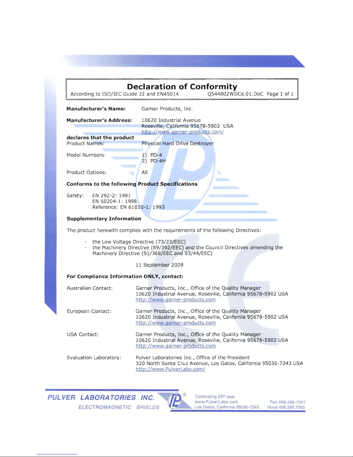
Declaration of Conformity

Page 10
GARNER PRODUCTS, INC. LIMITED WARRANTY
AND
WARRANTY RETURN POLICY
Garner Products, Inc. (“Garner”) warrants this Garner-branded product against defects in materials and workmanship under
normal use for a period of ONE (1) YEAR from the date of purchase by the original end-user as evidenced by original end-user’s
packing slip or invoice (“Warranty Period”). If a defect arises and a valid claim is received within the Warranty Period, at its
option, Garner will either: (1) repair the product, (2) exchange the product, or (3) request that end-user replace defective parts
with new or refurbished user-installable parts that Garner provides in fulfillment of its warranty obligations. A replacement
product or part, including a user-installable part that has been installed in accordance with instructions provided by Garner,
assumes the remaining warranty of the original product or ninety (90) days from the date of replacement or repair, whichever
provides longer coverage. Garner’s obligation is limited to the cost of material and labor to repair or replace and does not
include transportation expenses.
LIMITATIONS
This warranty does not apply: (a) to cosmetic damage, including but not limited to scratches, dents and broken plastic; (b) to
normal wear; (c) to damage caused by accident, abuse, neglect, misuse, flood, fire, earthquake or other external causes; (d) to
damage caused by operating the product outside the permitted or intended uses described by Garner; (e) to damage caused by
service performed by anyone who is not a representative of Garner or a Garner authorized service provider; (f) to a product or
part that has been modified to alter functionality or capability without the written permission of Garner; or (g) if any Garner serial
number has been removed or defaced.
DISCLAIMER
TO THE EXTENT PERMITTED BY LAW, THIS WARRANTY AND REMEDIES SET FORTH ABOVE ARE EXCLUSIVE AND IN
LIEU OF ALL OTHER WARRANTIES, REMEDIES AND CONDITIONS, WHETHER ORAL OR WRITTEN, STATUTORY,
EXPRESS OR IMPLIED. AS PERMITTED BY APPLICABLE LAW, GARNER SPECIFICALLY DISCLAIMS ANY AND ALL
STATUTORY OR IMPLIED WARRANTIES, INCLUDING, WITHOUT LIMITATION, WARRANTIES OF MERCHANTABILITY,
FITNESS FOR A PARTICULAR PURPOSE AND WARRANTIES AGAINST HIDDEN OR LATENT DEFECTS, IF GARNER
CANNOT LAWFULLY DISCLAIM STATUTORY OR IMPLIED WARRANTIES, THEN TO THE EXTENT PERMITTED BY LAW.
ALL SUCH WARRANTIES SHALL BE LIMITED IN DURATION TO THE DURATION OF THIS EXPRESS WARRANTY AND TO
REPAIR OR REPLACEMENT SERVICE AS DETERMINED BY GARNER IN ITS SOLE DISCRETION. No Garner dealer,
reseller, agent, or employee is authorized to make any modification, extension, or addition to this warranty. If any term is held to
be illegal or unenforceable, the legality or enforceability of the remaining terms shall not be affected or impaired.
EXCEPT AS PROVIDED IN THIS WARRANTY AND TO THE EXTENT PERMITTED BY LAW, GARNER IS NOT
RESPONSIBLE FOR DIRECT, SPECIAL, INCIDENTAL OR CONSEQUENTIAL DAMAGES RESULTING FROM ANY BREACH
OF WARRANTY OR CONDITION, OR UNDER ANY OTHER LEGAL THEORY, INCLUDING BUT NOT LIMITED TO LOSS OF
USE; LOSS OF REVENUE; LOSS OF ACTUAL OR ANTICIPATED PROFITS (INCLUDING LOSS OF PROFITS ON
CONTRACTS); LOSS OF USE OF MONEY; LOSS OF BUSINESS; LOSS OF OPPORTUNITY; LOSS OF GOODWILL; LOSS
OF REPUTATION; LOSS OF DAMAGE TO OR CORRUPTION OF DATA; OR ANY INDIRECT OR CONSEQUENTIAL LOSS
OR DAMAGE HOWSOEVER CAUSED INCLUDING THE REPLACEMENT OF EQUIPMENT AND PROPERTY, ANY COSTS
OF RECOVERING, PROGRAMMING, OR REPRODUCING ANY PROGRAM OR DATA STORED OR USED AND ANY
FAILURE TO MAINTAIN THE CONFIDENTIALITY OF DATA. IN NO EVENT SHALL GARNER BE LIABLE FOR ANY CLAIMS,
WHETHER ARISING FROM BREACH OF CONTRACT OR WARRANTY OR CLAIMS OF NEGLIGENCE OR NEGLIGENT
MANUFACTURE, IN EXCESS OF THE PURCHASE PRICE.
WARRANTY RETURN POLICY
If a problem occurs with this product, contact Garner directly by Email info@garner-products.com by phone at (916) 784-
0200 to obtain technical support and/or to get a Return Authorization Number (RA#). All returns must be specifically authorized
by Garner prior to shipment and returned to Garner FREIGHT PREPAID with the RA# marked prominently near the shipping
label. Securely package the product. It is end-user’s responsibility to ensure the product is packaged properly to prevent
damage during transit to Garner.Garner will provide product packaging to end-user at end-user’s request and expense.
Enclose proper documentation, including RA#, the return address, a name and phone number of the contact person, the serial
number of the merchandise being returned and a description of the reason for the return. Omission of any of this information
may delay service. Garner recommends end-user insure the shipment; otherwise end-user accepts the risk if product is lost or
damaged in shipment.
Garner will pay to ship the repaired or replacement products to end-user’s shipping dock if end-user’s delivery address is in the
United States (excluding Puerto Rico and U.S. possessions and territories); otherwise Garner will ship the product to end-user
freight collect. Garner will select method for return shipment. Alternate shipment methods may be made at end-user’s expense.
Table of contents
Popular Office Equipment manuals by other brands


3-form
3-form SimpleSpec 600.01 installation manual

hushoffice
hushoffice hushtwin HUS-BX-019 Maintenance and safety manual

Siemens
Siemens HIPATH 2000 user guide

OCEE DESIGN
OCEE DESIGN SASS-0100 quick start guide

Canon
Canon Inner Finisher-A1 Service manual

Unify
Unify OpenScape DECT Phone S5 Base user guide