Canon Inner Finisher-A1 User manual

654321
Inner Finisher-A1
Inner Finisher Additional Tray-A1
Service Manual

0
0
b
b
Application
This manual has been issued by Canon Inc. for qualied persons to learn technical theory,
installation, maintenance, and repair of products. This manual covers all localities where the
products are sold. For this reason, there may be information in this manual that does not
apply to your locality.
Corrections
This manual may contain technical inaccuracies or typographical errors due to improvements
or changes in products. When changes occur in applicable products or in the contents of this
manual, Canon will release technical information as the need arises. In the event of major
changes in the contents of this manual over a long or short period, Canon will issue a new
edition of this manual.
The following paragraph does not apply to any countries where such provisions are
inconsistent with local law.
Trademarks
The product names and company names used in this manual are the registered trademarks
of the individual companies.
Copyright
This manual is copyrighted with all rights reserved. Under the copyright laws, this manual may
not be copied, reproduced or translated into another language, in whole or in part, without the
written consent of Canon Inc.
(C) CANON INC. 2009
Caution
Use of this manual should be strictly supervised to avoid disclosure of condential
information.

0
0
c
c
Explanation of Symbols
The following symbols are used throughout this Service Manual.
Symbols Explanation Symbols Explanation
Check. Remove the claw.
Check visually. Insert the claw.
Check the noise. Use the bundled part.
Disconnect the connector. Push the part.
Connect the connector. Plug the power cable.
Remove the cable/wire
from the cable guide or wire
saddle.
Turn on the power.
Set the cable/wire to the
cable guide or wire saddle.
Remove the screw.
Tighten the screw.
The following rules apply throughout this Service Manual:
1. Each chapter contains sections explaining the purpose of specic functions and the
relationship between electrical and mechanical systems with reference to the timing of
operation.
In the diagrams, represents the path of mechanical drive; where a signal name
accompanies the symbol, the arrow indicates the direction of the electric
signal.
The expression "turn on the power" means ipping on the power switch, closing the
front door, and closing the delivery unit door, which results in supplying the machine with
power.
2. In the digital circuits, '1' is used to indicate that the voltage level of a given signal is
"High", while '0' is used to indicate "Low". (The voltage value, however, differs from
circuit to circuit.) In addition, the asterisk (*) as in "DRMD*" indicates that the DRMD
signal goes on when '0'.
In practically all cases, the internal mechanisms of a microprocessor cannot be checked
in the eld. Therefore, the operations of the microprocessors used in the machines
are not discussed: they are explained in terms of from sensors to the input of the DC
controller PCB and from the output of the DC controller PCB to the loads.
The descriptions in this Service Manual are subject to change without notice for product
improvement or other purposes, and major changes will be communicated in the form of
Service Information bulletins.
All service persons are expected to have a good understanding of the contents of this Service
Manual and all relevant Service Information bulletins and be able to identify and isolate faults
in the machine.

0
0
d
d

0
0
e
e
Contents
0Safety Precautions
Notes Before it Works Serving---------------------------------------------0-2
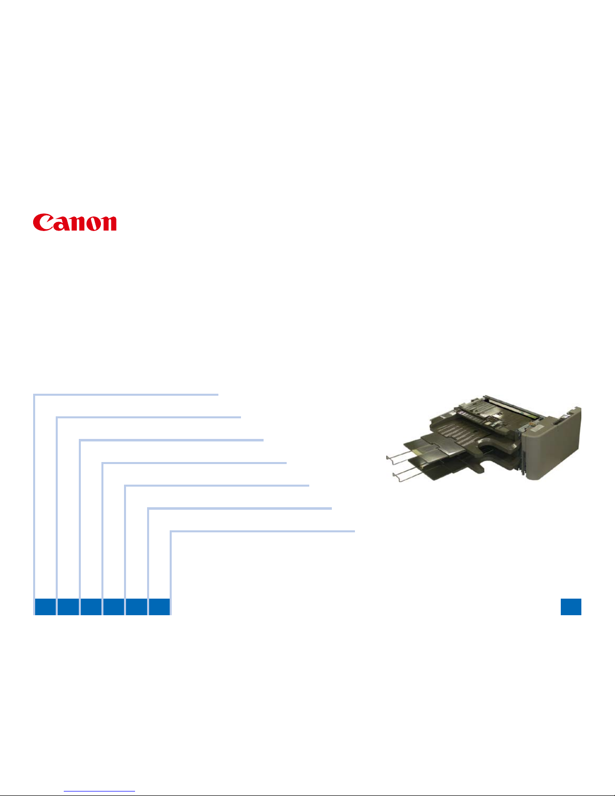
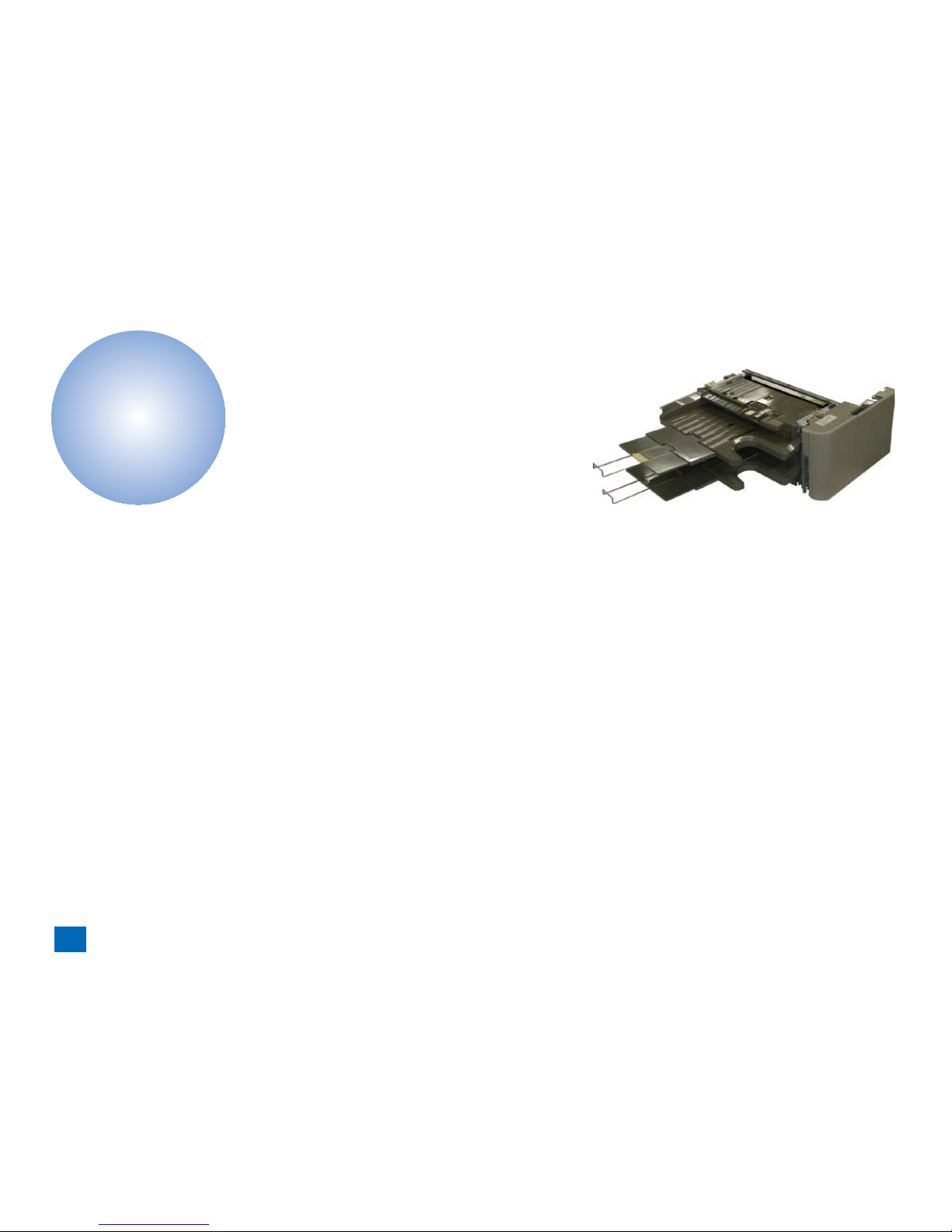
1Produt Outline
Features -------------------------------------------------------------------------1-2
Specications ------------------------------------------------------------------1-3
Names of Parts ----------------------------------------------------------------1-4
External View 1--------------------------------------------------------------------- 1-4
External View 2--------------------------------------------------------------------- 1-4
External View 3--------------------------------------------------------------------- 1-5
Cross Section ----------------------------------------------------------------------- 1-5
2Technology
Basic Conguration-----------------------------------------------------------2-2
Outline of basic operation-------------------------------------------------------- 2-2
Non-sort operation-------------------------------------------------------------------------- 2-2
Offset operation ----------------------------------------------------------------------------- 2-2
Stapling operation -------------------------------------------------------------------------- 2-3
Servicing Work-----------------------------------------------------------------2-5
Scheduled Servicing -------------------------------------------------------------- 2-5
Customer maintenance----------------------------------------------------------- 2-5
Cleaning the offset roller------------------------------------------------------------------ 2-5
Version Upgrade ------------------------------------------------------------------- 2-5
3Periodic Servicing
Periodic Service Works------------------------------------------------------3-2
4Parts Replacement and Cleaning Procedure
List of Parts ---------------------------------------------------------------------4-2
Motors/Switches/Solenoids------------------------------------------------------ 4-2
Sensors1 ----------------------------------------------------------------------------- 4-2
Sensors2 ----------------------------------------------------------------------------- 4-3
PCBs ---------------------------------------------------------------------------------- 4-3
Main Units-----------------------------------------------------------------------4-4
Removing the Upper Unit-------------------------------------------------------- 4-4
Removing the Gripper Unit ------------------------------------------------------ 4-7
Consumable Parts Requiring Periodic Replacement and Cleaning
Points ----------------------------------------------------------------------------4-8
Removing the Stapler Unit------------------------------------------------------- 4-8
Removing the Offset Roller------------------------------------------------------ 4-9
Removing the Shutter Unit -----------------------------------------------------4-10
Removing the Paper retainer (front/rear) ----------------------------------- 4-11
Removing the Solenoid---------------------------------------------------- 4-13
Removing the Paper Lever Drive Solenoid---------------------------------4-13
Removing the Staple Solenoid ------------------------------------------------4-15
Removing the Motors ------------------------------------------------------ 4-18
Removing the Shift Roller Release Motor ----------------------------------4-18
Removing the Shift Motor-------------------------------------------------------4-19
Removing the Feed Motor ------------------------------------------------------4-21
Removing the Gripper Open/Close Motor ----------------------------------4-22
Removing the STP Move Motor/Gripper Unit Move Motor -------------4-22
Removing the Entrance Roller Release /Stopper HP Motor -----------4-25
Removing the Additional Tray Lift Motor ------------------------------------4-26
Removing the Tray Lift Motor --------------------------------------------------4-27
Removing the Switches --------------------------------------------------- 4-30
Removing the Front Cover Switch--------------------------------------------4-30
Removing the Staple Safety Switch------------------------------------------4-31
Removing the PCB --------------------------------------------------------- 4-34
Removing the Additional Tray PCB-------------------------------------------4-34
Removing the Finisher Controller PCB--------------------------------------4-35
Removing the Flexible Cable Broadcast PCB-----------------------------4-37
Others-------------------------------------------------------------------------- 4-38
Stapler Cradle Installation Procedure----------------------------------------4-38
5Installation(Inner Finisher-A1)
Making Pre-installation Checks--------------------------------------------5-2

0
0
f
f
Cautions at the Installation ------------------------------------------------------ 5-2
Kontrollen vor der Installation (German/Deutsch) --------------------5-2
Vorsichtshinweise zur Installation---------------------------------------------- 5-2
Checking Bundled Components-------------------------------------------5-3
How to Utilize This Installation Procedure ------------------------------5-4
When Using the Contained Parts (Bundled Components
in the Shipping Carton) ----------------------------------------------------------- 5-4
Symbols in the Illustration ------------------------------------------------------- 5-4
Installation Procedure--------------------------------------------------------5-5
Installation Procedure------------------------------------------------------------- 5-5
6Installation(Addtional Tray-A1)
Making Pre-installation Checks--------------------------------------------6-2
Cautions at the Time of Installation-------------------------------------------- 6-2
Checking Bundled Components-------------------------------------------6-3
How to Utilize This Installation Procedure ------------------------------6-4
When Using the Contained Parts(Bundled Components in the Shipping
Carton)-------------------------------------------------------------------------------- 6-4
Symbols in the Illustration ------------------------------------------------------- 6-4
Installation Procedure--------------------------------------------------------6-5
Preparation to install in the host machine ----------------------------------- 6-5
Connecting to Connected Equipment----------------------------------------- 6-6
7Appendix
Service Tools -------------------------------------------------------------------7-2
Solvents and Oils ------------------------------------------------------------------ 7-2
Special Tools ------------------------------------------------------------------------ 7-2
General Circuit Diagram-----------------------------------------------------7-3

Safety Precautions
Notes Before it Works Serving
■

0
0
0-2
0-2
Safety Precautions > Notes Before it Works Serving
Notes Before it Works Serving
Caution:
At servicing, be sure to turn off the power source according to the specied steps and
disconnect the power plug.
Caution:
Do not turn off the power switch when downloading is under way.
Turning off the main power switch while downloading is under way can disable the
machine.

1
1Produt Outline
Produt Outline
Names of Parts
Specications
Names of Parts
■
■
■

1
1
1-2
1-2
Produt Outline > Features
Features
A variety of nishing functions
2 delivery tray + Multi stapling
Large tray capacity (500 sheets+)
Utilize the inner room of the system
•
•

1
1
1-3
1-3
Produt Outline > Specications
Specications
Item Specications
Stacking method Stacking tray descending method
Paper ejection Face-down ejection
Stacking alignment Center alignment
Stackable paper
size
Feeding direction 139.7mm - 457mm
Cross-feeding direction 100.0mm - 320mm
Paper weight 52-256g/m2 (Japanese post card supported))
Number of tray 1 (+additional option tray)
Finishing modes Non-sort stacking A3/A4/A4R/A5/A5R/B4/B5/B5R/Japanese Post
Card/EXE/LDR/LGL/LTR/LTR-R/STMT/STMT-R
8K/16K/16K-R
SRA3(320X450)/A3+(305X457)
Bunch offset stacking A3/A4/A4R/B4/B5
LDR/LGL/LTR/LTR-R
8K/16K
Staple stacking A3/A4/A4R/B4/B5
LDR/LGL/LTR/LTR-R
8K/16K
Stacking capacity Processing tray S size: 50 sheets or Less
Length in feeding direction: 139.7mm-215.9mm
L size: 30 sheets or Less
Length in feeding direction: more than 215.9mm-
457.0mm
Standard tray (lower
tray) only
S size: 62.5mm high or less (62.5mm is equivalent
to 500 sheets+/-.)
L size: 62.5mm high or less (62.5mm is equivalent to
500 sheets+/-.)
When the
Additional
Tray-A1 is
installed
Additional
Tray-A1
(Upper tray))
S size: 12.5mm high or less (12.5mm is equivalent
to 100 sheets+/-.)
L size: 12.5mm high or less (12.5mm is equivalent to
100 sheets+/-.)
Standard
tray
(lower tray)/
Random
stacking
S size: 25.0mm high or less (25.0mm is equivalent
to 200 sheets+/-.)
L size: 25.0mm high or less (25.0mm is equivalent to
200 sheets+/-.)
Standard
tray
(lower tray)/
Cascade
stacking
S size: 62.5mm high or less (62.5mm is equivalent
to 500 sheets+/-.)
L size: 62.5mm high or less (62.5mm is equivalent to
500 sheets+/-.)
Stapled stack Above-mentioned heights or within 30 books
Item Specications
Capable size for
alignment
Non-sort stacking Width: 100mm-320mm
Bunch offset stacking Width: 210mm-297mm
Staple stacking Width: 210mm-297mm
Paper detection Processing tray Available
Standard tray/Additional
Tray-A1
Available
Capable size for
stapling
Single corner stapling
(front or rear
A3/B4/A4/A4R/B5
LDR/LGL/LTR/LTR-R
8K/16K
Double stapling
(sidestitching)
A3/B4/A4/A4R/B5
LDR/LGL/LTR/LTR-R
8K/16K
Number of paper
stapled
Small size
(A4/B5/LTR/16K)
Plain paper (52-81.4g/m2) : 50 sheets (Max: 2
sheets x Cover paper (256g/m2) + 48 sheets x
bookblock (81.4g/m2))
Plain paper (more than 81.4g/m2-105.0g/m2): 30
sheets
Thick paper (more than 105.0g/m2 - 256g/m2: 2
sheets
Large size
(A3/B4/A4R/LDR/LGL/
LTR-R/8K)
Plain paper(52-81.4g/ 30m2) : 30 sheets
Plain paper (more than 81.4g/m2-105.0g/m2): 20
sheets
Thick paper (more than 105.0g/m2 - 256g/m2: 2
sheets
Staple replenishment Exclusive staple cartridge (5000 staples)
Staple Exclusive staple
Staple run-out detection Available
Manual stapling Unavailable
Control panel Not exsisting
Power supply Supplied by the host machine
Dimensions 424.2mm×552.1mm×228.5mm(W×D×H)
Mass Approx. 9.8Kg
T-1-1T-1-1

1
1
1-4
1-4
Produt Outline > Names of Parts > External View 2
Names of Parts
External View 1
Tray paper holdig arm
Upper guide part
Stack tray
Switchback guide
F-1-1F-1-1
External View 2
Stapler
Additional Tray-A1
Stack extension tray 2
Stack extension tray 1
F-1-2F-1-2

1
1
1-5
1-5
Produt Outline > Names of Parts > Cross Section
External View 3
Finisher front cover
F-1-3F-1-3
Cross Section
[1]
[6]
[5]
[4]
[3]
[2]
[9] [8] [7]
[1] Stack tray [6] Stapler
[2] Processing tray [7] Stapler
[3] Shift roller [8] Gripper
[4] Switchback part [9] Stack height detection lever
[5] Entrance roller
F-1-4F-1-4

2
2Technology
Technology
Basic Conguration
Work of Service
■
■

2
2
2-2
2-2
Technology > Basic Conguration > Outline of basic operation > Offset operation
Basic Conguration
Outline of basic operation
Non-sort operation
1.Outline
Ejected paper from the host machine is aligned and stacked on the processing tray. Paper
stack is then ejected on the stack tray. The paper stack is placed at the center in cross
feeding direction.
2.Details
Outline of operation
1)Ejected paper from the host machine is conveyed into the nisher.
2)Before paper trailing edge passes by the entrance roller, the shift roller goes down to press
the paper. After the trailing edge passes by the entrance roller, the shift roller stops turning.
3)The gripper opens and the shift roller reverses to transport the paper stack to the aligning
plate.
4)The shift roller goes up to release the paper stack and the gripper closes to grip the stack.
5)The above steps repeat themselves up until the number of the paper on the processing
tray becomes 10 (1 for the envelope) or the operation complete signal is issued whichever
comes rst.
6)Gripper starts to eject the paper stack on the stack tray.
7)Stack height detection lever moves up to evacuate itself and moves down again to detect
the stacking height when the stack ejection has completed.
Switchback part
Shift roller
Entrance roller
Stapler
Gripper Trailing edge
aligning plate
Stack tray
Processing tray
Stack height detetion lever
Ejection roller
of the host machine
[Non-sort stacking operation]
■
•
F-2-1F-2-1
Offset operation
1.Outline
Stacking the ejected paper from the host machine onto the processing tray. Every paper
stack consisting of 10sheets of paper is offset and ejected on the stack tray.
2.Details
Outline of operation
1)1)through 5) are the same operation as "Non-sort".
6)The shift roller moves to the center or rear-end position and align the paper stack to locate
it at specied shift position.
7)The shift roller goes up to release the paper stack and the gripper closes to grip the stack.
8)The shift roller returns to its idle position and the above steps repeats themselves till the
last paper.
9)Gripper starts to eject the paper stack on the stack tray.
10)Stack height detection lever moves up to evacuate itself and moves down again to detect
the stacking height when the stack ejection has completed.。
Alignment position
Center shift: No offsetting (Non-sort position)
Rear-end shift: From the center reference position to the rear-end position;
178.5mm
Switchback part
Shift roller
Entrance roller
Stapler
Gripper Trailing edge
aligning plate
Stack tray
Processing tray
Stack height detetion lever
Ejection roller
of the host machine
[Offset stacking]
■
•
•
F-2-2F-2-2

2
2
2-3
2-3
Technology > Basic Conguration > Outline of basic operation > Stapling operation
Stapling operation
1.Outline
Stacking the ejected paper from the host machine onto the processing tray. Stapling and
ejecting the paper stack on the stack tray.
2.Details
Outline of operation
"Angle stapling at 1 front corner", "Angle stapling at 1 rear corner" and "Double stapling (side
stitching)"
1)1) through 7) are the same operation as the offset operation.
2)Gripper conveys the paper stack to the stapling position with holding the stack.
"The operation 9) and 10) are applicable only to the front/ rear corner stapling."
9)After stapling the paper stack, the gripper starts to eject the stack on the stack tray.
10)At the same time, the stacking height detection lever moves up. The detection lever
moves down when the paper stack has ejected on the stack tray to detect the paper.
"The operation 9)' through 18) are applicable only to the double stapling (side stitching)."
9)The shift roller moves down and gives higher pressure to the paper stack. Gripper then
opens and evacuates itself to the connecting position with the stapler.
Stack tray
Shift roller
Higher nip pressure
Stapler
Gripper
Gripper evacuates
itself to the connecting position
Stack height detetion lever
[Gripper evacuating operation]
■
•
F-2-3F-2-3
Gripper opens
Shift roller nip
Gripper evacuating
and connecting to the stapler
connecting mechanism-1
connecting mechanism-2
Gripper unit rail
Shift roller nip
[Gripper evacuating operation (Top view)]
10)When the gripper closes, the connecting lever moves downward to connect the stapler
and the gripper to each other, so the stapler can travel back and forth.
11)Stapler unit travels to its rst stapling position to execute stapling.
12)Stapler unit travels to its second stapling position to execute stapling.
Stapling (first)
Stapling (second)
The stapler unit and the gripper unit move with connecting
to each other and execute the stapling operation.
F-2-4F-2-4
F-2-5F-2-5

2
2
2-4
2-4
Technology > Basic Conguration > Outline of basic operation > Stapling operation
13)The shift roller starts up to convey the paper stack in the delivering direction and stops
after the shift roller evacuates the trailing edge of the paper stack inside the path guide.
14)While the shift roller conveys the paper stack, the stapler starts to move to the position
where the gripper had connected to the stapler at step 10)
Conveying the paper stack with
the shift roller
The paper guide
The stapler and the gripper move to the
original position where the gripper had
connected to the stapler at step 10)
Gripper opens to release the connection
The stapler and the gripper move
Conveying
direction
Returning to
the connecting
position
After the stapling operation, the shift
roller rotates to convey the paper stack
until the trailing edge of the stack gets
into the paper guide.
15)When the gripper opens, the connecting lever moves upward to release the connection to
the stapler.
16)Gripper moves to the position where there is the paper stack evacuated in the path guide
and closes.
F-2-6F-2-6
17)The gripper starts to deliver the paper stack.
18)At the same time, the stacking height detection lever moves up. The detection lever
moves down when the paper stack has ejected on the stack tray to detect the paper.
Stapler
Gripper delivers the paper stack
Stack tray
[Paper stack delivery] F-2-7F-2-7

2
2
2-5
2-5
Technology > Servicing Work > Version Upgrade
Servicing Work
Scheduled Servicing
When the endurance time of a part expires soon, replace and/or clean it as required.
Item Part name Expected
service life
Qty Operation remarks Reference
Periodically
replaced
parts
none
Consumable
parts
Stapler 500,000 sheets 1 Replacement p. 4-8
Offset Roller 1,000,000
sheets
2 Replacement p. 4-9
Shutter unit 1,000,000
sheets
1 Replacement Static eliminator
at the exit part
p. 4-10
Paper
retainer(Front)
1,000,000
sheets
1 Replacement Static eliminator
at the entrance
p. 4-11
Paper
retainer(Rear)
1,000,000
sheets
1 Replacement Static eliminator
at the entrance
p. 4-11
Periodically
serviced
parts
none
T-2-1T-2-1
Customer maintenance
Cleaning the offset roller
Details
Offset roller should be cleaned once a month to maintain the accuracy of the stacking
alignment as foreign articles like dust are likely to stick to the roller.
[1]
Instruction
1) With holding up the roller a little, rub off paper dusts, etc. by a moist cloth.
MEMO:
If the optional tray is installed, it is easier to clean the rollers just after delivering a paper
onto the optional tray since the optional tray gets descended lower than the rollers.
Version Upgrade
Upgrade the rmware of the nisher controller according to the upgrade procedure
described in the service manual of the host machine.
This nisher does not support upgrading via downloader PCB (FY9-2034).
■
•
•F-2-8F-2-8

3
3Periodic Servicing
Periodic
Servicing
Periodic Service Works
■

3
3
3-2
3-2
Periodic Servicing > Periodic Service Works
Periodic Service Works
PR:Replacement (Periodically replaced parts) CR:Replacement (consumable parts) CL:Cleaning LU:Lubrication AD:Adjustment CH:Maintenance
As of Jule 2009
No. Category Part name Part number Qty Interval Remarks Adjusted/
not
adjusted
Counter Reference
1 Stapler Stapler FM4-2710 1 CR/500,000 sheets None FIN-STPR p. 4-8
2 Processing tray Offset Roller 4A3-1121 2 CR/1,000,000 sheets None OFST-RL p. 4-9
3 Shutter unit FL3-4298 1CR/1,000,000 sheets None DL-STC p. 4-10
4 Paper retainer(Front) FL3-4304 1CR/1,000,000 sheets None ENT-STC p. 4-11
5 Paper retainer(Rear) FL3-4305 1CR/1,000,000 sheets None ENT-STC p. 4-11
T-3-1T-3-1
This manual suits for next models
1
Table of contents
Other Canon Office Equipment manuals

Canon
Canon imageCLASS MF9170c User manual

Canon
Canon ColorPASS-Z5000 User manual

Canon
Canon Puncher Unit-BE1 User manual

Canon
Canon Paper Deck Unit-F1 User manual

Canon
Canon CLC 5100 User manual

Canon
Canon Finisher-R1 User manual

Canon
Canon K1 User manual

Canon
Canon Puncher Unit-L1 User manual

Canon
Canon Two-Knife Booklet Trimmer-A1 User manual

Canon
Canon imageCLASS MF8380Cdw Safety guide