GARNI 560 EASY II User manual
WEATHER STATION INSTRUCTION MANUAL
MODEL GARNI 560 EASY II
EASY II

2
PACKAGE CONTENTS
Main (receiving) unit
Wireless sensor GARNI 040H
AC Adapter
Instruction Manual
DESCRIPTION
- outdoor and indoor relative humidity measurement (%)
- outdoor and indoor temperature measurement (°C or °F)
- the ability to connect up to 3 wireless sensors for temperature and relative humidity measurement at
different locations
- alarm for upper and lower limits of indoor and outdoor temperature
- weather forecast icons based on barometric pressure changes
- time and date controlled by the DCF-77 radio signal with manual setting option
- 12 or 24-hour time display format
- date
- two alarm times
- snooze function can be set from 3 to 20 minutes
- USB port to charge mobile devices
- the possibility of constant display illumination
- the ability to hang or mount the main unit and the wireless sensor
- wireless sensor included
- receiving measured values from all connected wireless sensors
Main Unit Display
1) Outdoor temperature value
2) Wireless sensor search icon,
3) Outdoor temperature development arrow
4) Wireless sensor channel number, automatic
switching of channels, discharged batteries of
the wireless sensor
5) Icon for upper and lower limits of indoor and
outdoor temperature
6) Relative indoor humidity value
7) Current time /alarm time 1 and 2
8) Abbreviation of the day’s name
9) Date
10) DCF-77 radio signal icon
11) Icon for upper and lower limits of indoor
temperature
12) Relative outdoor humidity value
13) Discharged batteries of the main unit
14) Indoor temperature value
15) Indoor temperature development arrow
16) Weather forecast icon
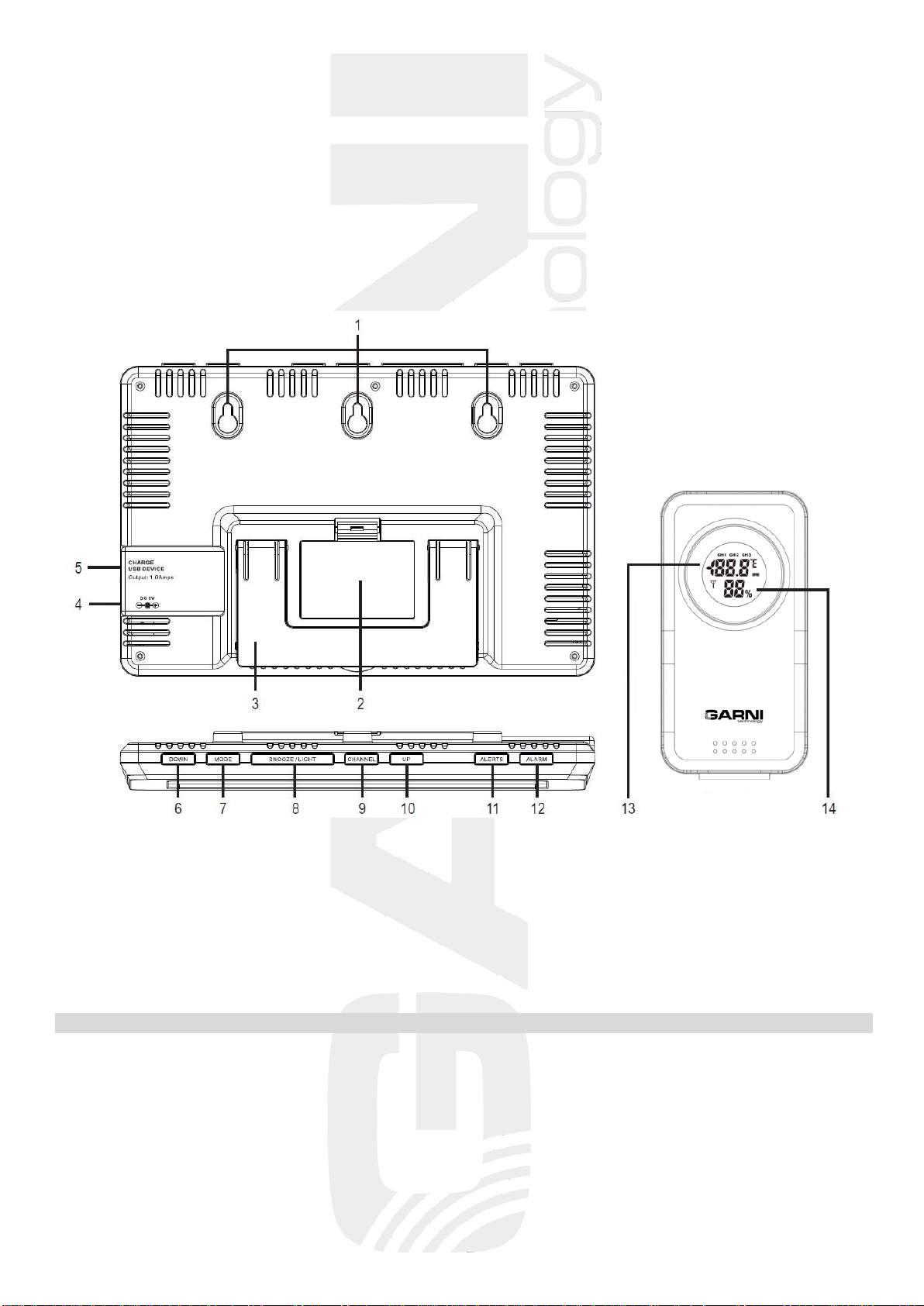
Rear side and the main unit buttons, wireless sensor
1) Mounting holes
2) Battery compartment
3) Folding stand
4) Power adapter socket
5) USB charging port
6) DOWN button
7) MODE button
8) SNOOZE/LIGHT button
9) CHANNEL button
10) UP button
11) ALERTS button
12) ALARM button
13) No. of selected channel; outdoor temperature
value; battery icon
14) Relative outdoor humidity value; signal icon
DEVICE STARTUP
Installing the batteries of the main unit
Note: to avoid deleting settings, connect the AC adapter before replacing the batteries
1) The main unit can be battery-powered (display illumination may be short-lived), or
connected by an AC adapter (display illumination can be continuous).
2) Remove the battery compartment cover on the back of the main unit and insert three AAA batteries. Be
mindful of the correct battery polarity. The display lights up and briefly shows all display segments.
3) Close the battery compartment

4
The main unit can also be powered using the AC adapter even if the batteries are inserted.
Connect the AC adapter plug to the outlet on the side of the main unit and plug into the
wall socket.
When the main unit is put into operation, the wireless sensor signal reception is initiated. The icon flashes
on the main unit’s display . Scanning for the wireless sensor signal will take 3 minutes, after which icon
turns off. After successful signal reception, the measured values are shown on the display.
If the wireless sensor signal is lost, hold the CHANNEL button on the main unit for 3 seconds. The main
unit initiates re-scanning for the wireless sensor signal, icon flashes.
Installation of wireless sensor batteries
Note: to avoid damage to the weather station, be sure to check the correct polarity of the batteries.
For the main unit, use high quality alkaline batteries, and for the wireless sensor we recommend
lithium batteries that are resistant to frost. Do not use rechargeable batteries.
1) Remove the battery compartment cover on the back of the wireless sensor.
2) When using multiple wireless sensors, make sure that a different channel is set on each sensor using
the switching button for the channel selection (1, 2 or 3) located in the battery compartment.
3) Insert two AAA batteries. Signal transmission is indicated by the icon on the display that flashes
once in 57 seconds.
4) Close the battery compartment
Once the main unit is connected to the wireless sensor, place the main unit and the wireless sensor at the
desired location within the wireless sensor signal range.
If the batteries are discharged, the icon will appear on the display of the wireless sensor and the icon
on the main unit display in the outdoor section.
The connection must always be re-established after replacing the batteries.
Placement
Placement of the wireless sensor
To avoid measurement distortion, place the wireless sensor away from direct sunlight. We recommend
placement outside on the north wall. Obstacles such as walls, concrete, metal structures and large objects
reduce signal reach. For optimal signal transmission, place the wireless sensor vertically.
Obstacles (walls, trees) and other electrical devices (TVs, monitors, etc.) may impact the signal range.
You can hang the wireless sensor on a mounting hole or stand it up using the stand.
Main unit placement
Select a spot for the main unit away from direct sunlight. Before installation, test the connection with the
wireless sensor. If there is a signal reception problem, select a different location. The back of the main unit
has a hole for hanging. You can also place the main unit on a flat surface using a folding stand.
TIME AND DATE CONTROLLED BY THE DCF-77 RADIO SIGNAL
The weather station is equipped with a DCF-77 signal receiver for time and data management,
for signal transmitted from Frankfurt am Main, Germany with a reach of about 1500 km. Outside of this
range, it is possible to set time and date manually. Time and date setting take place every day.
If the time and date are set manually, they will be reset upon reception of the DCF-77 signal.
After inserting the batteries into the main unit, all segments of the display will appear for about 3 seconds,
and then the main unit will receive the wireless sensor signal. When the connection is established, the main
unit goes into the DCF-77 radio signal reception mode for time setup. The icon flashes during the
search.
5
If the signal is not received, the DCF-77 signal reception icon will not appear on the display. If the signal is
successfully received, the reception icon will be permanently shown on the display. DST means
daylight saving time.
Search for the DCF-77 signal is done daily at 01:00, 02:00 and 03:00 a.m. If the signal is not successfully
received at 03:00 a.m., the main unit will search for it at 04:00 and 05:00 a.m. Another search attempt
occurs the next day at the same time.
To start the search manually, press and hold the DOWN button for 3 seconds. To exit the search, briefly
press the DOWN button. The other buttons are inoperative during the search, except the SNOOZE/LIGHT
buttons.
Note: the DCF-77 signal receiver for time and date setup is integrated into the main unit, therefore
it is necessary to place the main unit in a way that guarantees good quality reception of the DCF-77 signal.
Reception of the DCF-77 signal is indicated by the icon on the main unit display.
THE WEATHER STATION SETUP
To enter the setup mode, press and hold mode the MODE button down in the main screen for
3 seconds.
button
setting
steps
press MODE for 3
sec.
entering the setup mode →
setting the time zone
Press the UP or DOWN button to change the time
zone (the setting for the Czech Republic and
Slovakia is 00)
press MODE
setting the clock
Press the UP button to increase value or DOWN
to reduce the set value
press MODE
setting the minute
Press the UP button to increase value or DOWN
to reduce the set value
press MODE
setting the year
Press the UP button to increase value or DOWN
to reduce the set value
press MODE
setting the month
Press the UP button to increase value or DOWN
to reduce the set value
press MODE
setting the day
Press the UP button to increase value or DOWN
to reduce the set value
press MODE
language settings
Press the UP or DOWN button to select the
desired language
press MODE
exit the setup mode
Note: By holding down the UP or DOWN button when setting a given value, you will increase or decrease
this value faster.
If no button is pressed for 8 seconds, the last set value will be stored and the setting mode will end.
Languages that can be set: ENG English, GER German, FRE French, ITA Italian, DUT Dutch, SPA Spanish,
DAN Danish.
Abbreviations of the day's name
ENG
GER
FRE
ITA
DUT
SPA
DAN
Monday
MON
MON
LUN
LUN
MAA
LUN
MAN
Tuesday
TUE
DIE
MAR
MSR
DIN
MAR
TIR
Wednesday
WED
MIT
MER
MER
WOE
MIE
ONS
Thursday
THU
DON
JEU
GIO
DON
JUE
TOR
Friday
FRI
FRE
VEN
VEN
VRI
VIE
FRE
Saturday
SAT
SAM
SAM
SAD
ZAT
SAD
LOR
Sunday
SUN
SON
DIM
DOM
ZON
DOM
SON

6
Setting a 12 or 24 hour time display
To select the time display in 12-hour or 24-hour format, press the DOWN button in basic view mode. If the
12-hour format is selected, the PM indicator will be displayed next to the time from 12:00 p.m. until 11:59
p.m.
Temperature units
To select the display of the measured temperature in degrees Celsius °C or Fahrenheit °F, press the UP
button in basic view mode.
Switching between wireless sensor channels
If multiple wireless sensors are paired with the main unit, press the CHANNEL button to display the
measured temperature and relative humidity values of individual wireless sensors.
If a double circular arrow is displayed, the measured values of all connected wireless sensors will gradually
be displayed on the main unit display.
Display backlight
The main unit allows you to adjust the display backlight intensity. To adjust it, press the SNOOZE/LIGHT
button in the basic display mode.
The display backlight has two levels of brightness and a turn-off option.
Only short-time backlighting for 8 s and two levels of brightness can be used with battery power. The main
unit is equipped with a sound sensor, and when powered by batteries only, the display can be illuminated
by sound, for example, tapping, clapping, etc.
Setting the alarm time
The weather station has the option to set two alarm times. In the basic display, select alarm time 1 by
pressing the MODE button (AL 1, default setting at 6:00 a.m.) or alarm time 2 (AL 2, default setting 0:00
a.m.). Then press the MODE button again and hold for 3 seconds. The hour digits begin to flash.
Use the UP or DOWN buttons to set the desired alarm hour and confirm by pressing MODE.
The minute digits begin to flash. Use the UP or DOWN buttons to set the desired alarm minute.
Confirm the settings by pressing MODE.
If no button is pressed for 8 s during setup, the display will change to the basic display.
Snooze function
When the alarm signal is activated at the set time, press the SNOOZE/LIGHT button to interrupt and
postpone the alarm to a later time. The snooze time can be set from 3 to 20 minutes. Default setting
is 5 minutes.
To set the snooze time, press SNOOZE/LIGHT and hold for 3 s. The Zz symbol will appear in place of the
time display, and the digit 05 (the default 5-minute snooze setting) will flash.
use the UP or DOWN buttons to set the desired snooze minute within the range of 3.
to 20 minutes and confirm by pressing MODE.
If no button is pressed for 8 s during setup, the display will change to the basic display.
Turn on the alarm clock
In the basic display mode, press ALARM. Press one time to turn on alarm clock1, twice
to turn on alarm clock 2, three times to turn on alarm clocks 1 and 2, and switch off the alarm clock by
pressing the fourth time. Icons for respective alarms AL1 and AL2 are always shown on the display
Turning off the alarm signal
When the alarm signal is activated at the set time, you can activate the snooze function by pressing
SNOOZE/LIGHT. The Zz symbol will flash on the display. The alarm signal will be re-activated after the set
time.
7
To exit the snooze function, press any other button. If you don’t want to use the Snooze function, press any
button except SNOOZE/LIGHT to switch off the alarm signal.
If no button is pressed, the alarm signal will be turned off automatically after 2 minutes.
Setting alarm for upper and lower temperature limits
The weather station has the option to set the upper and lower limits of the indoor and outdoor temperature.
In the basic display mode, press ALERTS.
1 push
display of the upper limit (HI) of the outdoor temperature
2 pushes
display of the lower limit (LO) of the outdoor temperature
3 pushes
display of the upper limit (HI) of the indoor temperature
4 pushes
display of the lower limit (LO) of the indoor temperature
5 pushes
return to basic display
Turn the alarm on/off
When the upper or lower temperature limits are displayed, press the UP or DOWN button to turn the alarm
on or off. The on or off mode of the appropriate upper or lower temperature alarm will be indicated on the
display by the OFF symbol or the upper limit alarm HI , or the lower limit LO when they are on
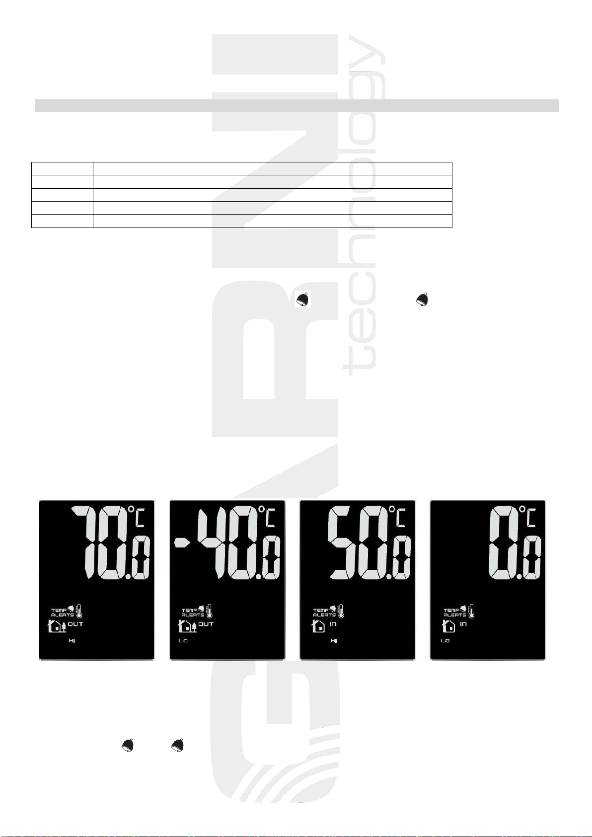
Setting values for upper and lower temperature limits
In the basic display, press ALERTS and hold it for 3 s. The upper limit of the outdoor temperature will flash.
Use the UP or DOWN buttons to set the desired value. By pressing
and holding these buttons the value will change more quickly. To confirm the setting, press ALERTS. The
value of the lower outdoor temperature limit will flash. Set the desired value in the same way. The setup
procedure is
- upper limit of outdoor (OUT) temperature (HI) –maximum 70°C
- lower limit of outdoor (OUT) temperature (LO) –minimum -40°C
- upper limit of indoor (IN) temperature (HI) –maximum 50°C
- lower limit of indoor (IN) temperature (LO) –minimum 0°C
If no button is pressed for 8 s during setup, the display will change to the basic display.
upp. limit of outdoor temp. low. limit of outdoor temp. upp. limit of indoor temp. low.limit of indoor temp.
Alarm activation
Reaching the set temperature limit will be signaled by an acoustic signal for about 5 s, with the
corresponding HI , or LO icon flashing on the display.
Press any button to turn off the acoustic signal
8
Note: - if the measured temperature is outside the measuring range, HH or LL will appear on the display
- if multiple wireless sensors are used, then the upper and lower temperature alarm can be set for
each sensor separately. Select the sensor with the CHANNEL button
TEMPERATURE DEVELOPMENT ARROW
The weather station displays arrows for indoor and outdoor temperature, namely an
increase, a steady state, or a decrease compared to previous measurements.
Charging your mobile device
The weather station has a USB port for the charging of mobile devices. You can only charge your mobile
device if the weather station is powered by an AC adapter.
Charging begins automatically when the mobile device is connected. Watch the charging process and
disconnect the cable from the USB port as soon as the mobile device is charged.
Note: The USB port delivers a maximum charging current of 1000 mA.
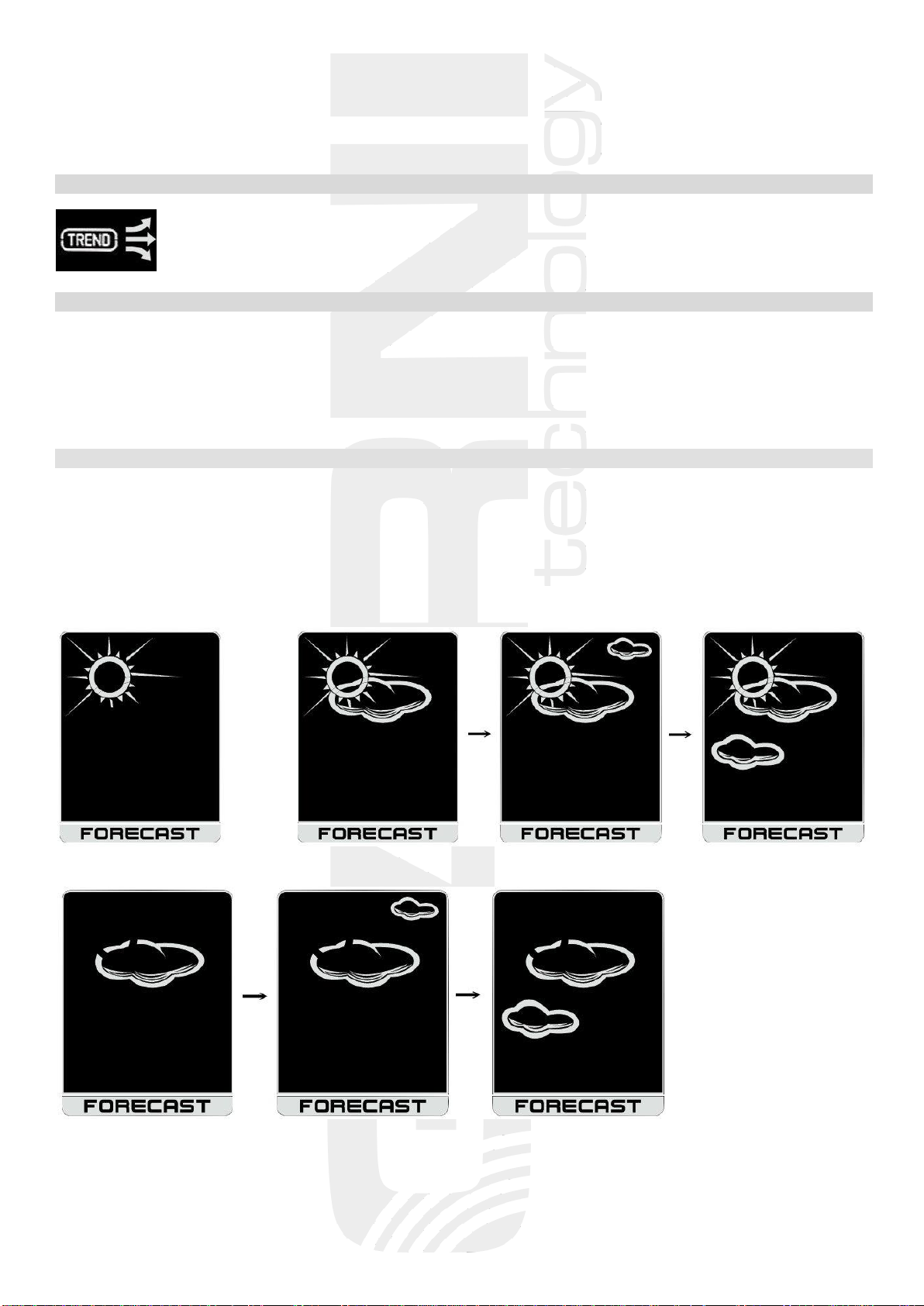
WEATHER FORECAST
The forecast is based on a change in barometric pressure; it generally applies that weather improves if the
pressure rises, and vice versa. The weather forecast is valid for the 30-50 km range with probability
of 70 to 75%
The weather forecast is shown with 13 icons in 6 levels - clear, partly cloudy, cloudy, rain, thunder
and snowfall.
clear almost clear semi-clear partly cloudy
cloudy partly overcast overcast

9
light rain rain scattered thunderstorms thunderstorms
light snowfall snowfall
Note: the snow icon will appear instead of the rainfall or storm icon if the outdoor temperature is lower
than 0°C.
LOW BATTERY INDICATIONS
Icon shown on the main unit display for the outdoor temperature and relative humidity indicates
low batteries in the wireless sensor, and for internal temperature and relative humidity values it indicates
low batteries in the main unit. It is necessary to replace the batteries with new ones.
TROUBLESHOOTING
problem / solution
connection failure between the main shorten the distance between the main unit
unit and the wireless sensor and the wireless sensor, or change their placement
metal structures, frames, etc. place the main unit and the wireless sensor so as to
between the main unit and the wireless sensor have as few obstacles as possible between them
shorten the signal range
the main unit or the wireless sensor are place the main unit and the wireless sensor further away
located near other electrical equipment from other el. equipment to avoid signal interference
the LCD display has a small contrast replace the batteries
temperature measured by the wireless sensor place the sensor away from direct sunlight and away
is too high from heating

10
SAFETY INFORMATION
• Do not expose the unit to excessive force, impact, dust, temperature or humidity
• Do not cover the ventilation holes with any objects such as newspapers, curtains, etc.
• Never immerse the device in water. If you spill liquid on the device, dry it immediately
with a lint-free cloth
• Do not clean the device with harsh or corrosive materials
• Do not manipulate the internal components of the device; otherwise, you will lose the warranty
• Use only new batteries. Do not mix old and new batteries
• Do not charge the batteries. Keep the station and its parts away from children
• Do not dispose of old batteries in unsorted municipal waste, but at designated locations
• Follow these instructions to dispose of this product
• Use only accessories specified by the manufacturer
• Do not interfere with the internal circuits of the device, or you may lose the warranty
• Technical specifications may change without prior notice
TECHNICAL PARAMETERS
Main unit
Power supply: AC adapter 100-240 V, 50/60 Hz, 0.3 A / 5 V, 1.2 A,
3 x AAA 1.5 V battery
Temperature measurement range: 0°C to +50°C
Measuring accuracy: +/- 1°C
Accuracy: 0.1°C
Humidity measurement range: 20% to 95%
Measuring accuracy: +/- 5%
Accuracy: 1%
Dimensions: 212 x 139 x 26 mm
Wireless sensor GARNI 040H
Power supply: 2 x AAA 1.5 V batteries
Temperature measurement range: -30°C to +60°C
Measuring accuracy: +/- 1°C from 0°C to 50°C; +/- 2°C for other range
Accuracy: 0.1°C
Humidity measurement range: 20% to 95%
Measuring accuracy: +/- 5%
Accuracy: 1%
Transmission frequency: 433 MHz
Maximum RF power: 7 dBm (5 mW)
Data transfer interval: 57, 67, 79 s (depending on selected channel)
Coverage: IPX3
Space range: up to 40 m in open space
Dimensions: 89 x 45 x 27 mm
GARNI technology a.s. declares that the type of radio device - weather station model GARNI 560 EASY II
- is in compliance with Directive 2014/53/EU. The full text of the EU Declaration of Conformity is available on the
following website: www.garni-meteo.cz
The instruction manual translated, edited, and processed by Ondřej Gajda for GARNI technology a.s.
Copying this instruction manual or its parts without the author's permission is forbidden
Version 1.2
Table of contents
Other GARNI Weather Station manuals

GARNI
GARNI GARNI610 Precise User manual

GARNI
GARNI 545 line User manual

GARNI
GARNI 635EL User manual

GARNI
GARNI WS6650 User manual

GARNI
GARNI 525 User manual

GARNI
GARNI GARNI 570 EASY II User manual

GARNI
GARNI 940 User manual

GARNI
GARNI 1233 User manual

GARNI
GARNI ND5010 User manual

GARNI
GARNI 365 ARCUS User manual


Popular Weather Station manuals by other brands


Bresser
Bresser Tendence FSX instruction manual

UCTECH
UCTECH FT0365 user manual

Jaycar Electronics
Jaycar Electronics XC0349 instruction manual

La Crosse Technology
La Crosse Technology WS-9133BK-IT Quick setup guide

La Crosse Technology
La Crosse Technology S88907V2 instruction manual

Oregon Scientific
Oregon Scientific BAR916HG user manual