GARNI 545 line User manual

INSTRUCTION MANUAL FOR WEATHER STATION
MODEL Line
Line
SYMBOLS
This symbol is followed by an important notice, this symbol is followed by a note
For safe use, always follow the instructions in this documentation
PACKAGE CONTENTS
Main unit (receiver)
Wireless sensor GARNI 030H
AC adaptor for the main unit
Manual
DESCRIPTION
- inverse color display
- measurement of outdoor and indoor relative humidity (%)
- measurement of indoor and outdoor temperature (°C, or °F)
- possibility to connect up to 3 wireless sensors for measurement of temperature and relative humidity at
different spots
- alarm for upper and lower limits of the outdoor temperature
- frost indication
- 5 icons of indoor thermal comfort
- weather forecast icons based on monitoring of changes in barometric pressure
- absolute barometric pressure display
- memory for maximum and minimum readings of temperature and rel. humidity
- time and date controlled by DCF-77 radio signal with manual setting option
- 12- or 24-hour time display format
- alarm clock
- Moon phase
- repeated 5-minute snooze function
- permanent display backlight option when on mains power, 4 backlight brightness levels, option to turn off
display backlight
- USB port for powering external devices
- the main unit and the wireless sensor can be suspended or stand
- the wireless sensor is included in the delivery
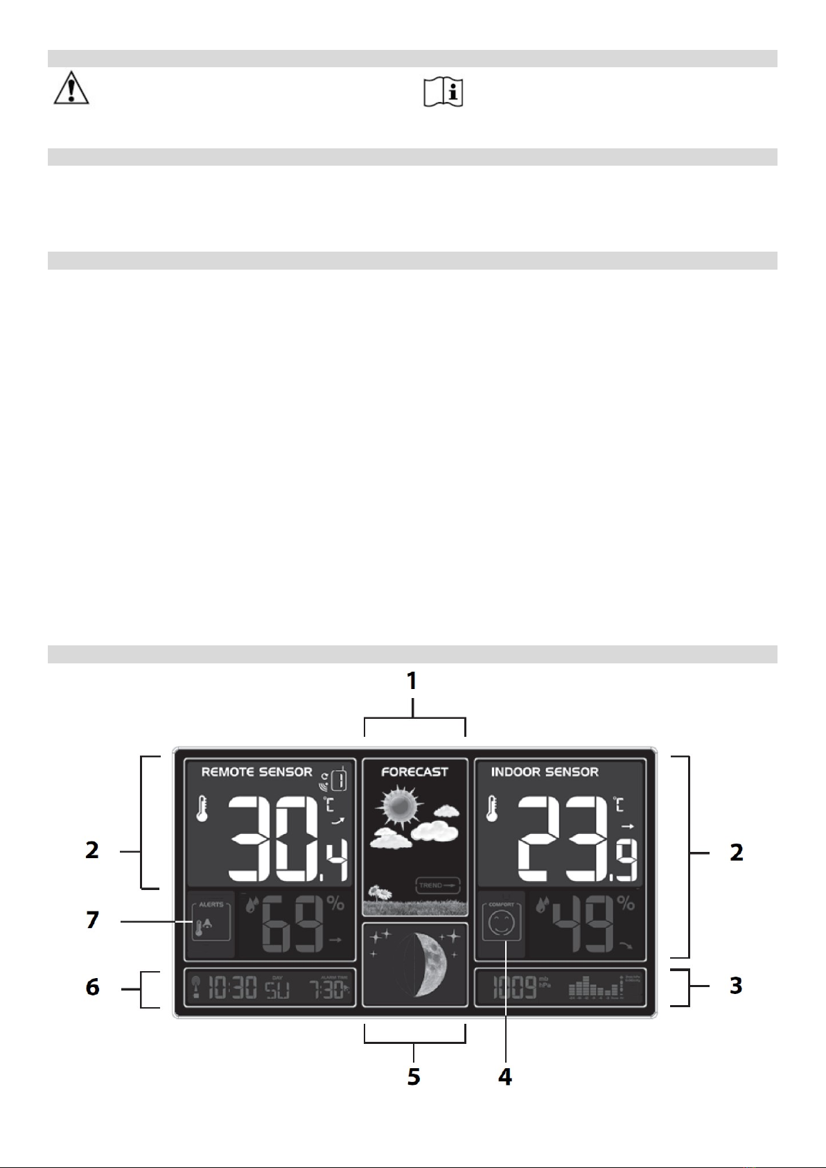
Main unit
Front view
2

1) The icon of weather forecast and weather trend
2) Temperature and relative humidity (REMOTE SENSOR – outdoor, INDOOR SENSOR – indoor)
3) Absolute barometric pressure and chart of barometric pressure trend
4) Thermal comfort icon
5) Moon phase
6) Time and date
7) Icon for alarm for the upper and lower temperature limit
Rear view
8) Wall suspension hole
9) Button
- brief display backlight
- snooze activation
10) Main unit stand
11) Battery compartment
12) AC adaptor socket
13) USB port for powering
external devices (like
mobile phones etc.)
Side view
14) Button
- entering manual setting of time and date
- saving settings
- switching between displaying seconds and date
15) Button
- saving wake-up time
- switching between displaying set wake-up time and date
16) Button
- increase set value
- switching between display of the temperature readings in
degrees Centigrade (°C) or Fahrenheit (°F)
- manual start/stop of reception of the DCF-77 signal
17) Button
- decrease set value
- display of readings from individual wireless
sensors
- manual start of reception of the wireless sensor signal
18) Button
- activating the alarm for the upper and lower temperature limit
- setting the upper and lower limits of the outdoor temperature
19) Button
- setting of backlight brightness (4 levels)
- change of barometric pressure units
20) MEM button
- displaying/erasing the maximum and minimum readings
21) ON/OFF button
- activation/deactivation of the alarm clock
3

4
Wireless sensor
1) Temperature
2) Relative humidity
3) LED
4) °C/°F button
5) Broadcast button TX
6) Channel switch
7) Battery compartment cover
COMMISSIONING
Battery installation
Note: observe the correct battery polarity to prevent damage to the weather station. Use quality
alkaline batteries for the main unit; we recommend using lithium batteries for the wireless
sensor due to their resistance to frost. Do not use rechargeable batteries. Do not expose
the batteries to high temperatures like fire or direct sunlight
Main unit
The main unit can be powered by batteries (short-time display backlight for 15 seconds will be possible) or
by an AC adaptor (permanent display backlight will be possible). If the main unit is powered by an adaptor,
the batteries are not being used, therefore you should remove them to avoid damage to the batteries and to
the main unit. Use only the delivered AC adaptor.
Powering with AC adaptor
1) Connect the AC adaptor plug into the socket on the rear side of the main unit.
2) Connect the other side of the AC adaptor to a mains socket.
Battery power
1) Remove the battery compartment cover on the rear side of the main unit.
2) Insert 2 pcs AA (mini) batteries, observe the correct polarity.
3) Close the battery compartment.
After connection to the power supply, a beep sounds and the wireless sensor signal reception icon next
to the REMOTE SENSOR number flashes for 3 minutes.
Wireless sensor
1) Remove the battery compartment cover on the rear side of the wireless sensor.
2) Set the required channel using the switch in the battery compartment.
3) Insert 2 pcs AA (mini) batteries – observe the correct polarity.
4) Push the TX button. A beep sounds and the temperature readings from the wireless sensor are
displayed on the main unit display
5) Close the battery compartment.
5
Once the connection of the main unit to the wireless sensor is established, place the main unit
and the wireless sensor in the desired location within the range of the wireless sensor signal
Using multiple wireless sensors
The main unit allows to connect up to 3 wireless sensors which can be placed at different spots. Each
wireless sensor must be assigned its own channel number (1, 2 and 3).
1) Place the main unit and the wireless sensor next to each other.
2) Remove the battery compartment cover on the side of the wireless sensor.
3) Assign a number to each wireless sensor using the switch so that the numbers are unique.
4) Insert 2 pcs AA (mini) batteries, observe the correct polarity. Then push the TX button. A beep sounds
and the temperature readings from the wireless sensor are displayed on the main unit display.
5) To display the readings from a given wireless sensor, select the desired channel on the main unit using
button .
To automatically change the channel in ascending order, press button repeatedly until next to the
channel number a small arrow wheel appears. The main unit will alternate between displaying the
readings from all wireless sensors.
The reception of the wireless sensor signal can be also started manually by pushing and holding button
for 3 seconds.
Placement of the weather station
Main unit
Select the location of the main unit away from direct sunlight. Test the connection to the wireless sensor
before final installation. If there is a problem with the signal reception, select another location. There is a
mounting hole for suspension on the rear of the main unit. You may also put the main unit on a flat surface
using the folding support. Placement near TVs, monitors, computers, etc. may negatively affect the
reception of the DCF-77 signal and the wireless sensor signal.
Wireless sensor
Place the wireless sensor away from direct sunlight not to compromise the measurement. Placement
outdoors, at the northern wall is recommended. Obstacles such as walls, concrete, metal structures and
large objects reduce the signal range. Position the wireless sensor vertically for optimum signal
transmission. Maximum open space signal range is 60 meters.
The signal range may be affected by obstacles (walls, trees) and other electrical devices (TVs, monitors,
etc.).
Time controlled by the DCF-77 radio signal
The weather station is equipped with the DCF-77 time/date control signal receiver, the signal is
broadcasted by a transmitter from Frankfurt am Main, Germany, with a range of about 1500 km. When
outside this range, the time and date can be adjusted manually. The time and date are adjusted every day.
When the batteries are inserted or the AC adaptor is plugged to the main unit, the display lights up, all
display segments are briefly displayed, and a beep sounds and the wireless sensor signal reception
commences.
After the connection with the wireless sensor has been established, the reception of the DCF-77 is
commenced, indicated by flashing icon . This process may take several minutes. The display will be off
during the reception of the DCF-77 signal and the functionality of the main unit will be limited. Only buttons
and will function. When the signal is received successfully, the display shows the current time,
date and signal reception icon. The icon shows the signal reception strength, the more bars the better
the signal. The weather station will automatically receive the DCF-77 signal for time adjustment every day
at 1:00, 2:00 and 3:00. If reception is unsuccessful, reception will be attempted again in another hour, five
6
times in total. The received time is compared with the time on the main unit and adjusted if necessary. For
better signal reception, place the main unit near a window.
If the DCF-77 signal is not received (icon is not displayed), reception will be interrupted, and it will be re-
attempted in an hour until the DCF-77 signal is received successfully.
Note:
The received DCF-77 time adjustment signal strength may be affected by the geographical location or the
premises where the weather station is located.
For better reception, the main unit should be placed on a flat non-metallic surface, near a window on the
upper floor of your house away from electrical appliances such as a TV, computer, etc.
Manual reception of the DCF-77 signal
Press and hold button until the icon is displayed and the manual search for the DCF-77 commences.
If reception is unsuccessful, the icon disappears, and the time is not adjusted automatically. After
successful signal reception, the time and date will be adjusted even if they were manually set before.
No data on display
Reception of the DCF-77 signal not successful
1.
Check that the DCF
-
77 is available at your location.
2.
Start searching for the signal manually.
3. Wait until the main unit automatically restarts the search.
4.
Set time and date manually.
Wireless sensor signal reception not successful
1.
Check that the batteries in the wireless sensor are inserted correctly.
2. Check that the wireless sensor is within the signal range.
3.
Press and hold button
to
st
art signal search manually.
Manual setting of time and date
1) Press and hold button until the text “12-” and “24-” (time format) flashes.
2) Press button or to set the 12-hour or 24-hour time format.
3) Press button to save and move to the next setting.
4) Press button or to select the time zone (for the Czech and Slovak Republic it is 00).
5) Press button to save and move to the next setting.
6) Press button or to set the hour.
7) Press button to save and move to the next setting.
8) Press button or to set the minute.
9) Press button to save and move to the next setting.
10) Press button or to select the date format (D-M, day-month or M-D, month-day).
11) Press button to save and move to the next setting.
12) Press button or to set the year.
13) Press button to save and move to the next setting.
14) Press button or to set the month.
15) Press button to save and move to the next setting.
16) Press button or to set the day.
17) Press button to save and move to the next setting.
18) Press button or to select the language for day names.
19) Press button to save and move to the next setting.

7
Note: If no button is pressed for 20 seconds, the setting mode will be terminated.
Day name abbreviations
Monday
Tuesday
Wednesday
Thursday
Friday
Saturday
Sunday
GE - German MO DI MI DO FR SA SO
EN
-
English
MO
TU
WE
TH
FR
SA
SU
FR - French LU MA ME JE VE SA DI
IT
-
Italian
LU
MA
ME
GI
VE
SA
DO
SP - Spanish LU MA MI JU VI SA DO
DU
-
Dutch
MA
DI
W
O
DO
VR
ZA
ZO
DA
-
Danish
MA
TI
ON
TO
FR
LO
SO
DESCRIPTION OF THE MAIN UNIT DISPLAY
Time and date
1) DCF-77 signal reception icon
2) Current time in the 12- or 24-hour time format;
for the 12-hour time format, the hours before noon
will be indicated as “AM” and the afternoon hours as “PM”
3) Current day of the week
4) Displaying the set wake-up time; pressing button or
switches between displaying the day and month, seconds and the set wake-up time
5) Alarm-clock on icon
Indoor / outdoor temperature and relative humidity
Remote sensor – the readings of the outdoor quantities from the wireless sensor / sensors
Indoor sensor – the indoor readings measured by the main unit
1) Temperature unit (°C or °F)
2) Temperature trend arrow
3) Temperature in degrees Centigrade °C
or Fahrenheit °F
4) Relative humidity
5) Relative humidity trend arrow
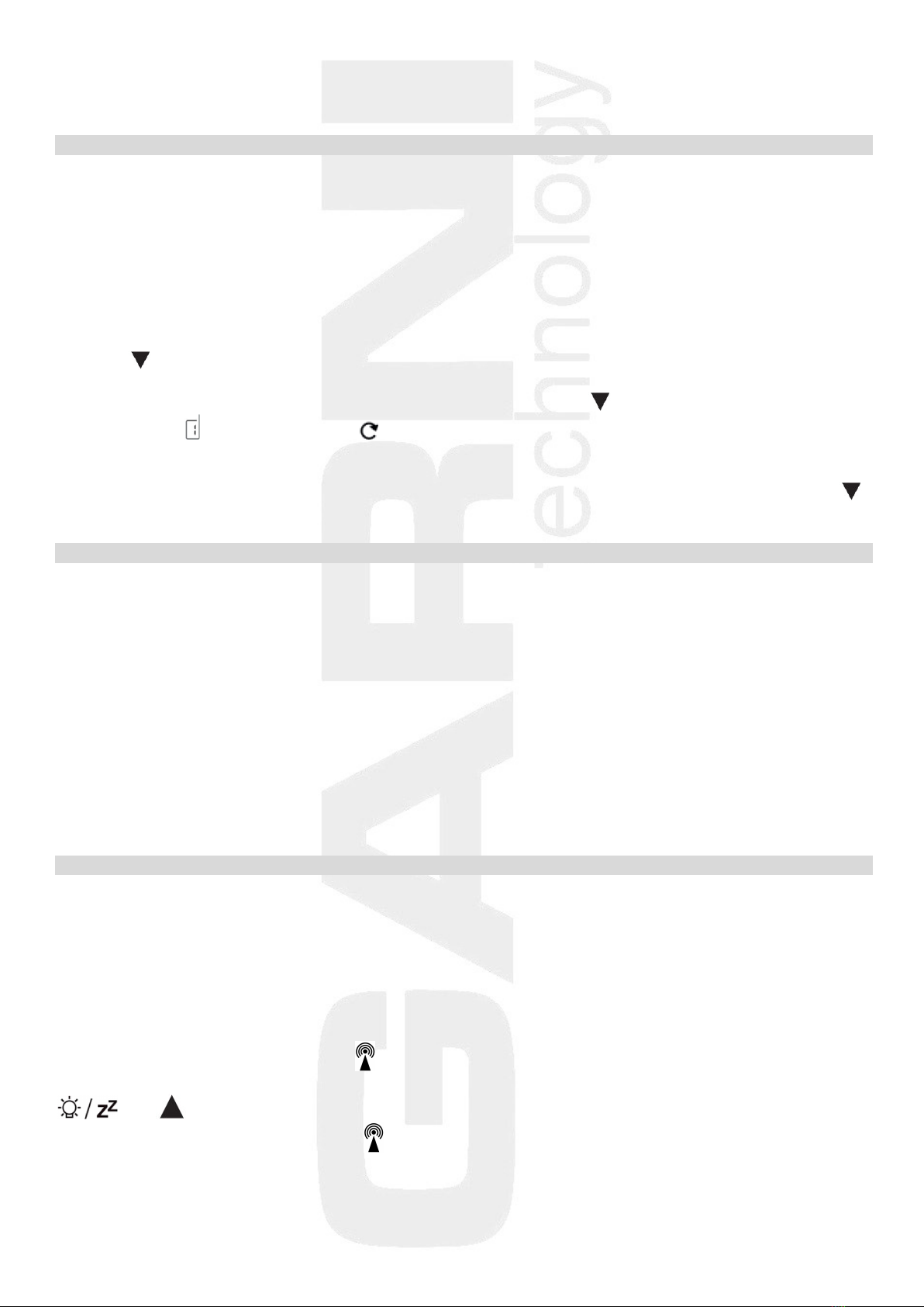
Weather forecast
The forecast is based on the change in barometric pressure, generally speaking when the barometric
pressure rises, the weather improves and vice versa. The forecast accuracy is 75% and is valid for the next
12 to 24 hours for the area within a radius of 30 to 50 km.
8
The weather forecast uses six icons – sunny, somewhat cloudy, cloudy, precipitation, heavy rain and snow.
Sunny Somewhat
cloudy
Cloudy Precipitation Heavy rain Snow
Note: the snow icon replaces the precipitation or heavy rain icons if the outdoor temperature from
the channel 1 sensor is below -4°C. If the channel 1 is not used, it is the temperature from
channel 2 sensor, if channel 2 is not used, then it is the temperature from the channel 3
sensor
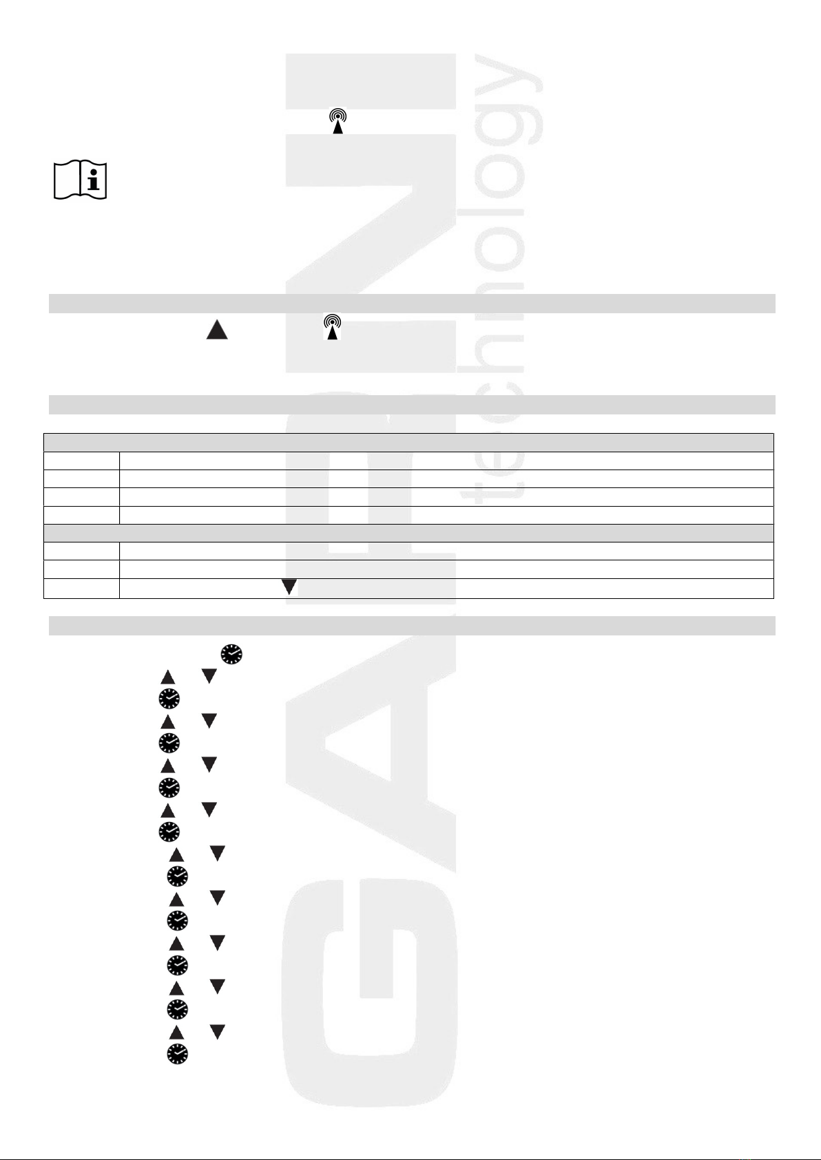
Weather trend arrows
The weather station updates the weather trend arrows and reflects changes that have taken place over the
last 3 hours of measurement.
Barometric pressure increased in
the last 3 hours
Barometric pressure unchanged in
the last 3 hours
Barometric pressure decreased in
the last 3 hours
E.g.: the weather forecast indicates rain, the barometric pressure drops abruptly and quickly , therefore
the probability of heavy rain is higher.
Arrows of temperature / relative humidity trends
The main unit displays the trend icons of the measured quantities based on the temperature and relative
humidity readings.
Temperature / relative humidity
increases
Temperature / relative humidity
unchanged
Temperature / relative humidity
decreases
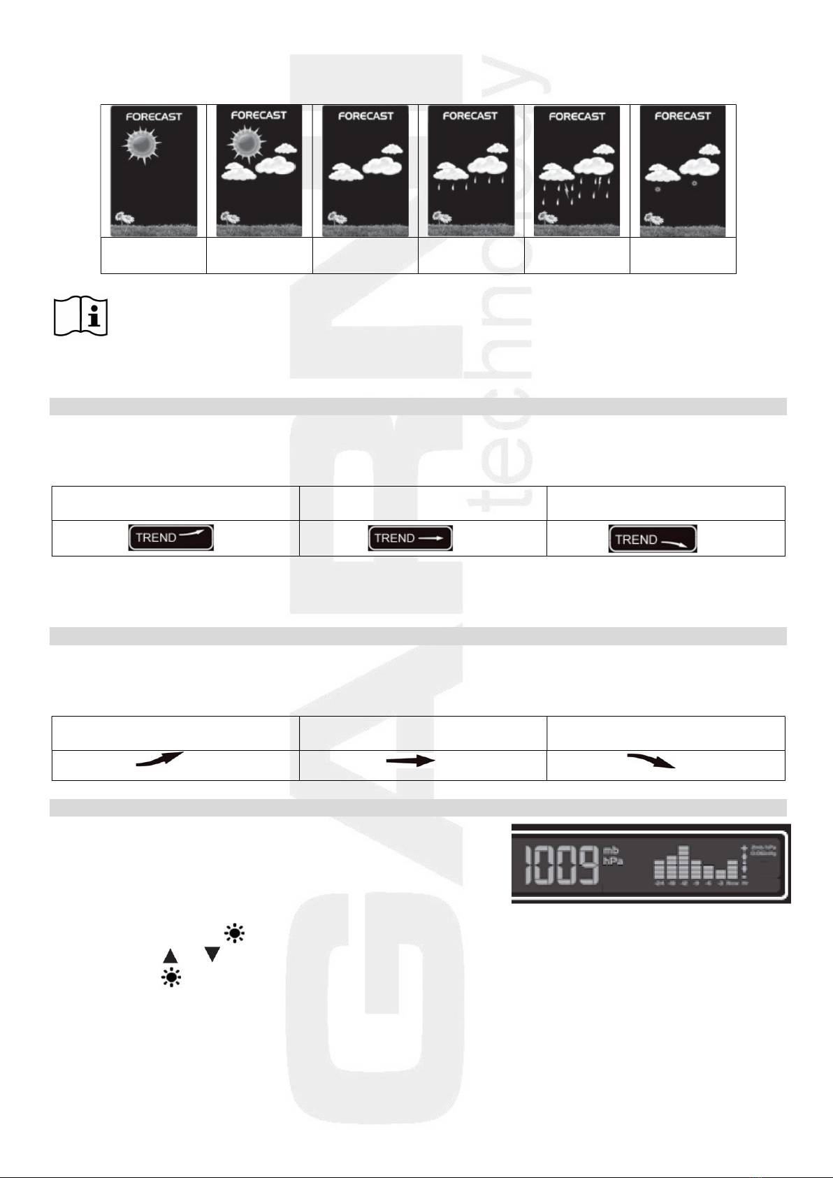
Absolute barometric pressure
The reading of the absolute barometric pressure is displayed
using the selected units on the right side of the display of the main
unit. The chart shows the trend over the last 24 hours.
To change the barometric pressure units:
1) Press and hold button until the barometric pressure units flash.
2) Press button or to select the required unit (mb, hPa or InHg).
3) Press button to confirm the setting.
9
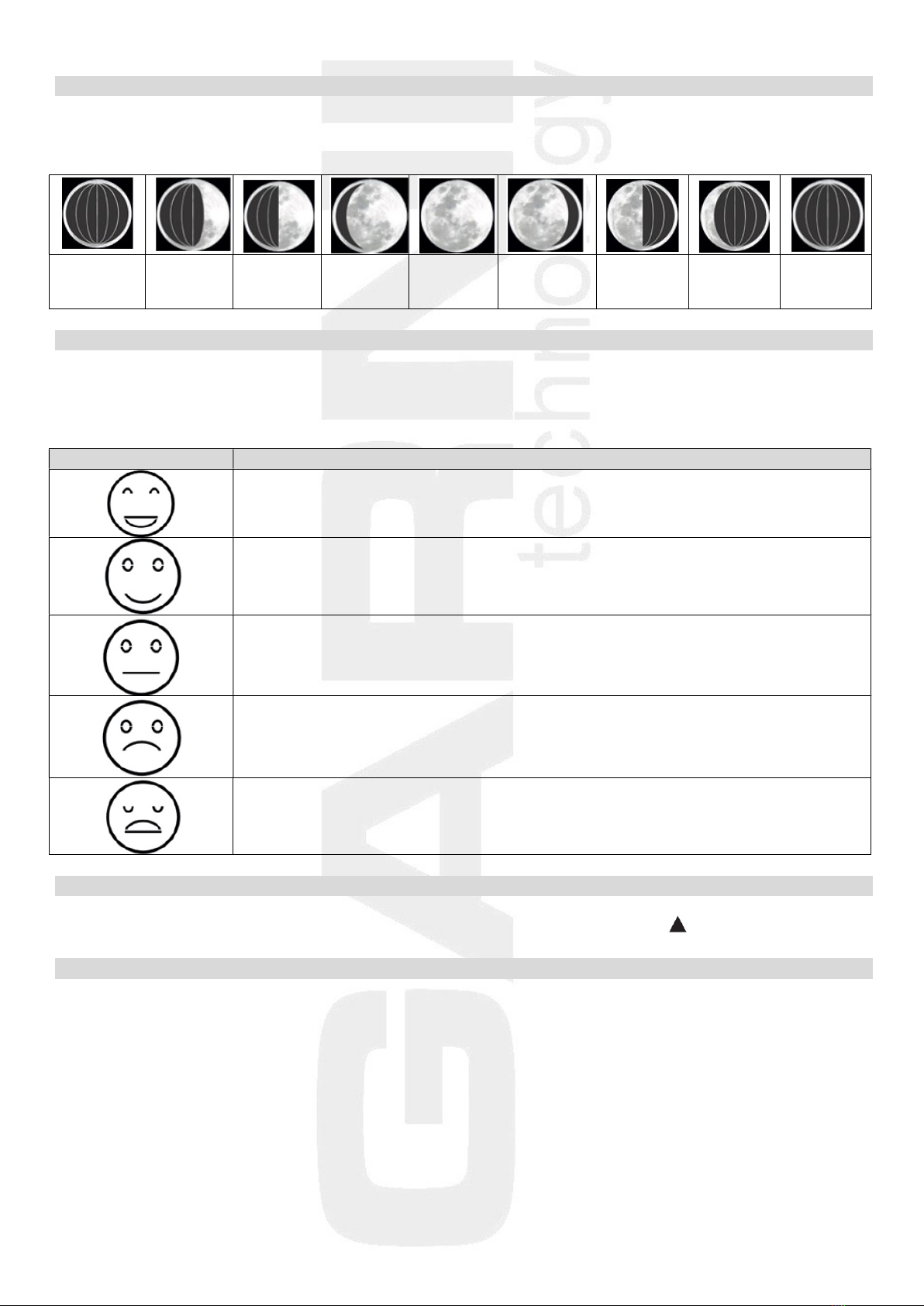
Moon phase
The weather station shows individual Moon phases according to the current date.
Displaying Moon phases on the northern hemisphere:
new Moon
(Moon is
not visible)
waxing
crescent
half-Moon
(first
quarter)
gibbous
(waxing)
full Moon gibbous
(waning)
half-Moon
(last
quarter)
waning
crescent
new Moon
(Moon is
not visible)
INDOOR THERMAL COMFORT ICONS
The thermal comfort is the feeling a person perceives in a given environment. The thermal comfort
condition in the given environment is shown on the basis of the readings of temperature and relative
humidity using 5 icons.
Icon
Temper
ature / Humidity
Temperature: very pleasant
Humidity: very pleasant
Temperature: pleasant
Humidity: pleasant
Temperature: higher or lower temperature than pleasant
Humidity: higher or lower humidity than pleasant
Temperature: unpleasant cold or hot
Humidity: unpleasant dry or wet
Temperature: too cold or hot
Humidity: too dry or wet
CHANGING THE TEMPERATURE UNITS
To change the temperature units to Centigrade °C or Fahrenheit °F press button .
DISPLAYING THE MAX. AND MIN. READINGS
Press the MEM button repeatedly to display the maximum and minimum readings of temperature and
relative humidity. The quantities will be displayed in the following order:
- maximum readings
- minimum readings
- the third push of the MEM terminates the browsing of the max. and min. readings, and the current
values are displayed
Press and hold the MEM button for 3 seconds to erase the stored readings. The memory is also
automatically erased at 00:00 every day.

10
ALARMS FOR THE UPPER AND LOWER LIMITS OF THE OUTDOOR TEMPERATURE AND FROST
INDICATION
Alarm for the upper and lower temperature limits
The weather station allows setting an alarm when a certain temperature between -20 °C and 60 °C is
reached. If more wireless sensors are used, the alarm can be set for each one separately.
Setting the temperature limit:
1) When more than one wireless sensor is used, select the desired channel using button
2) Press and hold button until the arrow and icon flashes
3) Press button or to set the required upper temperature limit
4) Press button to confirm the setting. Icon will flash
5) Press button or to set the required lower temperature limit
6) Press button to confirm the setting
Push button once to activate the alarm. Under the temperature reading, icon appears. As soon as
the set value is measured, a warning tone sounds and the icon flashes. Push any button to stop the alarm
signal. If the reading is above the set upper limit, the icon flashes, if it is below the set lower limit, the
icon flashes. The alarm will be activated until the temperature reading is outside the set limits, or until
the button is pushed.
To deactivate the function, press button , icon disappears.
Frost indication
The frost indication function and the set point alarm are closely linked, when the high and low temperature
alarm is active, the frost indication function is automatically activated.
As soon as the outdoor temperature is between -1°C and +3°C, the icon is displayed.
Note: Even if the icon is not displayed, remember that there is a risk of icing at temperatures
around zero and below.
SETTING THE WAKE-UP TIME
1) Press button , the display will show the wake-up time
2) Press and hold button for a few seconds until the wake-up hour flashes
3) Press button or to set the required wake-up hour
4) Press the button, the set wake-up minute flashes on the display
5) Press button or to set the required wake-up minute
6) Press button to confirm the setting
Activating and deactivating the alarm clock
To activate or deactivate the alarm clock slide the ON/OFF switch to the ON position (activated) or OFF
(deactivated). The alarm is activated if the icon is displayed.
To deactivate the activate wake-up alarm, push any button except .
To activate the SNOOZE function, push the button while the alarm is active, icons or will
flash and the alarm will be postponed for 5 minutes, and then reactivated. This process may be repeated.
If no button is pressed, the alarm with deactivate automatically after 2 minutes. The wake-up alarm will be
repeated after 24 hours at the set time.
11
CHANGE TO / FROM DAYLIGHT SAVING TIME
The change to / from daylight saving time is done automatically as long as the reception of the DCF-77
signal is successful. If the daylight saving time is displayed, the display shows DST.
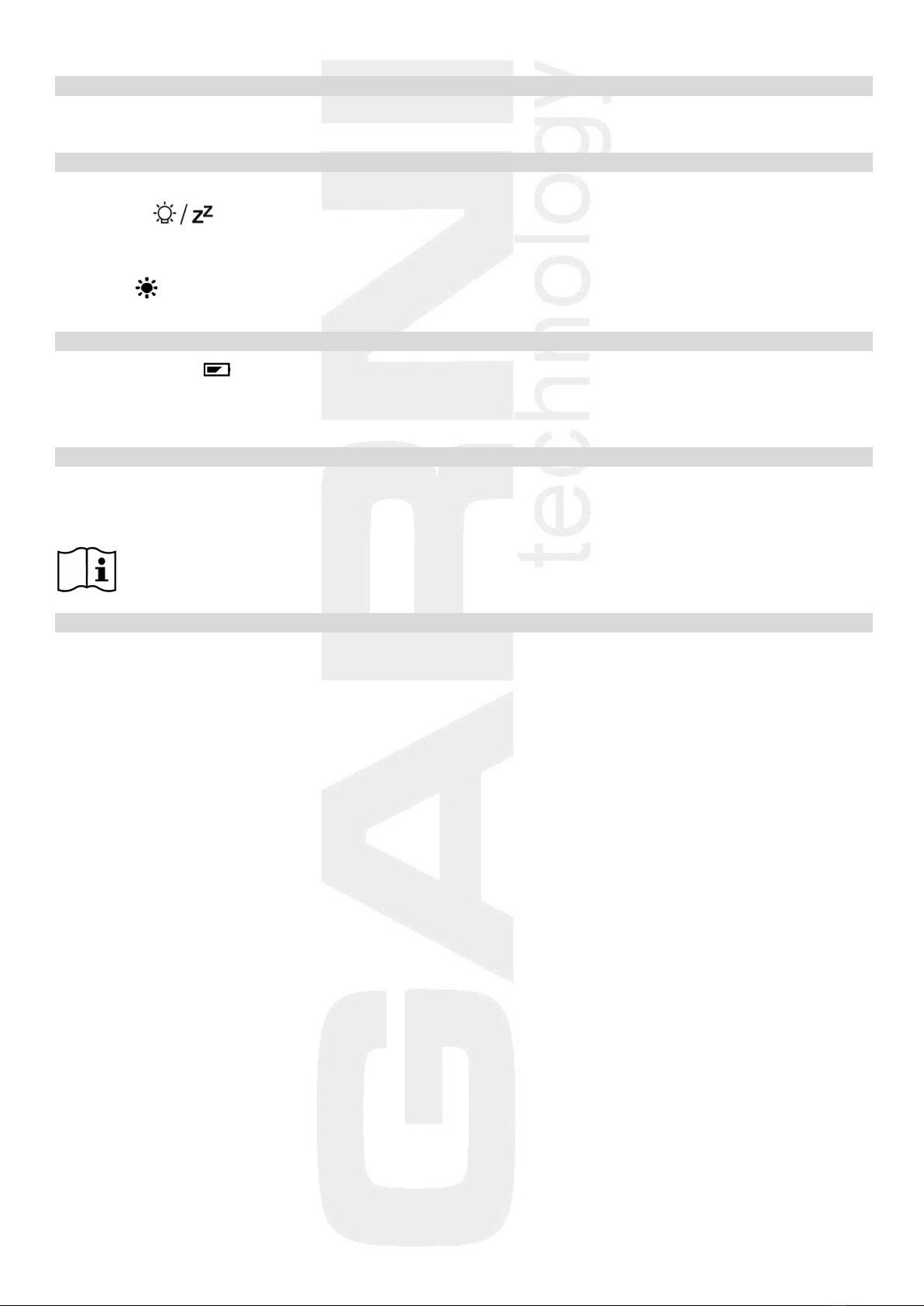
DISPLAY BACKLIGHT
Battery power
Push button to turn on the display backlight for 15 seconds.
Powering with AC adaptor
If the main unit is powered by the AC adaptor, the display backlight may be permanently on or turned off.
Press the button on the side of the main unit repeatedly to select the backlight brightness in
4 brightness levels and turning off the display backlight.
Empty battery icons
Empty battery icon on the main unit display:
- in the indoor quantities area – the main unit batteries are empty
- in the outdoor quantities area – batteries of the wireless sensor are empty
CHARGING DEVICES FROM USB
Devices such as mobile phones, mp3 players, etc. can be charged via the USB port located on the rear of
the main unit. Connect the device with a USB cable (not part of delivery). Follow the connected device
manufacturer's instructions. The USB port can only supply a charging current of 1,000 mA.
Note: the main unit must be powered by the AC adaptor while charging the device.
TROUBLESHOOTING
problem / situation solution
DCF-77 signal not received relocate the main unit; start the manual signal search;
set the time and date manually
instead of temperature and humidity readings temperature readings are outside the measurable range
the display shows: H.HH or LL.L
the weather station is not working correctly reset the factory settings of the main unit by removing
the batteries and disconnecting the AC adaptor for
30 seconds
intermittent connection between reduce the distance between the main unit
the main unit and the wireless sensor and the wireless sensor or relocate them
between the main unit and the wireless sensor relocate the main unit and the wireless sensor so that
there are metal structures, frames etc. there are minimum obstacles between them which
reduce the signal range
the main unit or the wireless sensor are relocate the main unit and the wireless sensor further
located close to other electrical devices away from other electrical devices to prevent signal
interference
the current time on the main unit a wrong time zone was probably selected
differs by one, two, three etc. hours
the temperature reading from place the sensor away from direct sunlight and
the wireless sensor is too high heating
12
SAFETY PRECAUTIONS
• Do not expose the device to excessive force, shocks, dust, temperature and humidity
• Do not cover the ventilation holes with any objects like newspapers, curtains, etc.
• Never immerse the device in water. If you spill liquid on it, dry it immediately with a soft, lint-free cloth
• Do not clean the device with abrasive or corrosive substances
• Do not handle the internal components of the device, as this will void your warranty
• Use only fresh batteries. Never mix fresh and old batteries
• Do not recharge the batteries. Place the station and its parts outside the reach of children
• Do not throw old batteries to unsorted municipal waste, but use the designated areas
• Dispose of this product in accordance with applicable regulations
• Use only accessories specified by the manufacturer
• Do not interfere with the internal circuits of the device, as this may void the warranty
• The technical specifications are subject to change without notice
TECHNICAL PARAMETERS
Main unit
Power supply: AC adaptor 100-240 V, 50/60Hz, 0,3 A / 5V, 1,2 A
2 pcs of 1.5 V AA batteries (mini)
Temperature measurement range: -9,9°C to +50°C
Accuracy of measurement: +/- 1°C
Resolution: 0.1°C
Rel. humidity measurement range: 20% to 95%
Accuracy of measurement: +/- 5%
Resolution: 1%
Absolute barometric pressure measurement range: 600 hPa/mb to 1100 hPa/mb
Dimensions: 205 x 130 x 30 mm
Wireless sensor GARNI 030H
Power supply: 2 pcs of 1.5 V AA batteries (mini)
Outdoor temperature measurement range: -40°C to +70°C
Accuracy of measurement: +/- 1°C
Resolution: 0.1°C
Rel. humidity measurement range: 20% to 95%
Accuracy of measurement: +/- 5%
Resolution: 1%
Data transmission frequency: 433.92 MHz
Number of channels: 3
Maximum RF power: 10 dBm (10 mW)
Wireless sensor signal range: up to 60 m (in open space)
Measurement interval: about 69 s
Dimensions: 49 x 95 x 32 mm
GARNI technology a.s. hereby declares that the type of the radio equipment - weather station type GARNI 545
Line conforms to the Directive 2014/53/EU. The full EU Declaration of Conformity is available on the following
website: www.garni-meteo.cz
The manual was prepared for GARNI technology a.s. by Roman Gajda.
Reproduction of this manual or its parts is prohibited without the author's consent
Version 03G20
This manual suits for next models
1
Table of contents
Other GARNI Weather Station manuals

GARNI
GARNI 550 EASY User manual

GARNI
GARNI 365 ARCUS User manual

GARNI
GARNI WS6650 User manual

GARNI
GARNI ND5010 User manual

GARNI
GARNI GARNI610 Precise User manual

GARNI
GARNI 560 EASY II User manual

GARNI
GARNI 1233 User manual

GARNI
GARNI 281 User manual

GARNI
GARNI 525 User manual

GARNI
GARNI 635EL User manual


