Gates C300 User manual

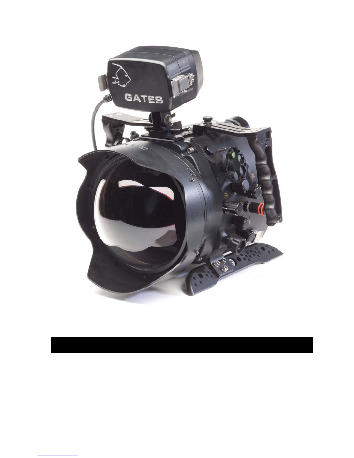
C300 / C500 Underwater Housing
Setup, Use, and Care Guide

Cautions Page 2
Copyright 2012, Gates Underwater Products, Inc.
Last document revision: September 27, 2012
Photo by Lee Peterson / Marine Camera Distributors and John Ellerbrock
This manual and current revision is available in 8.5 x 11 size and full color at
http://www.gateshousings.com/documentation.html
Gates Underwater Products, Inc.
13685 Stowe Drive
Poway, California 92064 USA
Phone: 800.875.1052 toll-free in the U.S.
858.391.0052 outside the U.S.
Fax: 858.391.0053
Web: GatesHousings.com

Cautions Page 3
Table of Contents
Setup, Use, and Care Guide.............................................. 1
Introducing C300/C500...................................................... 4
Features............................................................................. 4
Warranty Disclaimer .......................................................... 4
Unpacking C300/C500....................................................... 5
1: Cautions............................................................................. 6
2: C300/C500 Setup .............................................................. 7
C300/C500 Housing Preparation....................................... 7
EOS-C300 and C500 Camera Preparation ..................... 11
Camera / Lens Installation ............................................... 12
Lens Gear Drives (LGD’s) ............................................... 16
Video Connections (Optional).......................................... 19
Water Alarm (Optional) .................................................... 19
Gemini RAW External Recorder (Optional) ..................... 21
Check Operation.............................................................. 25
Front Bulkhead, Port and Port Ring................................. 26
Housing Closure .............................................................. 29
Seal Check ...................................................................... 33
Video Connections (Optional).......................................... 33
Final Checks .................................................................... 34
3: C300/C500 Operation...................................................... 35
Right Side / Rear Controls ............................................... 35
Left Side Controls ............................................................ 36
Buoyancy Adjustment ...................................................... 38
Adjustable Handles.......................................................... 41
Carry Handle.................................................................... 41
Port Options..................................................................... 42
Tripod Mount (Optional)................................................... 43
Tripod Legs (Optional) ..................................................... 44
Lighting Systems ............................................................. 45
Controlling Reflections..................................................... 45
Travel / Transport ............................................................ 45
4: C300/C500 Maintenance ................................................. 47
Housing Care and Maintenance ...................................... 47
O-Ring Care and Maintenance ........................................ 48
5: Customer Support............................................................ 49

Cautions Page 4
Introducing C300/C500
Congratulations on owning a new Gates product: the C300/C500 housing. You’ve
selected an underwater imaging tool that will provide years of value and reliable service.
We designed C300/C500 specifically for the Canon EOS-C300 and EOS-C500 digital
cinema cameras.
Please read through this entire guide to learn about C300/C500 so you can get the most
out of this imaging tool. In this section, we’ll introduce you to the features of C300/C500
so you can get started.
Features
C300/C500 has several key features:
Lens flexibility. C300/C500 can accommodate a variety of different cinema and
Canon DSLR lenses with no change to control locations. Focus, Iris, Zoom remain
in the same location regardless of optics used.
Full camera control. All practical controls are accessed directly with the
C300/C500 housing, as is the full menu system of the camera.
Cinema-grade design. Lens choice and control access are just two of the many
features designed into C300/C500. A/R coated glass optics, HD-SDI surface feed,
and Seal Check are a few of the items any professional will appreciate.
Warranty Disclaimer
C300/C500 is a tool that, like any tool, requires knowledge and understanding to be
effective.
Your responsibility is to learn the proper setup, use and care of C300/C500. Because
we can only provide you with the information necessary to do so, Gates does not
warrant the contents of your housing (e.g. your camera and lenses) under any
circumstance.
We warrant C300/C500 as an image acquisition tool for a period of 2 years. The Seal
Check unit is warranted for 1 year. Optics (Dome and Flat ports) are warranted for a
period of 1 year or 100 hours salt water contact, whichever comes first.
Gates does not warrant optical performance or image quality.
If you have any questions about the setup, use and care of C300/C500, contact Gates
directly. Details are in section 5.

Cautions Page 5
Unpacking C300/C500
After you remove C300/C500 from its shipping container, carefully inspect it for missing
parts or damage that may have occurred during shipment. If you discover any
discrepancies, contact Gates or your dealer immediately for assistance.
Standard Parts
C300/C500 Housing.
Camera Mount.
Lens Gear Drives (2x Clockwise
and 1x Counter Clockwise).
Hard Sided Rolling Case(s).
Seal Check system.
Tool Kit with case.
Various assembly and spare
parts for C300/C500 including
bolts, set screws and o-rings.
Spare O-Ring Kit.
Carry Handle.
Trim Weights (quantity
dependent on configuration).
Port Extender(s) of choice for
your lens.
Port(s) of choice (Dome, either
glass or acrylic, or Flat) and
shade.
Focus / Iris Indicator Rings.
Guide Bars and acetyl drive
shafts for your lens of choice.
Optional Parts
Microphone or Hydrophone.
Water alarm.
HD-SDI surface feed bulkhead connector and cable.
Light System.
External Monitor.

Cautions Page 6
1: Cautions
TRANSPORT. NEVER ship or transport your C300 or C500 camera inside the
C300/C500 housing. The housing was not designed for this purpose and severe
damage may result.
USER RESPONSIBILITY. This Setup, Use and Care guide contains important
detailed procedures for setup and use of C300/C500. It is the user’s responsibility to
read, understand and employ these procedures. Failure to do so can result in poor
or non-operation of C300/C500 and may void your warranty.
Contact Gates if you have questions this manual or using C300/C500.

C300/C500 Setup Page 7
2: C300/C500 Setup
C300/C500 requires complete and thorough setup prior to use.
C300/C500 Housing Preparation
Port. Remove the Port by rotating 90 degrees Counter Clock Wise (CCW) direction
while facing the front of the housing. Gently pull the Port away from the Port Ring
or Front Bulkhead.
TIP: Liberal lubrication of the Port o-ring allows easy rotation during
installation/removal.
CAUTION: PORT / PORT RING ROTATION. When rotating the Port, the Port Ring
may rotate also. If so, hold the Port Ring in position while rotating the Port. Then
remove the Port Ring as described next.
N=
O=
Rotate the port 90 degrees
counterclockwise direction, then
gently pull forward to remove.

C300/C500 Setup Page 8
Port Ring. Remove the Port Ring by rotating 90° CCW and pulling forward.
NOTE: Some lenses do not require a Port Ring.
Front Bulkhead. Remove 4 screws, then the Front Bulkhead.
Remove 4 screws and washers, then
the Front Bulkhead.
N=
Rotate the Port Ring 90 degrees
counterclockwise direction, and then
gently pull forward to remove.
O=

C300/C500 Setup Page 9
Shell removal. Release three (3) latches by depressing the lock and pulling up on
the latch. Once released the shell will remove freely.
Step 3. Slide the
shell back until free
from the housing.

C300/C500 Setup Page 10
Camera Tray Removal. Loosen 2 thumbscrews and slide the camera mount to the
rear and free of the housing.
Loosen two thumbscrews and slide
the camera mount to the rear, and
free of the housing.

C300/C500 Setup Page 11
EOS-C300 and C500 Camera Preparation
Camera Basics Strip down the C300 and C500 cameras to the bare camera body.
Remove the following items:
Entire LCD Monitor unit
Hand Grip Unit
Tape measure hooks
WFT Attachment Bracket
Rear Viewfinder Unit
The
Viewfinder is
unlocked
here, then it
will slide up
and off.
The C300 and C500 should
look like this when ready to
insert into the housing.
Tape measure hook
(one on each side)
Hand Grip Unit
Viewfinder Unit
Remove the camera lens.

C300/C500 Setup Page 12
Camera / Lens Installation
Camera Mount Installation. The Camera Mount is secured to the C300 / C500
camera by on mounting screw on the bottom. Notice also two alignment pins that
will mate with the camera.
Locate the screw and pins to the C300 / C500 camera bottom as shown. Tighten
the screw firmly with a tool or coin.
Mate the Camera
Mount to the camera.
Tighten firmly with a
screwdriver or coin

C300/C500 Setup Page 13
Pull out controls on left side of Front Shell. Housing controls on the front shell
must be retracted for camera clearance during insertion. All but the three geared
controls (top left, bottom left, and top right) will retract. Refer to Section 3 Operation
for more details on the housing controls.
Place camera to housing. Locate the camera & Camera Mount as shown, with
the front lip resting on the Camera Tray.
Insert Camera into housing. Gently slide the camera on the Tray into the housing
until fully seated and the rear ‘wings’ of the Mount are under the thumbscrews. The
camera should move into the housing without obstruction. Tighten the thumbscrews
by hand first, then with the 3/16 tool firmly.
Position the camera on the
Mount as shown, and slide
into the housing until fully
seated.
If you encounter any
obstructions, stop and
investigate. Then try again.
Retract all
controls on the
front shell
except three
geared
controls.

C300/C500 Setup Page 14
Check Front Shell Controls. This is a good time to verify operation of all Front
Shell controls. Push in each control on the left side, confirming that the control
touches and operates the associated camera function (see Section 3 Controls for
more information).
CAUTION: AVOID OBSTRUCTIONS. The camera should insert freely, without
obstruction. If obstructions or resistance are encountered, stop. Remove the
camera, find the cause of the obstruction, and try again.
Tighten the
thumbscrews by hand,
then with the 3/16 ball
driver.
Push in each control and verify
camera function.

C300/C500 Setup Page 15
Plug in External Monitor Connector. If you are using the Gates EM43 External
Monitor, plug in the BNC Connector to the Sync Port on the camera.
It will be necessary to set the Sync Port to output composite video. This can be
done in the menu settings as follows;
MENUVIDEO SETUPSYNC OutputComposite.
Mount lens. Mount the lens you plan to use at this time.
Mount the lens to the C300
or C500 camera.
Plug in the BNC Connector
for EM43 External Monitor
(optional) here.

C300/C500 Setup Page 16
Lens Gear Drives (LGD’s)
General Notes. This section
addresses the installation of three
LGD’s – 1 x CCW (Counter Clock Wise)
and 2 x CW (Clock Wise). These
designators are applied because two
LGD’s point in a CCW direction and
the other in a CW direction, The LGD’s
are marked CCW and CW.
You will install guide bars and drive
shafts that match the lens of your choice.
A lens cross reference is included in your
C300/C500 documentation package and is
updated on a regular basis. Visit
GatesHousings.com or contact Gates for a current
cross reference.
Secure Guide Bars. Insert the guide bars by threading them into the front
bulkhead. Tighten firmly by hand – no tools are required but wrench flats are
provided on the guide bars should this be necessary.
Install Drive Shafts. These are ¼” black delrin and have a flat spot milled into one
end. This end inserts into the drive coupler at the face of the front bulkhead.
Secure gently with the set screw on the coupler. Do not overtighten.
C300/C500 includes three
LGD’s – 1x CCW and 2x CW.
Insert the drive shaft into the
coupler. One end of the shaft
will have a small flat spot.
Align this with the set screw,
and tighten gently. Do not
overtighten.
Note: Different Gates housing shown.
Thread the Guide Bar into the
front shell and tighten by
hand.

C300/C500 Setup Page 17
LGD’s mounting. Install the LGD’s in their proper orientation with pivot gear
screws facing forward. Slide it onto the guide bar and drive shaft, then line up the
LGD with the lens gear you wish it to access.
The sequence of tightening screws on the LGD’s is important.
Step 1. Tighten the LGD mount screw
securing it to the guide bar. Critical: the
drive shaft/gear hub must be centered with
the opening on the bracket.
Step 2. Pivot the larger gear onto the lens
gear such that it makes intimate contact.
Carefully observe that the gear is still
properly aligned and the drive shaft/gear hub
is centered with the LGD bracket (see photo).
Tighten the two pivot screws gently to secure
it in position.
Step 3. Firmly tighten the screw that couples
the drive gear hub to the drive shaft.
TIP. The gear hub / drive shaft coupling acts
like a clutch – the drive shaft will ‘slip’ when
reaching the end of travel in either direction.
Tightening the screw more will allow less slip.
Adjust this amount of slip at your discretion.
Center the drive shaft/gear hub to the
bracket. Tighten the screw and secure
the LGD to the guide bar.
With the drive shaft/hub centered, pivot
the larger gear to make intimate contact
with the lens gear. Gently tighten 2 pivot
screws.
Couple to Drive Shaft .

C300/C500 Setup Page 18
Set the focus/iris indicators. The left and right side Gear Controls have indicator
rings. These shipped in the parts kit. These are white plastic for marking focus / iris
indications.
Secure the ring with the two set screws in the knob as shown.
Verify Operation. Once positioned and secured check operation of the Focus and
Iris controls. They should rotate freely – but with slight resistance – in both
directions and through the entire range of travel. If not, repeat steps 1-3.
In a subsequent section “Check Operation” you will power on the camera and verify
the Zoom control is also smooth and operational.
Slip the white ring over the
Gear Control knob.
Secure with set screws
here and opposite on the
knob.

C300/C500 Setup Page 19
Video Connections (Optional)
If you have the HD-SDI option installed, no special camera setup is required. You need
only connect the HD-SDI surface feed cable to the bulkhead connector as shown in the
photo.
Water Alarm (Optional)
If you have the optional water alarm installed there are three alarm conditions to know:
Condition LED Siren
New Battery
(Insertion)
Bright Intense blink
while siren plays
Ascending tones played 4 times
Water Intrusion Bright Intense Blink Grating Warble sound. Alarm will
sound for duration of detection.
Low Battery Low Intensity fast blink Descending tones played 8 times
pausing approx. 20 seconds between
plays after alarm test or water
detection.
HD-SDI Surface Feed
cable (optional)
Note:: Different housing
shown

C300/C500 Setup Page 20
The alarm can be tested anytime by shorting the detection contacts that lead to the
water alarm transducer. The water detection condition will activate for 6 seconds. If the
battery is drained the low battery condition will sound.
The water alarm requires a single 6V battery like Radio Shack model 23-469 or A544.
Your battery should be removed when stored (e.g. between dive trips). Check the
battery prior to every die to ensure proper operation. Change when indicated.
CAUTION: You must wait a minimum of 30 seconds between battery insertions to allow
the unit to fully discharge.
Water Alarm siren and
battery installed into the
Rear Shell
Water Alarm LED will
illuminate here in the
corner of the rear window.
Window Mask. Remove
three screws and the mask
if using the Gemini RAW
recorder (see next section).
This manual suits for next models
1
Table of contents
Other Gates Camera Accessories manuals

Gates
Gates AX700 User manual

Gates
Gates F55 User manual

Gates
Gates AX100 User manual

Gates
Gates Z100 User manual

Gates
Gates EX1R User manual

Gates
Gates AVCCAM AG-3DA1 Guide

Gates
Gates ALEXA 35 User manual

Gates
Gates DEEP WEAPON Upgrade User manual

Gates
Gates POVCAM AG-HCK10G Guide

Gates
Gates Z3 Housing User manual