Gates ALEXA 35 User manual
Introducing the ALEXA 35 Housing Page 1
ALEXA 35 Underwater Housing
Setup, Use, and Care Guide

Introducing the ALEXA 35 Housing Page 2
Copyright 2022, Gates Underwater Products, Inc.
Last document revision: 12-4-2022
Photos © Gates Underwater Products
This manual and current revision is available in 8.5 x 11 size and full color at:
http://www.gateshousings.com/documentation.html
Gates Underwater Products, Inc.
13685 Stowe Drive
Poway, California 92064 USA
Phone: 858.391.0052
Web: GatesHousings.com

Introducing the ALEXA 35 Housing Page 3
Table of Contents
Setup, Use, and Care Guide.............................................1
1: Introducing the ALEXA 35 Housing...................................4
Features...........................................................................4
Warranty Disclaimer .........................................................4
ARRI Items Required........................................................5
Unpacking ALEXA 35 Housing.........................................6
2: Cautions...........................................................................7
3: ALEXA 35 Housing Setup.................................................8
ALEXA 35 Housing Preparation........................................8
ALEXA 35 Camera Preparation......................................13
GPB-1 Module Preparation.............................................13
GPIO Assignable Setup..................................................14
Camera Installation.........................................................16
Cable Connections.........................................................18
Lens Gear Drives (LGD’s)...............................................19
Port Base, Port and Port Rings.......................................23
Monitor Mount / Video Connections................................25
Housing Closure.............................................................28
Adjustable Handle Grips.................................................30
Carry Handle/Lanyard Mounts........................................30
Footrails and Adjustments ..............................................31
Stackable Port Rings SPR80 and SPR110.....................33
Lens Knobs ....................................................................35
Seal Check.....................................................................36
Final Checks...................................................................37
4: ALEXA 35 Housing Operation ........................................38
Right Side Controls.........................................................38
Left Side Controls...........................................................38
Buoyancy Adjustment.....................................................39
Accessories....................................................................41
Port Options ...................................................................43
Lighting Systems............................................................46
Controlling Reflections....................................................46
Travel / Transport...........................................................46
5: ALEXA 35 Housing Maintenance....................................48
O-Ring Care and Maintenance.......................................48
6: Customer Support ..........................................................49

Introducing the ALEXA 35 Housing Page 4
1: Introducing the ALEXA 35 Housing
Congratulations on owning a new Gates product: the ALEXA 35 Underwater Housing.
You’ve selected an underwater imaging tool that will provide years of value and reliable
service. We designed the ALEXA 35 Underwater Housing specifically for the ARRI
ALEXA 35 camera.
Please read through this entire guide to learn about the ALEXA 35 Housing so you can
get the most out of this imaging tool. In this section, we’ll introduce you to the features of
the housing so you can get started.
Features
The ALEXA 35 Housing has several key features:
✓Lens flexibility. The ALEXA 35 Housing can accommodate a variety of different
LPL and PL mount lenses with no change to control locations. Focus, Iris, Zoom
remain in the same location regardless of optics used.
✓Cinema-grade design. Lens choice and control access are just two of the many
features designed into the ALEXA 35 Housing. A/R coated glass optics, optional
HD-SDI surface feed, and Seal Check are a few of the items any professional will
appreciate.
✓Remote System Control. Surface command / control are optionally available.
Camera control, lens control, video feed and power are optionally available.
Warranty Disclaimer
Like any tool the ALEXA 35 Underwater Housing requires knowledge and understanding
to be effective.
Your responsibility is to learn the proper setup, use and care of the ALEXA 35 Housing.
Because we can only provide you with the information necessary to do so, Gates does
not warrant the contents of your housing (e.g. your camera and lenses) under any
circumstance.
We warrant the ALEXA 35 Housing as an image acquisition tool for a period of 2 years.
The Seal Check unit is warranted for 1 year. Optics (Dome and Flat ports) are warranted
for a period of 1 year or 100 hours salt water contact, whichever comes first.
Gates does not warrant optical performance or image quality.
If you have any questions about the setup, use and care of the ALEXA 35 Housing,
contact Gates directly. Details are in section 6.

Introducing the ALEXA 35 Housing Page 5
ARRI Items Required
The following items are required to operate the ALEXA 35 Camera Housing and are not
included with the camera housing:
✓ARRI ALEXA 35 Camera.
✓GPB-1 GPIO Box (Item # K2.0007642).
✓Recording Media (CODEX Compact Drive).
✓ALEXA 35 Viewfinder (For camera setup only. Not required to operate camera
housing).
✓B-mount battery adapter. As of this writing, several B-mount battery adapters are
available and compatible with ALEXA 35 Housing. Contact Gates for the latest
compatibility list, or visit Gates ALEXA 35 Housing webpage.
✓B-mount Battery. A variety of B-mount batteries are supported in the GATES
ALEXA 35 Housing. A current list can be found on Gates ALEXA 35 Housing
webpage.
✓External Monitor Housing. Several External Monitor options are available for
ALEXA 35 Housing, and they require an LCD and possibly supporting battery.
Refer to the documentation provided for your selected External Monitor for
specifics.

Introducing the ALEXA 35 Housing Page 6
Unpacking ALEXA 35 Housing
After removing the ALEXA 35 Housing from its shipping container, carefully inpsect it for
mssing parts or damage that may have occurred in shipment. If you discover
discrepancies, contact Gates or your Gates dealer.
✓ALEXA 35 Underwater
Housing.
✓Port(s) of choice. 8 or 10 in
Dome Port, either glass or
acrylic, or FP80 Flat Port.
✓Stackable Port Ring(s) of
choice SPR80 or SPR110 size.
✓Camera Dovetail Mount.
✓Lens Gear Drives (2x
Clockwise and 1x Counter
Clockwise).
✓Universal set of Guide Bars
and drive shafts.
✓Hard Sided Rolling Case(s).
✓Seal Check system.
✓Tool Kit with case.
✓Various assembly and spare
parts for the ALEXA 35
Housing including bolts and set
screws.
✓Spare O-Ring Kit.
✓Lanyard Handle.
✓Lanyard Mounts.
✓Trim Weights (quantity
dependent on configuration).
✓GPIO / Record Cable.
✓Focus / Iris Silicone Marker
Rings.
✓External Monitor Housing
System.
Optional Parts
✓HD-SDI surface feed bulkhead
connector and cable.
✓Lens Gear Knob Extensions.
✓Light System.
✓Tripod Adapters.
✓Crane Mounts.
✓Comm. Input.
✓Additional Port Ring(s) for different
size lenses and lens control
systems.
✓Lens Control.
✓Camera Control
✓Surface Power
✓Extended Battery Shell (As
needed for certain large or
stackable batteries).

Cautions Page 7
2: Cautions
✓TRANSPORT. NEVER ship or transport your camera inside the ALEXA 35
Housing. The housing was not designed for this purpose and severe damage
may result.
✓TRANSPORT –TRIM WEIGHTS. Do not ship or transport the ALEXA 35
Housing with trim weight attached. Severe damage may result.
✓USER RESPONSIBILITY. This Setup, Use and Care guide contains important
detailed procedures for setup and use of the ALEXA 35 Housing. It is the user’s
responsibility to read, understand and employ these procedures. Failure to do so
can result in poor or non-operation of the housing and may void your warranty.
Contact Gates if you have questions this manual or using the ALEXA 35
Housing.
ALEXA 35 Housing Setup Page 8
3: ALEXA 35 Housing Setup
ALEXA 35 Housing Preparation
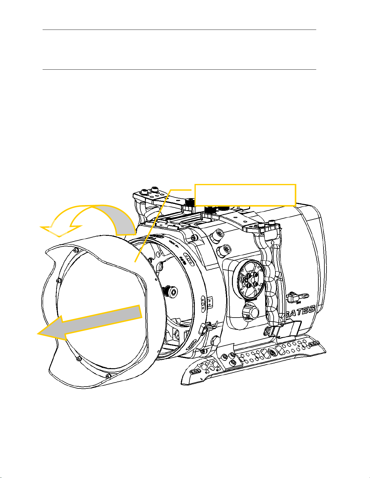
✓Port. Remove the Port by rotating 90 degrees while facing the front of the
housing. Pull the port away from the Port Ring.
TIP: Liberal lubrication of the Port o-ring allows easier rotation during
installation/removal.
1
2
Rotate the port 90 degrees then pull
forward to remove.

ALEXA 35 Housing Setup Page 9
✓Port Rings. Your housing, if upgraded from the Gates MINI Housing, may utilize
conventional Port Rings (vs Stackable Port Rings, found in the next section). To
remove, release the port lock on the lower left side of the housing, and then
rotate 90° CCW and pulling forward.
NOTE: Some lenses do not require a Port Ring.
Release the Port Lock
1
2
3
Rotate the Port Ring 90
degrees counterclockwise
direction, and then gently
pull forward to remove.

ALEXA 35 Housing Setup Page 10
✓Stackable Port Rings SPR’s. New or upgraded ALEXA 35 Housings will have
SPR’s. SPR port locks are on either left or right side of the SPR. Release the
port lock on the side of the SPR, and then rotate 90° CCW and pulling forward.
NOTE: Some lenses do not require an SPR.
Release the Port Lock(S)
1
2
3
Rotate the Port Ring 90
degrees counterclockwise
direction, and then gently
pull forward to remove
each SPR.
ALEXA 35 Housing Setup Page 11
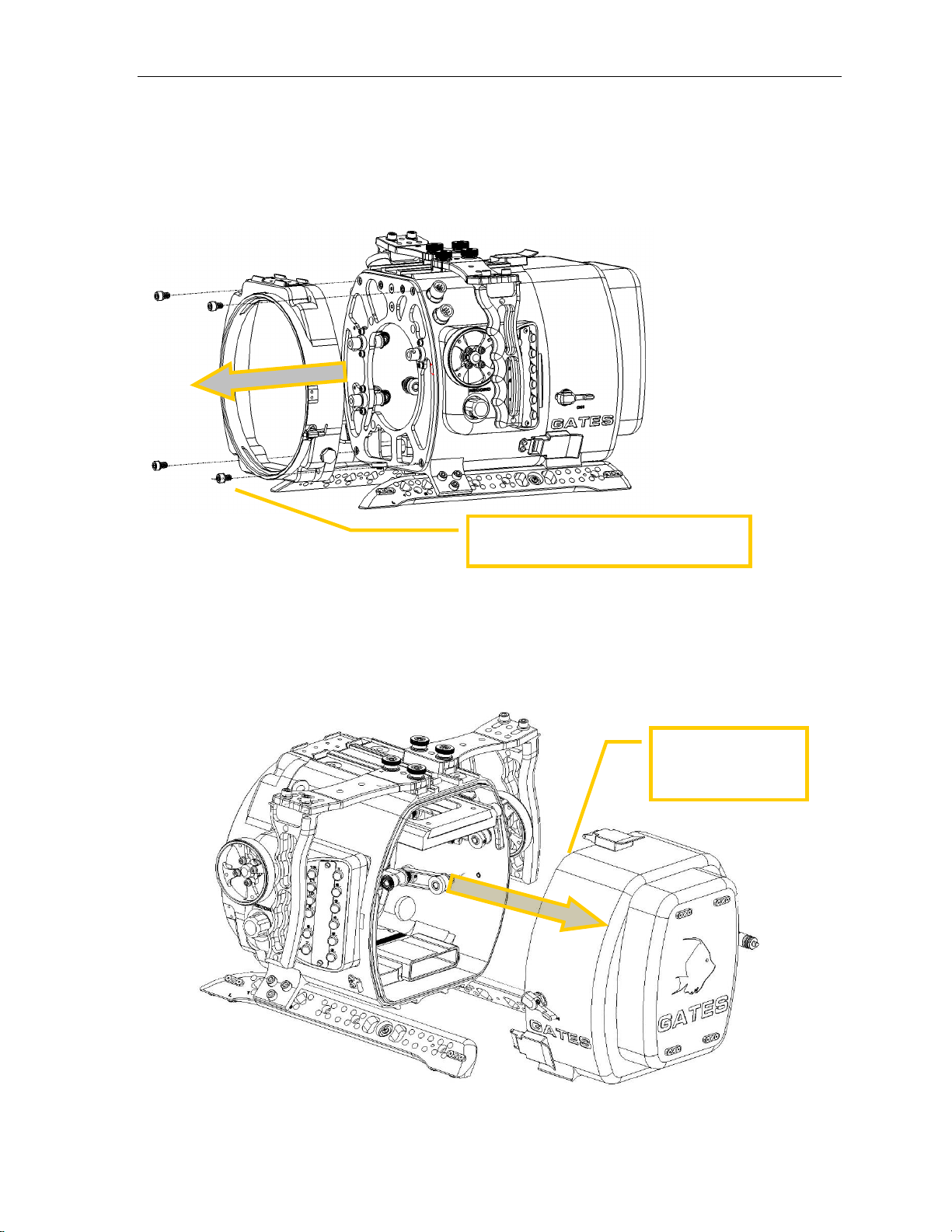
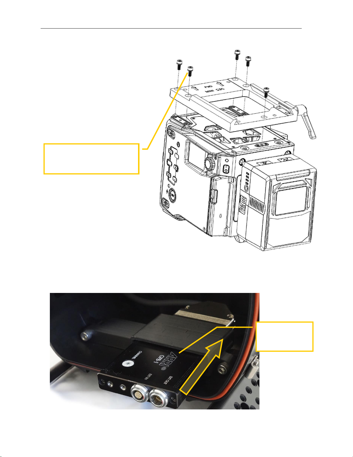
✓Port Base. Remove 4 screws/washers, then the Port Base.
✓Rear Shell removal. Release three (3) latches by depressing the lock and pulling
up on the latch. Once released the rear shell will remove freely.
Remove 4 screws and washers, then the
Port Base.
Slide the rear shell
back until it's free
from the housing.

ALEXA 35 Housing Setup Page 12
✓Camera Dovetail Mount Removal. Rotate the lever lock until the Camera Mount
is loose. The lock lever is a ratcheting type: pull out to place in a new position to
continue loosening. Slide the camera mount to the rear and free of the housing.
Rotate Level Lock counter-
clockwise to release the
camera mount dovetail. Then
slide the camera mount rear
and free of the housing.
1
2

ALEXA 35 Housing Setup Page 13
ALEXA 35 Camera Preparation
✓Camera Basics. Strip down the ALEXA 35 to the bare camera body. Remove
the following items:
✓Antenna
✓Camera Lens
✓Any additional mounts or brackets
The only items remaining are camera, B-mount adapter, and battery (CORE-SWX
HELIX shown).
GPB-1 Module Preparation
✓Remove the GPB-1 Module's threaded standoffs and replace with the supplied 4-
40 x 5/16" pan head screws as shown below. This will allow the module to be
properly seated in the housing carrier.
Remove the standoffs.
Replace with supplied
4-40 x 5/16" pan
head screws.
ALEXA 35

ALEXA 35 Housing Setup Page 14
GPIO Assignable Setup
✓The ALEXA 35 Housing has 12 assignable GPIO buttons located on the side of
the housing. Use your Arri Viewfinder to assign the desired function to each
button. Please refer to your ARRI Mini camera manual for a list of assignable
functions.
The Pushbutton Plate
is marked with 1-12 to
show where each
button is assigned in
the camera's menu.
The housing has GPIO 7-12
marked with the following
camera functions: FN, Camera
1-3, Peaking and Auto White
Balance.
The white marker plate can be
marked by the user to indicate
the assigned function for GPIO
1-6.
ALEXA 35 Housing Setup Page 15
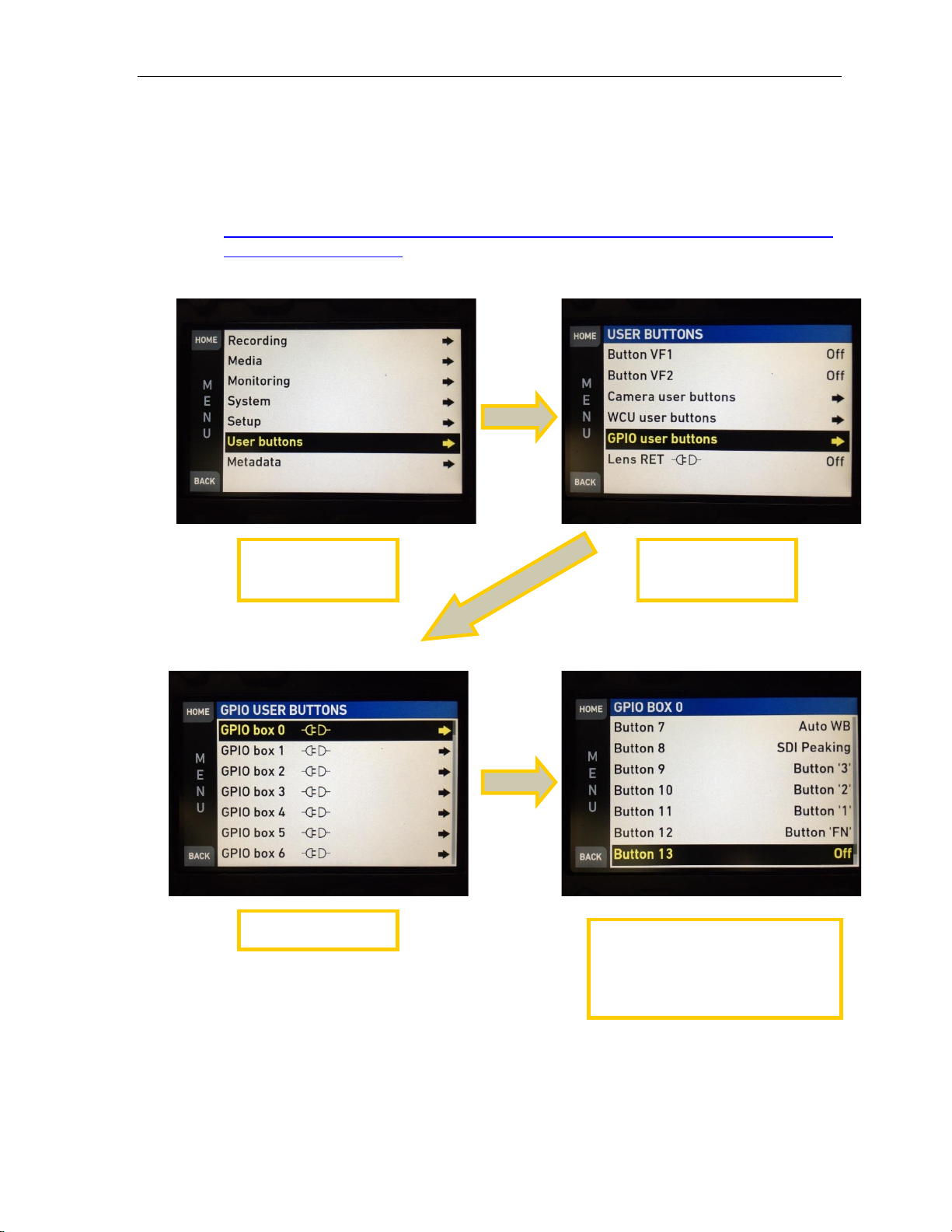
✓Use the ALEXA 35 side panel or viewfinder to configure the camera's assignable
buttons. The pictures bellow illustrate how to setup the user assignable functions.
A full list of assignable functions is found on the Gates website:
https://www.gateshousings.com/wp-content/uploads/2015/10/ARRI-ALEXA-Mini-
GPIO-Functions-R2.pdf
Enter Menu and
select User buttons.
Select GPIO user
buttons.
Select GPIO box 0.
Configure assignable 1-6 as
desired. Assignable 7-12 should be
setup as shown above to match
functions pre-marked on the
housing.
ALEXA 35 Housing Setup Page 16
Camera Installation
✓Camera Bridgeplate Installation.
Mount the ALEXA 35 camera
to the Bridgeplate Adapter with
the four supplied screws.
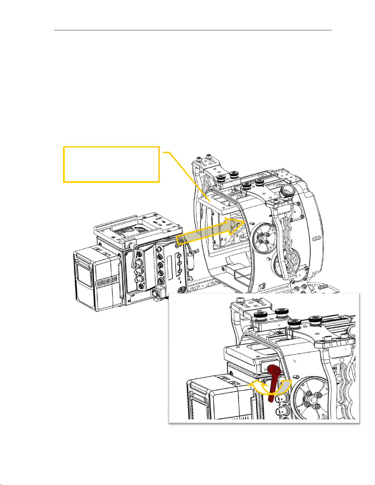
✓Install GPIO box. Slide the GBP-1 GPIO box into the housing cradle as shown
below. Install the GBP-1 with the Arri logo face up so the connectors can mate
properly.
Install 4 screws to secure the mount
to the camera.
Note: ALEXA Mini Camera shown
Slide the GPIO box
into housing cradle
with Arri Logo facing
up.
ALEXA 35 Housing Setup Page 17
✓Insert the Monitor Cable into the housing. Refer to the Monitor Mount / Video
Connections section of this manual for details.
✓Insert Camera into housing. Gently slide the camera fully forward on the housing
dovetail. The camera should move into the housing without obstruction.
CAUTION: AVOID OBSTRUCTIONS. The camera should insert freely without
obstruction. Stop If an obstruction or resistance is encountered. Remove the
camera and find the obstruction before trying again.
✓Lock the camera into
position with the
ratcheting locking
lever.
The Camera Mount will slide onto
the dovetail here. Stop inserting
the camera if you encounter
obstructions.
ALEXA 35 Housing Setup Page 18
Cable Connections
Prior to closing the housing shell, the following cable connections must be made:
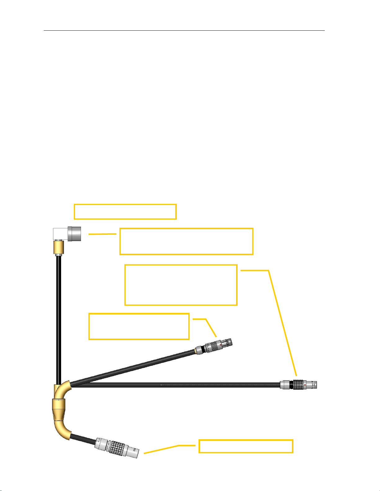
✓GPIO / Record. The 4-way GPIO cable connects the GPIO box to the ALEXA 35
camera. It also connects to the housing's run stop switch. See cable diagram
below for details.
✓External Monitor. At this stage, connect the External Monitor BNC connector to
SDI 1 port on ALEXA 35 camera. Also mate the External Monitor power to the
battery D-Tap (or P-Tap) with supplied D-Tap adapter.
✓Surface SDI. Optionally connect surface SDI cable to SDI 2 port on ALEXA 35
camera.
✓Other. Optionally you may have other cable connections for surface camera
control, lens control, etc. These are special circumstances, contact Gates for
details.
LBUS. Mate this connector with the
LBUS port on ALEXA 35 camera,
located on the camera front, right side.
NOTE: It may be necessary to slide out
the camera slightly to access this port.
GPIO. Mate with GPIO box OUT.
Run / Stop. Mate this connector
with RS port on ALEXA 35 camera,
located on camera rear.
Record Trigger. This BNC-type connector will
mate with the record trigger connector on the
housing. Upper right, inside shell.
GPIO / Record 4-way
Cable

ALEXA 35 Housing Setup Page 19
Lens Gear Drives (LGD’s)
✓General Notes. This section
addresses the installation of three
LGD’s – 1 x CCW (Counter Clock
Wise) and 2 x CW (Clock Wise).
These designators are applied
because two LGD’s point in a CW
direction and the other in a CCW
direction, The LGD’s are marked
CCW and CW.
You will install guide bars and drive
shafts that match the lens of your
choice. Information on which
guide bars, drive shafts and port
rings to use for your lens is
available on the support page at
http://www.gateshousings.com/.
✓Secure Guide Bars. Insert the guide bars by threading them into the front
bulkhead. Tighten firmly by hand –no tools are required but wrench flats are
provided on the guide bars should this be necessary.
✓Install Drive Shafts. These are ¼” black delrin and have a flat spot milled into
one end. This end inserts into the drive coupler at the face of the front bulkhead.
Secure gently with the set screw on the coupler. Do not overtighten.
✓LGD’s mounting. Install the LGD’s in their proper orientation with pivot gear
screws facing forward. Slide it onto the guide bar and drive shaft, then line up
the LGD with the lens gear you wish it to access.
The ALEXA 35 includes three
LGD’s – 2x CCW and 1x CW.
Insert the drive shaft into the
coupler. One end of the shaft
will have a small flat spot.
Align this with the set screw,
and tighten gently. Do not
over tighten.
Note: Different Gates housing shown.
Thread the Guide Bar into the
front shell and tighten by
hand.
ALEXA 35 Housing Setup Page 20
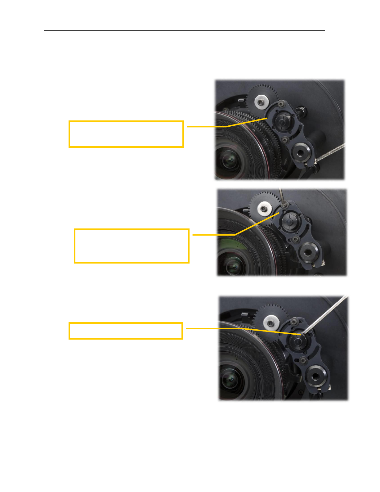
The sequence of tightening screws on the LGD’s is important.
✓Step 1. Tighten the LGD mount screw
securing it to the guide bar. Critical: the
drive shaft/gear hub must be centered
with the opening on the bracket.
✓Step 2. Pivot the larger gear onto the lens
gear such that it makes intimate contact.
Carefully observe that the gear is still
properly aligned and the drive shaft/gear
hub is centered with the LGD bracket (see
photo). Tighten the two pivot screws
gently to secure it in position.
✓Step 3. Firmly tighten the screw that
couples the drive gear hub to the drive
shaft.
TIP. The gear hub / drive shaft coupling acts
like a clutch –the drive shaft will ‘slip’ when
reaching the end of travel in either direction.
Tightening the screw more will allow less slip.
Adjust this amount of slip at your discretion.
✓Set the focus/iris indicators. The left and right side Gear Controls have silicone
bands. The white silicone can be marked to indicate focus / iris position.
Center the drive shaft/gear hub to the
bracket. Tighten the screw and secure
the LGD to the guide bar.
With the drive shaft/hub centered, pivot
the larger gear to make intimate contact
with the lens gear. Gently tighten 2 pivot
screws.
Couple to Drive Shaft .
Table of contents
Other Gates Camera Accessories manuals

Gates
Gates CX700 User manual

Gates
Gates EX1R User manual

Gates
Gates Pro Action User manual

Gates
Gates AVCCAM AG-3DA1 Guide

Gates
Gates AX100 User manual

Gates
Gates Z100 User manual

Gates
Gates C300 User manual

Gates
Gates POVCAM AG-HCK10G Guide

Gates
Gates F55 User manual

Gates
Gates DEEP WEAPON Upgrade User manual


