Gates F55 User manual
F55 Underwater Housing
Setup, Use, and Care Guide

Cautions Page 2
Copyright 2013, Gates Underwater Products, Inc.
Last document revision: 7-1-2013
Photos by Lee Peterson / Marine Camera Distributors and
John Ellerbrock / Gates Underwater Products
This manual and current revision is available in 8.5 x 11 size and full color at
http://www.gateshousings.com/documentation.html
Gates Underwater Products, Inc.
13685 Stowe Drive
Poway, California 92064 USA
Phone: 800.875.1052 toll-free in the U.S.
858.391.0052 outside the U.S.
Fax: 858.391.0053
Web: GatesHousings.com

Cautions Page 3
Table of Contents
Setup, Use, and Care Guide.............................................. 1
Introducing the F55 Underwater Housing .......................... 4
Features............................................................................. 4
Warranty Disclaimer .......................................................... 4
Unpacking F55................................................................... 5
1:Cautions............................................................................. 6
2:F55 Setup .......................................................................... 7
F55 Housing Configuration / R5 Recorder......................... 7
F55 Housing Preparation................................................... 8
Sony F5 & F55 Camera Preparation ............................... 12
Camera Installation.......................................................... 13
Lens Mount Adapters....................................................... 16
Lens Gear Drives (LGD’s) ............................................... 18
Water Alarm (Optional) .................................................... 21
Check Operation.............................................................. 22
Front Shell, Port and Port Ring........................................ 23
Monitor Mount / Video Connections................................. 26
Housing Closure .............................................................. 29
Adjustable Handle Grips .................................................. 31
Seal Check ...................................................................... 32
Final Checks .................................................................... 32
3:F55 Operation.................................................................. 33
Right Side Controls.......................................................... 33
Left Side Controls ............................................................ 34
Buoyancy Adjustment ...................................................... 35
Accessories ..................................................................... 37
Port Options..................................................................... 42
Bracket Mount Locations ................................................. 44
Lighting Systems ............................................................. 45
Controlling Reflections..................................................... 45
Travel / Transport ............................................................ 46
4:F55 Maintenance ............................................................. 47
Housing Care and Maintenance ...................................... 47
O-Ring Care and Maintenance ........................................ 48
5:Customer Support............................................................ 49

Cautions Page 4
Introducing the F55 Underwater Housing
Congratulations on owning a new Gates product: the F55 housing. You’ve selected an
underwater imaging tool that will provide years of value and reliable service. We
designed the F55 specifically for the Sony F5 and F55 digital cinema cameras.
Please read through this entire guide to learn about the F55 so you can get the most out
of this imaging tool. In this section, we’ll introduce you to the features of the F55 so you
can get started.
Features
F55 has several key features:
Lens flexibility. The F55 can accommodate a variety of different PL mount and
Nikon DSLR lenses with no change to control locations. Focus, Iris, Zoom remain
in the same location regardless of optics used.
Full camera control. All practical controls are accessed directly with the F55
housing, as is the full menu system of the camera.
Cinema-grade design. Lens choice and control access are just two of the many
features designed into the F55. A/R coated glass optics, optional HD-SDI surface
feed, and Seal Check are a few of the items any professional will appreciate.
Warranty Disclaimer
The F55 underwater housing is a tool that, like any tool, requires knowledge and
understanding to be effective.
Your responsibility is to learn the proper setup, use and care of the F55. Because we
can only provide you with the information necessary to do so, Gates does not warrant
the contents of your housing (e.g. your camera and lenses) under any circumstance.
We warrant the F55 as an image acquisition tool for a period of 2 years. The Seal
Check unit is warranted for 1 year. Optics (Dome and Flat ports) are warranted for a
period of 1 year or 100 hours salt water contact, whichever comes first.
Gates does not warrant optical performance or image quality.
If you have any questions about the setup, use and care of the F55, contact Gates
directly. Details are in section 5.

Cautions Page 5
Unpacking F55
After you remove the F55 from its shipping container, carefully inspect it for missing
parts or damage that may have occurred during shipment. If you discover any
discrepancies, contact Gates or your dealer immediately for assistance.
Standard Parts
F55 Housing.
Camera Bridgeplate and Mount.
Lens Gear Drives (1x Clockwise
and 2x Counter Clockwise).
Guide Bars and drive shafts for
your lens of choice.
Hard Sided Rolling Case(s).
Seal Check system.
Tool Kit with case.
Various assembly and spare
parts for the F55 including
bolts, set screws and o-rings.
Spare O-Ring Kit.
Carry Handle.
Trim Weights (quantity
dependent on configuration).
Port(s) of choice (Dome, either
glass or acrylic, or Flat) and
shade.
Focus / Iris Marker Rings.
EM50 External Color Monitor.
ND Filter Lockout
HDMI Adapter Cable.
Optional Parts
Microphone or Hydrophone.
Water alarm.
HD-SDI surface feed bulkhead connector and cable.
Light System.
Tripod Adapters / Mounts.
Port Ring(s) of choice for your lens (as needed).
Focus / Iris / Zoom Gears for your choice of lens (applicable to DSLR lenses
only. Refer to Gates Lens Compatibility Chart for more information).

Cautions Page 6
1: Cautions
TRANSPORT. NEVER ship or transport your F55 or F5 camera inside the F55
housing. The housing was not designed for this purpose and severe damage
may result.
USER RESPONSIBILITY. This Setup, Use and Care guide contains important
detailed procedures for setup and use of the F55. It is the user’s responsibility to
read, understand and employ these procedures. Failure to do so can result in
poor or non-operation of the F55 and may void your warranty.
Contact Gates if you have questions this manual or using the F55.

F55 Setup Page 7
2: F55 Setup
The F55 requires complete and thorough setup prior to use.
F55 Housing Configuration / R5 Recorder
The F55 comes in two configuations: one when used without the R5 recorder, and one
when used with. The difference is only in the depth of the Rear Shell, as shown in the
photos.
Rear Shell for use without
the Sony R5 Recorder.
Extended Rear Shell for use
with the Sony R5 Recorder.

F55 Setup Page 8
F55 Housing Preparation
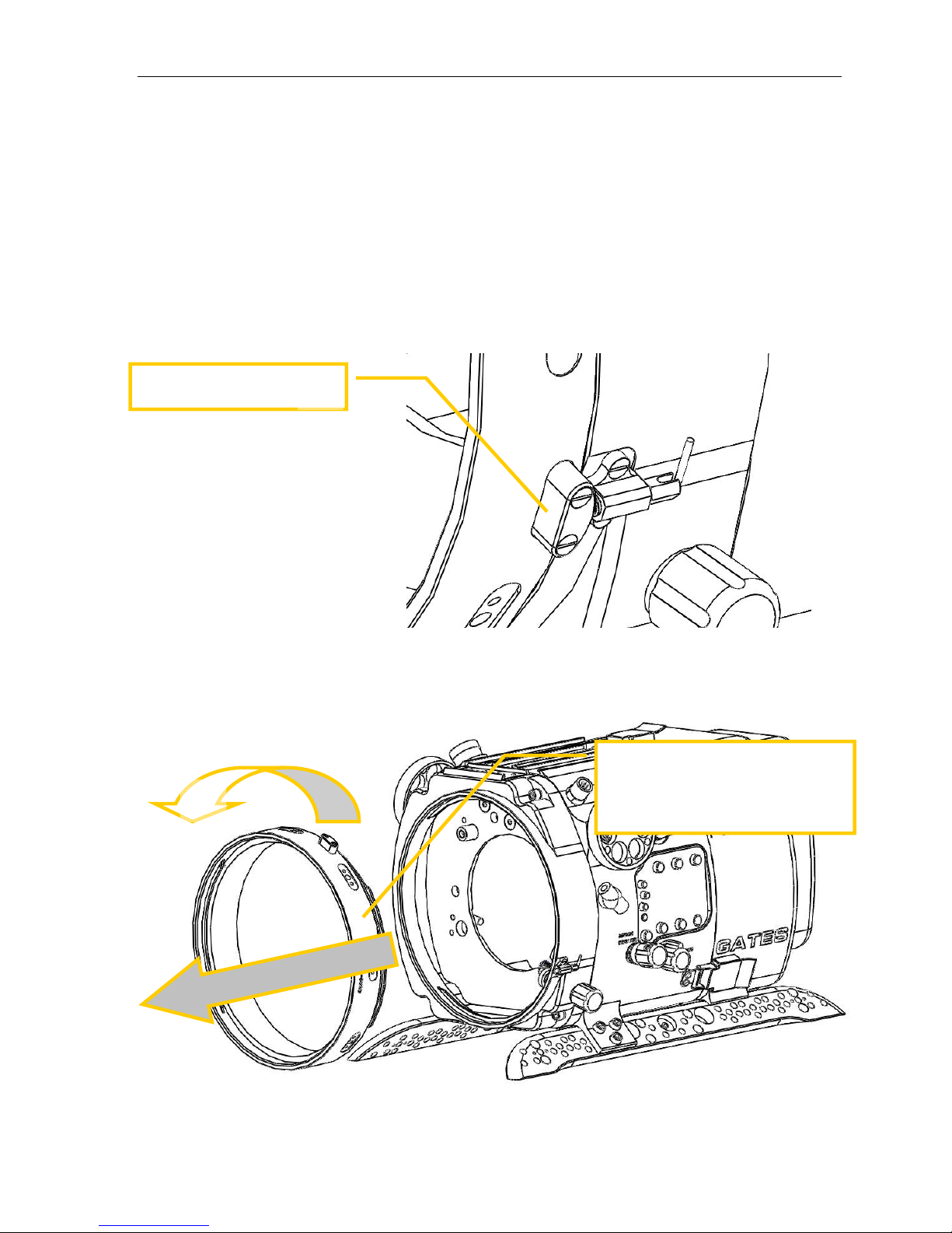
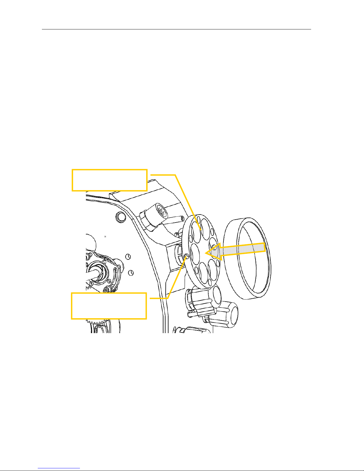
Port. Remove the Port by rotating 90 degrees Counter Clock Wise (CCW) direction
while facing the front of the housing. Gently pull the Port away from the Port Ring
or Front Bulkhead.
TIP: Liberal lubrication of the Port o-ring allows easy rotation during
installation/removal.
N=
O=
Rotate the port 90 degrees
counterclockwise direction, then
gently pull forward to remove.
F55 Setup Page 9
Port Lock. Release the Port Lock on the lower left side of the housing.
Port Ring. Remove the Port Ring by rotating 90° CCW and pulling forward.
NOTE: Some lenses do not require a Port Ring.
O=
P=
Rotate the Port Ring 90 degrees
counterclockwise direction, and then
gently pull forward to remove.
Release the Port Lock N=
F55 Setup Page 10
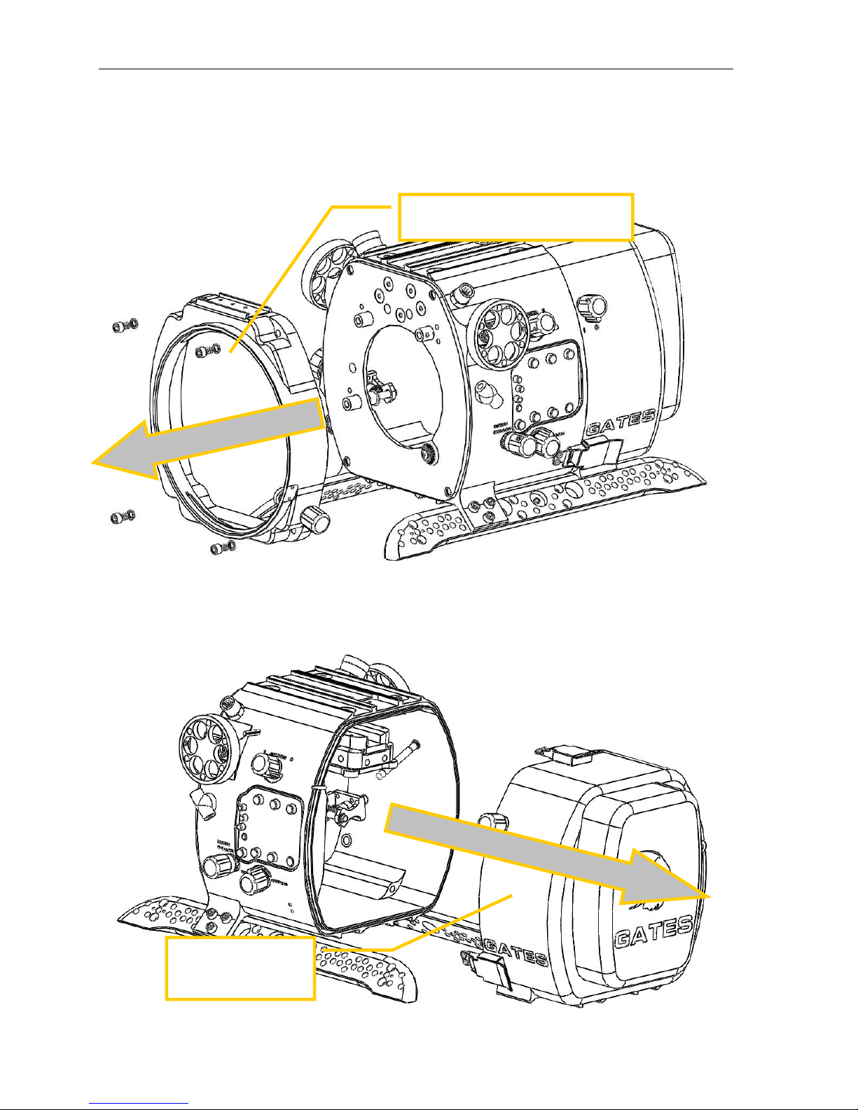
Front Shell. Remove 4 screws, then the Front Shell.
Rear Shell removal. Release three (3) latches by depressing the lock and pulling
up on the latch. Once released the rear shell will remove freely.
Slide the rear shell
back until free from
the housing.
Remove 4 screws and washers, then
the Front Shell.
F55 Setup Page 11
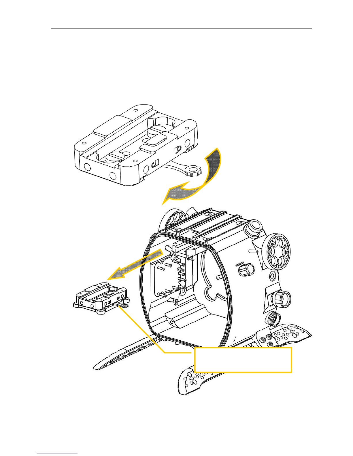
Camera Bridgeplate Removal. Release the lever lock on the right and slide the
camera mount to the rear and free of the housing.
Release the camera Bridgeplate with
this lever. Slide rearward out of the
housing.
N
O=
F55 Setup Page 12
Sony F5 & F55 Camera Preparation
Camera Basics Strip down the F5/F55 cameras to the bare camera body.
Remove the following items:
Entire LCD Monitor unit
Top Hand Grip Unit
Tape measure hooks
Bottom Shoulder Rest
Remove any Camera Lens
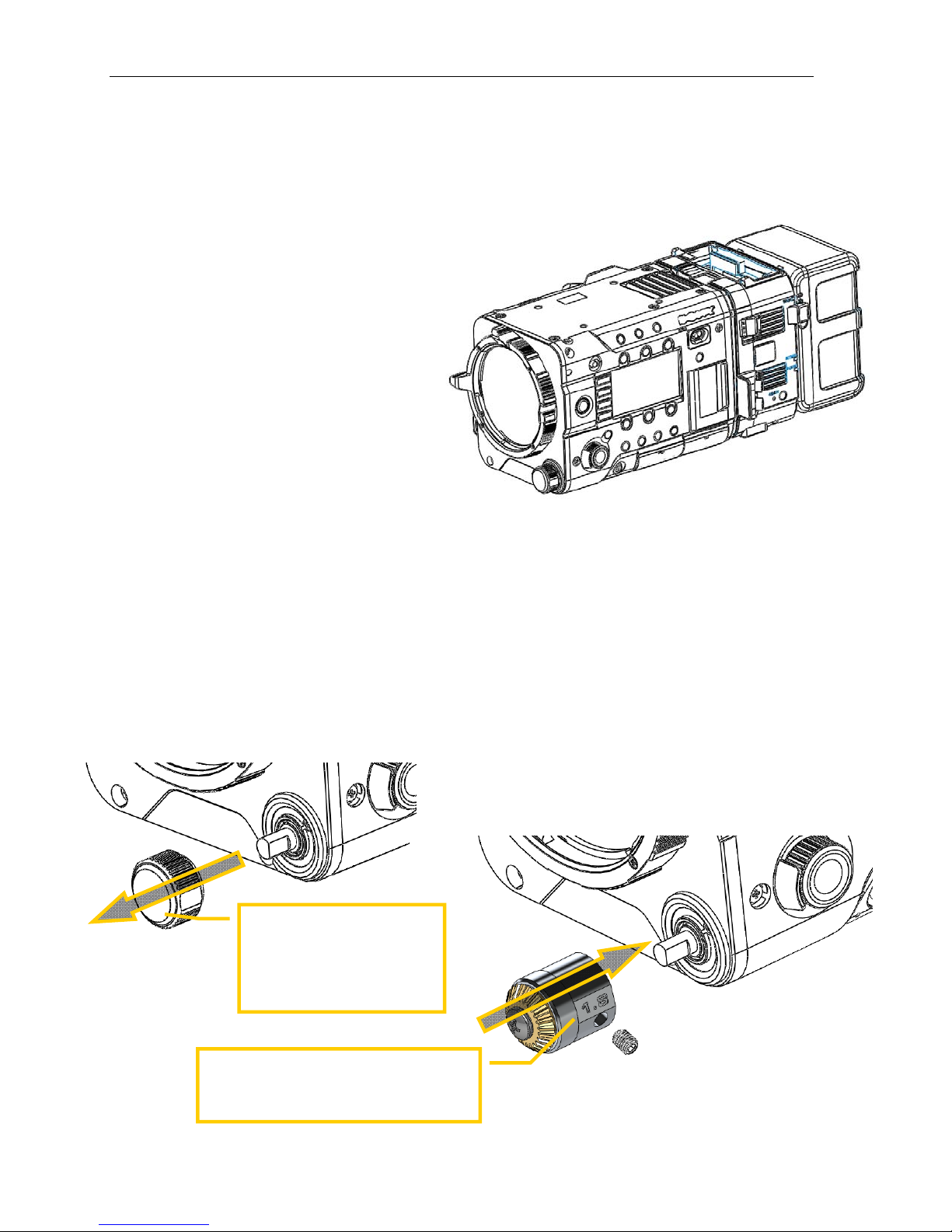
ND Filter Knob. The ND Filter Knob on the F55 camera must be removed, and
replaced with a special version by Gates. This is necessary to allow control of ND
filter with the F55 Housing.
First, rotate the ND filter knob to the CLEAR POSITION. Then remove the
ND filter knob from the camera by gently pulling it away. It will expose a shaft
with a flat on one side.
Next, install the Gates ND Filter Knob with the set screw on the same side as
the flat on the control shaft. PRESS AND HOLD the Gates ND Filter Knob
onto the camera while tightening the set screw.
Install the Gates ND Filter Knob. PRESS
AND HOLD the knob against the camera
while tightening the set screw.
Rotate the ND Filter Knob to
the CLEAR position. Then
gently pull the ND Filter knob
from the camera and expose
the shaft with a flat on one
side.
F55 Setup Page 13
Camera Installation
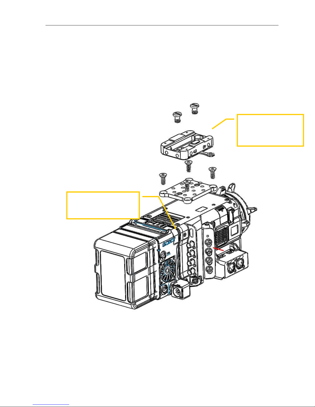
Camera Bridgeplate Installation. The F5/F55 camera is mounted first to a
Bridgeplate Adapter with four screws, then to the Bridgeplate with two
thumbscrews, as shown.
Remove all items from the F5 /
F55 camera except battery, R5
recorder (optional), and
recording media.
Mate the Camera to the
Bridgeplate adapter as
shown, then secure the
Bridgeplate with two
thumbscrews.

F55 Setup Page 14
Pull out controls on left side of Front Shell. Housing controls on the front shell
must be retracted for camera clearance during insertion. Assign, Menu and Option
controls will retract. Refer to Section 3 Operation for more details on the housing
controls.
Interior Trim Weights-- Required. Mount two 8oz weights to the interior of the
shell as shown below. These two trim weights are required to balance the housing
left / right.
Refer to the ‘Buoyancy Adjustment’ section below for more details.
Place camera to housing. Locate the Bridgeplate and the Dovetail receiver.
Insert Camera into housing. Gently slide the camera on the Tray into the housing
until fully seated. The camera should move into the housing without obstruction.
CAUTION: AVOID OBSTRUCTIONS. The camera should insert freely, without
obstruction. If obstructions or resistance are encountered, stop. Remove the
camera, find the cause of the obstruction, and try again.
Lock the camera into position with the locking lever.
Mate and Check Controls. This is a good time to verify operation of all Mid Shell
controls. Push in Assign, Menu and Option controls on the left side, confirming that
the control touches and operates the associated camera function (see Section 3
Controls for more information). Check all pushbuttons, too.
Two 8 oz trim weight are
required, and mounted here to
balance the housing left and
right.
Pull out the Assign, Menu and
Option Controls.

F55 Setup Page 15
Push in and Check controls.
The Bridgeplate will slide
onto the dovetail here.
Slide carefully. Stop if you
encounter obstructions.
N
O=
P=

F55 Setup Page 16
Lens Mount Adapters
If you are using a Sony FZ mount lens then no mount adapter is required. Continue to
the next section.
A mount adapter is required to use PL and Nikon DSLR lenses.
FZ to PL Mount Adapter. To use PL mount lenses, install the Sony FZ to PL
adapter.
FZ to Nikon Mount Adapter. Nikon DSLR lenses will require 2 mount adapter
parts:
MTF Services Adapter (MTF FZ to Nikon Adapter). This Third party adapter
can be acquired directly from MTF Services
Gates Iris Gear Adapter. This adapter is available from Gates. It provides a
gear interface between the MTF services adapter and the F55 Housing.
Install the Sony FZ Mount
adapter if you are using PL
mount lenses.
Install the MTF FZ to Nikon adapter (blue) to the
F5/F55 camera first. Then install the Gates Iris Gear
Adapter (green) to the MTF mount in the approximate
position shown. A single screw on the bottom of the
Gear Adapter will secure it to the MTF adapter.

F55 Setup Page 17
Gear Rings When using a DSLR lens, a gear ring is required to slip over the focus
or zoom rings on the lens, which in turn interface with the F55 Housing. Gear Rings
are very specific to a given lens. Contact Gates for details on the appropriate Gear
Rings for a specific DSLR lens.
Mount lens to the camera. At this time, mount your lens of choice to the F5/F55
camera.
Install Gear Rings onto your
DSLR lens.
Mount lens to the F5/F55
Camera.
F55 Setup Page 18
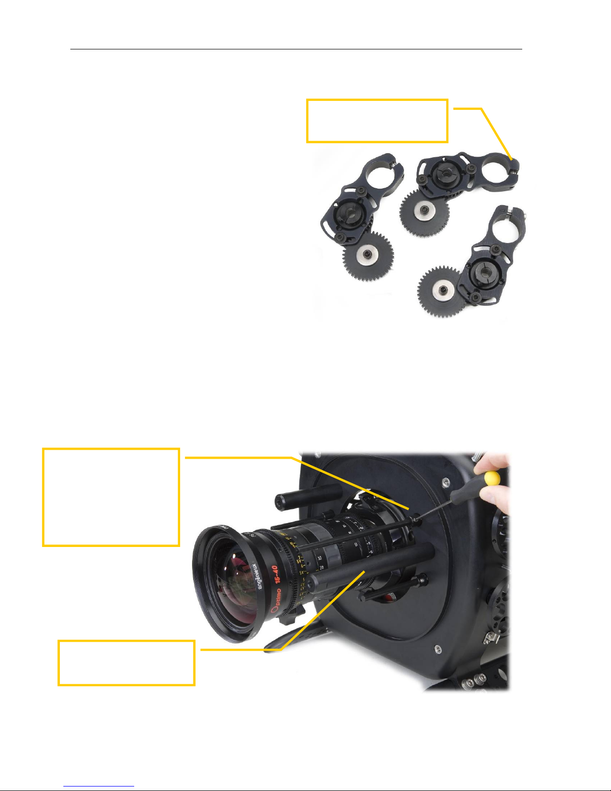
Lens Gear Drives (LGD’s)
General Notes. This section
addresses the installation of three LGD’s –
2 x CCW (Counter Clock Wise) and 1 x
CW (Clock Wise). These designators
are applied because two LGD’s point
in a CCW direction and the other in a
CW direction, The LGD’s are marked
CCW and CW.
You will install guide bars and drive
shafts that match the lens of your choice.
A lens cross reference is included in your
F55 documentation package and is updated on
a regular basis. Visit GatesHousings.com or
contact Gates for a current cross reference.
Secure Guide Bars. Insert the guide bars by threading them into the front
bulkhead. Tighten firmly by hand – no tools are required but wrench flats are
provided on the guide bars should this be necessary.
Install Drive Shafts. These are ¼” black delrin and have a flat spot milled into one
end. This end inserts into the drive coupler at the face of the front bulkhead.
Secure gently with the set screw on the coupler. Do not overtighten.
The F55 includes three LGD’s
– 1x CCW and 2x CW.
Insert the drive shaft into the
coupler. One end of the shaft
will have a small flat spot.
Align this with the set screw,
and tighten gently. Do not
overtighten.
Note: Different Gates housing shown.
Thread the Guide Bar into the
front shell and tighten by
hand.

F55 Setup Page 19
LGD’s mounting. Install the LGD’s in their proper orientation with pivot gear
screws facing forward. Slide it onto the guide bar and drive shaft, then line up the
LGD with the lens gear you wish it to access.
The sequence of tightening screws on the LGD’s is important.
Step 1. Tighten the LGD mount screw
securing it to the guide bar. Critical: the
drive shaft/gear hub must be centered with
the opening on the bracket.
Step 2. Pivot the larger gear onto the lens
gear such that it makes intimate contact.
Carefully observe that the gear is still
properly aligned and the drive shaft/gear hub
is centered with the LGD bracket (see photo).
Tighten the two pivot screws gently to secure
it in position.
Step 3. Firmly tighten the screw that couples
the drive gear hub to the drive shaft.
TIP. The gear hub / drive shaft coupling acts
like a clutch – the drive shaft will ‘slip’ when
reaching the end of travel in either direction.
Tightening the screw more will allow less slip.
Adjust this amount of slip at your discretion.
Center the drive shaft/gear hub to the
bracket. Tighten the screw and secure
the LGD to the guide bar.
With the drive shaft/hub centered, pivot
the larger gear to make intimate contact
with the lens gear. Gently tighten 2 pivot
screws.
Couple to Drive Shaft .
F55 Setup Page 20
Set the focus/iris indicators. The left and right side Gear Controls have indicator
rings. These shipped in the parts kit. These are white plastic for marking focus / iris
indications.
Secure the ring with the two set screws in the knob as shown.
Verify Operation. Once positioned and secured check operation of the Focus and
Iris controls. They should rotate freely – but with slight resistance – in both
directions and through the entire range of travel. If not, repeat steps 1-3.
In a subsequent section “Check Operation” you will power on the camera and verify
the Zoom control is also smooth and operational.
Slip the white ring over the
Gear Control knob.
Secure with set screws
here and opposite on the
knob.
Table of contents
Other Gates Camera Accessories manuals


