manuals.online logo
Brands
  1. Home
  2. •
  3. Brands
  4. •
  5. Leviton
  6. •
  7. Control Unit
  8. •
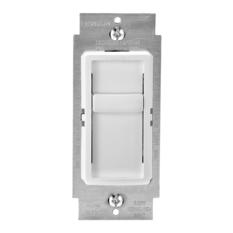
  9. Leviton Decora Illumatech User manual

Leviton Decora Illumatech User manual

Single Pole (One location) or
3-Way (Multi-location)
120VAC, 60Hz
Quiet Fan Speed Control
Cat. No. IPF01-1L, 1.5A (Lighted)
INSTALLATION INSTRUCTIONS
FEATURES
• Leviton's Decora® style design • Color conversion available
• Large ON/OFF switch • ON/OFF LED indicates status of load
INSTALLATION INSTRUCTIONS
WARNING: TO BE INSTALLED AND/OR USED INACCORDANCE WITH APPROPRIATE ELECTRICAL CODES
AND REGULATIONS.
WARNING: IF YOU ARE NOT SURE ABOUT ANY PART OF THESE INSTRUCTIONS, CONSULTA QUALIFIED
ELECTRICIAN.
WARNING: TO AVOID OVERHEATING AND POSSIBLE DAMAGE TO THIS DEVICE AND OTHER EQUIPMENT,
DO NOT INSTALL TO CONTROLARECEPTACLE, FLUORESCENT LIGHTING, A MOTOR- OR A
TRANSFORMER-OPERATED APPLIANCE OTHER THAN APPROPRIATE CEILING FANS.
WARNING: TO REDUCE THE RISK OF FIRE OR ELECTRICAL SHOCK, THIS CONTROL IS TO BE USED
WITH CEILING FANS THAT ARE MARKED AS SUITABLE FOR USE WITH A SOLID-STATE FAN SPEED
CONTROLAND IS RATED 120 VOLTS AC, TOTAL LOAD 1.5 AMPERES MAXIMUM.
WARNING: FOR USE ON CEILING PADDLE FANS WITH SPLIT-CAPACITOR OR SHADED POLE MOTORS
ONLY. PLEASE REFER TO FAN MANUFACTURER’S INSTRUCTIONS OR RATING LABEL ON THE MOTOR TO
CONFIRM TYPE. USE WITH ANY OTHER TYPES OF MOTORS OR EQUIPMENT MAY CAUSE OVERHEATING
AND/OR DAMAGE TO THE MOTORS OR EQUIPMENT.
OTHER CAUTIONS:
1. USE ONLY ONE (1) SPEED CONTROL PER LOAD. THE SWITCH(ES) WILL TURN ON THE FAN AT THE
SPEED LEVEL SELECTED AT THE CONTROL.
2. DISCONNECT POWER WHEN SERVICING FIXTURE.
3. USE THIS DEVICE ONLY WITH COPPER OR COPPER CLAD WIRE. WITHALUMINUM WIRE USE ONLY
DEVICES MARKED CO/ALR OR CU/AL.
MULTI-GANG INSTALLATION:
There is NO derating necessary for multi-gang installations of this Quiet Fan Speed control.
TO INSTALL:
1. WARNING: TO AVOID FIRE, SHOCK, OR DEATH;
TURN OFF POWER AT CIRCUIT BREAKER OR FUSE
AND TEST THAT POWER IS OFF BEFORE WIRING!
2. Remove existing wallplate and switch, if applicable.
3. Remove 3/4¨ (1.9 cm) of insulation from each circuit
conductor. Make sure the ends of wires are straight.
4. Connect wires per appropriate WIRING DIAGRAM as
follows: NOTE: Common terminal of 3-Way Switch is
usually labeled and/or BLACK. Twist strands of each
lead tightly and, with circuit conductors push firmly into
appropriate wire connector. Screw connectors on
clockwise making sure no bare wires show below the wire
connectors. Secure each connector with electrical tape.
NOTE: For single pole applications, cap one BLACK lead
with an appropriate size wire connector. Secure connector
with electrical tape.
5. Installation may now be completed by carefully positioning
all wires to provide room in outlet box for control. Mount
control into box with mounting screws supplied.
6. Restore power at circuit breaker or fuse. Check for proper operation by pressing the ON/OFF push-button
(GREEN LED OFF) to turn ON the Fan Speed Control. Position the slider to each of the three levels: HIGH (top
of stroke), MEDIUM (middle of stroke), and LOW (bottom of stroke) (see Figure 1). Ensure that fan speed
changes accordingly. TURN OFF POWER and attach Decora®wallplate.
7. Restore power at circuit breaker or fuse. INSTALLATION IS COMPLETE.
DI-000-IPF01-00A
LIMITED 2 YEAR WARRANTY AND EXCLUSIONS
Leviton warrants to the original consumer purchaser and not for
the benefit of anyone else that this product at the time of its sale
by Leviton is free of defects in materials and workmanship under
normal and proper use for two years from the purchase date.
Leviton’s only obligation is to correct such defects by repair or
replacement, at its option, if within such two year period the
product is returned prepaid, with proof of purchase date, and a
description of the problem to Leviton Manufacturing Co., Inc.,
Att: Quality Assurance Department, 59-25 Little Neck
Parkway, Little Neck, New York 11362-2591 (In Canada send
to Leviton Mfg. of Canada Ltd., 165 Hymus Blvd., Point Claire,
(Quebec), Canada H9R 1E9). This warranty excludes and there
is disclaimed liability for labor for removal of this product or
reinstallation. This warranty is void if this product is installed
improperly or in an improper environment, overloaded, misused,
opened, abused, or altered in any manner, or is not used under
normal operating conditions or not in accordance with any labels
or instructions. There are no other or implied warranties of any
kind, including merchantability and fitness for a particular purpose,
butifanyimplied warrantyis requiredby theapplicable jurisdiction,
the duration of any such implied warranty, including
merchantability and fitness for a particular purpose, is limited to
two years. Leviton is not liable for incidental, indirect, special, or
consequential damages, including without limitation, damage to,
or loss of use of, any equipment, lost sales or profits or delay or
failure to perform this warranty obligation. The remedies provided
herein are the exclusive remedies under this warranty, whether
based on contract, tort or otherwise.
For Technical Assistance Call:
1-800-824-3005 (U.S.A. Only)
1 800 405-5320 (Canada Only)
www.leviton.com
R
DI-000-IPF01-00A
/
R
C O L L E C T I O N B Y L E V I T O N
Figure 1 - Fan Speed Control Functions
Slider
ON/OFF
LED
ON/OFF
Push-Button
Switch
Mounting Strap
Side Sections
DI-000-IPF01-00A 11/30/00, 1:56 PM1
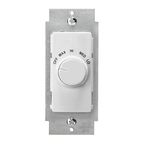
Figure 2 - Color Conversion
Hot (Black)
Neutral (White)
Fan
Fan Speed Control
3-Way Switch
Black
Black
Green
Ground
Green
Ground
Black
White
Red
Line
120VAC, 60Hz
Common
Terminal
(Black Screw)
Hot (Black)
Neutral (White)
Fan
Fan Speed Control
Black
Black
Green
Ground
Black
White
Red
Line
120VAC, 60Hz
Cap with
Wire Connector
Wiring Diagram 1 - Single Location Control Application
COLOR CONVERSION PROCEDURE
The color of this device can be changed to suit your
interior design requirements. Simply obtain a color
conversion kit of the appropriate color from your
Leviton distributor and proceed as follows (please note
that wallplate must be removed).
1. Select the color of the face you desire.
2. The frame has snaps on its sides. Using your
fingers, grip around the Decora®frame and push on
one side to release it from the strap (see Figure 2).
3. Take the new frame and position it properly to the
strap. Position the Slide Switch Shaft with the
opening in the frame and line up the plastic snaps
with the square holes in the strap. Insert the snaps
on one side of the frame into the strap.
4. Firmly press sideways and down to slip the other
snaps into place. The frame snaps in with a audible
click. Ensure that all four snaps are secure.
Replace Decora®wallplate. The color conversion
is complete.
TO OPERATE
•GREEN LED will remain ON when the fan is OFF
- Facilitates access to switch in the dark.
•Depress push-button switch to ON position
- Fan will turn ON (GREEN LED will turn OFF)at
level set by slider.
•Move slider control lever up or down to one of
three levels; HIGH, MEDIUM, or LOW
- Fan will increase or decrease in speed
respectively for desired level.
•Depress push-button switch to OFF position
- fan will turn OFF (GREEN LED will turn ON).
•Fan will turn ON at set speed level (from either
switch location in a 3-way installation).
TROUBLESHOOTING
•Fan does not turn ON and ON/OFF LED does not
turn ON
- Circuit breaker or fuse has tripped.
- Fan has burned out.
- Fan is not connected to line Neutral.
Wiring Diagram 2 - Two Location Control Application
Frame
Strap
Snaps
Push in 2 Locations
ON/OFF
LED
Slider
Wiring Diagram 2 - Three Location Control Application
Hot (Black)
Neutral (White)
Fan
Fan Speed Control
3-Way Switch
Black
Black
Green
Ground
Green
Ground
Black
White
Red
Line
120VAC, 60Hz
Common
Terminal
(Black Screw)
4-Way Switch
Green
Ground
1
1
Travelers between switches "IN"
Travelers between switches "OUT"
2
1
2
2
DI-000-IPF01-00A 11/30/00, 1:56 PM2

Other Leviton Control Unit manuals

Leviton VIZIA RF PLUS VRC0P-1LW User manual

Leviton

Leviton VIZIA RF PLUS VRC0P-1LW User manual

Leviton 59A00-1 User manual

Leviton

Leviton 59A00-1 User manual

Leviton 73A00-4ZB Mounting instructions

Leviton

Leviton 73A00-4ZB Mounting instructions

Leviton Vizia RF+ VRP15-1LW User manual

Leviton

Leviton Vizia RF+ VRP15-1LW User manual

Leviton CP series Operation manual

Leviton

Leviton CP series Operation manual

Leviton 73A00-3ZB Mounting instructions

Leviton

Leviton 73A00-3ZB Mounting instructions

Leviton 47605-C5B User manual

Leviton

Leviton 47605-C5B User manual

Leviton SPLCH User manual

Leviton

Leviton SPLCH User manual

Leviton Quantran QTM00-050 User manual

Leviton

Leviton Quantran QTM00-050 User manual

Leviton 73A00-4ZB Mounting instructions

Leviton

Leviton 73A00-4ZB Mounting instructions

Leviton 72A00-1 Mounting instructions

Leviton

Leviton 72A00-1 Mounting instructions

Leviton 73A00-3ZB Mounting instructions

Leviton

Leviton 73A00-3ZB Mounting instructions

Leviton Decora Illumatech RTF01-10 User manual

Leviton

Leviton Decora Illumatech RTF01-10 User manual

Leviton 47603-ASO User manual

Leviton

Leviton 47603-ASO User manual

Leviton SGAMP User manual

Leviton

Leviton SGAMP User manual

Leviton 95A03-1 Mounting instructions

Leviton

Leviton 95A03-1 Mounting instructions

Leviton Decora Sureslide 6629-3, 1.5A User manual

Leviton

Leviton Decora Sureslide 6629-3, 1.5A User manual

Leviton Opt-X SDX Series User manual

Leviton

Leviton Opt-X SDX Series User manual

Leviton UPB Mounting instructions

Leviton

Leviton UPB Mounting instructions

Leviton N7516 Original operating instructions

Leviton

Leviton N7516 Original operating instructions

Leviton 110A00-1 Mounting instructions

Leviton

Leviton 110A00-1 Mounting instructions

Leviton rMB81-001 Operation manual

Leviton

Leviton rMB81-001 Operation manual

Leviton 10A11-1 Mounting instructions

Leviton

Leviton 10A11-1 Mounting instructions

Leviton 47616-DSB User manual

Leviton

Leviton 47616-DSB User manual

Popular Control Unit manuals by other brands

A.R.I. Eliptix R-30 R 2W Installation, Operating, Maintenance

A.R.I.

A.R.I. Eliptix R-30 R 2W Installation, Operating, Maintenance

Temptek VETERAN VTR Series instruction manual

Temptek

Temptek VETERAN VTR Series instruction manual

ICP DAS USA I-7016D quick start guide

ICP DAS USA

ICP DAS USA I-7016D quick start guide

Carlisle ms 610190-10 Service manual

Carlisle

Carlisle ms 610190-10 Service manual

Rockwell Automation 2711P-RPA installation instructions

Rockwell Automation

Rockwell Automation 2711P-RPA installation instructions

FaderMate Master Control Unit Fittings guide

FaderMate

FaderMate Master Control Unit Fittings guide

Kohler K-10673 Maintenance Guide

Kohler

Kohler K-10673 Maintenance Guide

Lenze 2131 operating instructions

Lenze

Lenze 2131 operating instructions

Xtreme Power Systems XtremeLink Installation and usage manual

Xtreme Power Systems

Xtreme Power Systems XtremeLink Installation and usage manual

DSC Power Series PC5904 installation instructions

DSC

DSC Power Series PC5904 installation instructions

GEM 611 manual

GEM

GEM 611 manual

NSK ASTRO-E 400Z Operation manual

NSK

NSK ASTRO-E 400Z Operation manual

Flowserve Edward 602Y Maintenance manual

Flowserve

Flowserve Edward 602Y Maintenance manual

damixa 48408 Installation instruction

damixa

damixa 48408 Installation instruction

Swegon CCO kit quick start guide

Swegon

Swegon CCO kit quick start guide

Nibe AXC 40 Installer manual

Nibe

Nibe AXC 40 Installer manual

Burkert 5411 operating instructions

Burkert

Burkert 5411 operating instructions

Ebyte E104-BT52 user manual

Ebyte

Ebyte E104-BT52 user manual

manuals.online logo
manuals.online logoBrands
  • About & Mission
  • Contact us
  • Privacy Policy
  • Terms and Conditions

Copyright 2025 Manuals.Online. All Rights Reserved.