Gator GTRAKPRO User guide

GTRAKPRO
Startup Guide
gatortracking.com.au
(Version 2.0)
VEHICLE TRACKING SYSTEM

1 Inclusions
•Main device
•Power cord
•4-pin relay
•Microphone
•SOS cable
1.1 Optional accessories
•5-pin relay*2 (Optional refer Diagram on p7 3.3)
This is a standard automotive relay available from
aftermarket retailers
1.2 Features
•Real-time GPS+AGPS tracking
•Track by time interval/distance/direction change
•Track through SMS or Web
•Remote fuel/power cut-o control via SMS or Server
•Voice monitor
•SOS alarm
•Geo-fence alarm
•Vibration alarm
•Movement alarm
•External power cut-o alarm
•Door status-detection
•Analog & Digital inputs
•Low battery alert
2

1.3 Specifications
2. My device
2.1 Appearance
3
7
1. On/O button
2. SIM card slot (Full size SIM card)
3. Mic
4. SOS botton
5. Extension interface
6. Data
7. Power, Oil/Electricity, ACC
3G 850/900/1900/2100MHz
Frequency QuadBand,Allnetworksupport
WCDMA (3G)
Networks
9-36VDC<300mA
Operating Voltage
Cold Start: <35s
Location Time Hot Start :<2s
<10 meters
Location Accuracy
-20℃~ +70℃
98.5(L) x 52(W) x 15(H) mm
80g
Operating Temperature
Dimension
Weight

2.2 LED indicators
4
Blue GPS LED indicator Green GSM LED indicator
Red Power status
Searching GPS signal0.1s ON & 0.1s OFF
GPS LED Indicator - Blue
GPS is fixed
No GPS fixed or initialising
Steady on
OFF
GSM initialising
0.1s ON & 0.1s OFF
GSM LED Indicator - Green
Receiving GSM signal
As above + connected to APN
0.1s ON & 1.9s OFF
Steady on
No GSM signal or SIM error
OFF
0.1s ON & 0.1s OFF
Power Status - Red
2s ON & 2s OFF
0.1s ON & 1.9s OFF
Steady on
Low battery
Full charged
Normal operating
Device is charging
Low battery/Power off
OFF
Device is in defense statusFlash in a loop

5
3. Installation
3.1 Installing the SIM card
The SIM card should be inserted in the correct
orientation. Note the diagram on the rubber cover
indicating the side the SIM cards notch should face.
Full size SIM card is required but not supplied.
Open the cover
Insert SIM card
with gold ngers
facing up
Power on/off SIM card slot
Turn the battery
switch to the on
position after it
is wired to the
vehicle. Make
sure the device
is turned o
before installing
or removing the
SIM card
(TOP)

6
3.2 Device Wiring Definition
Line
Picture 1
ColourDefinition
1
2
3
4
Red
Black
Orange
Yellow
PW+
GND
ACC
RELAY
12V/24V car battery positive
12V/24V car battery negative
ACC ignition
Relay control
5
6
7
8
Red
Blue
Green
Black
5V-OUT
RX
TX
GND
External power supply
Data RX / backup interface
Data TX /backup interface
Data Ground Output
9Purple ADC
10
11
Orange
Yellow
In1
OUT1
Extended Features
12 Black GND
13 Orange SOS+ SOS button
14 Brown MIC+
15 Black MIC- Microphone
Table 1
Description

7
3.3 Device Wiring Diagram
MIC
Microphone
SOS
Extended
Features
Data
Power
Oil/electricity
ACC
Relay
Notice: The purple line (ADC) of terminal connects to
analog signals line, like analog temperature sensor or
fuel sensor. Voltage detected by analog signal ranges
from 0~30 Vdc.
Oil/Fuel pump
Ignit ion key
Connection
Existing wire from
use box to be cut

3.3 Device Wiring Diagram Cont...
8
Battery
/
Output control Connection
Analog signal
Diagram 1
Negative trigger
connection car type
Positive trigger
connection
car type
Door negative
trigger connection
Door light
Door positive
trigger connection
Door light
Diagram 2
Diagram 3
Relay 1
Relay 2
Car le ft signal wir e
Left turn light
Car right signal wire
Right turn light
Connect to turn light
Car
horn
button
Relay 1
Relay 2
Car horn relay
Car left signal wire
Car right signal wire
Connect to car horn
and turn light
Door switch
Door switch
Left turn light
Right turn light

3.4 Wiring Instruction
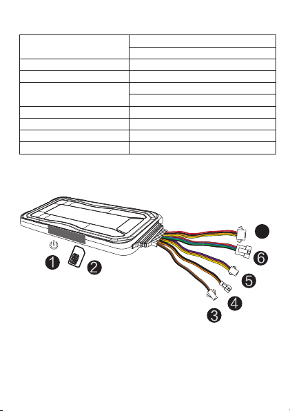
1. The standard power supply ranges from 9V to
36VDC. Please use the power wires supplied as part of
this loom. Red line means positive side while black line
means negative side.
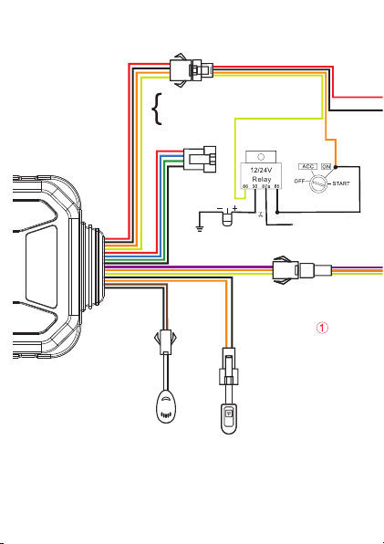
2. ACC line (orange) connects to the vehicle's ACC
switch, detecting ignition on and o.
3. Device's oil and electricity control line (yellow)
connects to relay's 86. (thin yellow line of relay socket)
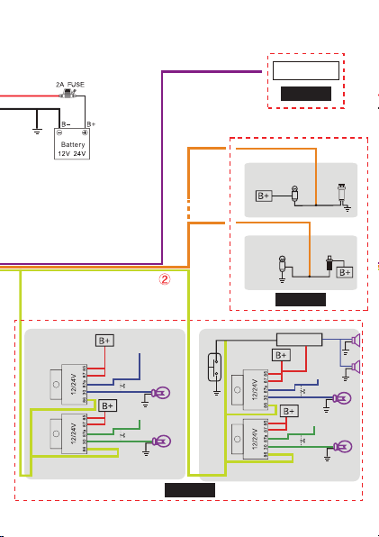
Make sure that all wiring from Power sources are
through a fusible link.
Fuel cuto relay wiring instructions
If there is an electric fuel pump in the vehicle. Locate
the Positive wire leading to the pump. The Fuel pumps
power supply can be found at the main fues box. Once
you have located the fuse. you can remove it to check
if you have found the correct power source. when the
fuse is removed the engine should stop shortly after
(this is what the relay does). Cut the positive line going
from the fuse box to the pump and wire it via the relay
as shown in the diagram 3.3 page 7. Alternatively you
can cut the ignition wiring. Again you can nd the
correct power wire by removing the fuse and testing if
the car is disabled. This kind of installation is best left
to advanced Installers or Auto electricians.
9

Note:
A12V relay is included in the kit. If the vehicle has a
24V system, then a 24V relay is needed.
4. To monitor analog signals, the purple line (ADC) of
extended features port should be connected to the
analog line.
5. To check status of car door, orange line (IN1) should
be connected between the door light and door switch
(See diagram 3).
6. To nd car remotely, please connect the yellow line
(OUT1) of extended feature port to external relays as
illustrated in diagram 3 page8.
10

11
3.5 Device Installation
Note:
There are many areas you can hide the tracker in your
vehicle. The device should face up to the sky.Metal
thermal barriers / heat shielding layers of the
windshield can aect the performance.Please keep this
in mind when looking for a suitable location
4. Operation of device
Power on/ Power off
Power on: Once you insert a valid SIM card and connect
all the wires, turn on the device by turning on the cars
ignition. The Red Power LED will ash rst. During the
signal searching process, The Green GSM LED and Blue
GPS LED will ash once. When the Blue GPS LED stays ON
Under front windsheild
underneath the dash
Inside instrument
cluster under dash
Rear windshield under
rear parcel shelf

this means the device has been located and it starts to
work. On rst turn on this may take a minute or two.
The Green LED should stop ashing within 30 seconds.
Power o: Move the power switch to the OFF position.
Reminder:
When the device is installed in a vehicle and is
connected to the vehicles power source, don’t forget
to turn on the Battery switch under the side cover.
If the battery is OFF, it can not be charged or used as
a back up in the event that the wiring is tampered
with.
5. Main Functions
5.1 SOS
In an emergency, press the SOS button for 3 seconds
to activate the SOS alarm. The device will send an SOS
SMS to the preset SOS number. The Alarm message
will also be sent to the server platform where an email
and or system message is activated. (See command
list 7-8) (Note: The Direct SMS ability is dependant on
the SIM card having SMS capability)
5.2 Power cut-off alarm
When the electricity supply of the device is cut, the
device will activate the power cut-o alarm.
12

5.3 Low battery alarm
When the internal battery is low, the device will
activate the low battery alarm.
5.4 Vibration alarm (default OFF)
When the vehicle is shaken or hit several times, the
vibration alarm is triggered.
(See command list 7-12)
5.5 Voice monitoring
Using the pre-set SOS number to dial the device, after
10 seconds, the device changes to monitoring mode.
In this mode the caller can then hear sounds inside
the vehicle.
Note:
1. A Pre-set SOS number is necessary for this function.
2. The SIM card of the calling device must have caller
ID service active
3. The SIM card Must have Voice call capability.
4. When in this mode, the device is not trackable.
5.6 Displacement alarm(default OFF)
The device will send a movement alarm when the
vehicle moves out of the pre-set distance (when ACC
is o and GPS is xed).
13

14
5.7 Oil-fuel/electrical contact CUT OFF
If the Vehicle is stolen, a fuel/electrical cut-o
command can be sent by the server platform, or via SMS.
Note:
1. Make sure the ACC is correctly connected.
2. When the ACC is OFF, the command will be
executed immediately.
3. When The ACC is ON, but the GPS does not have a
x, the command will be postponed until a GPS x is
available.
4. When The ACC is ON and the GPS has a x, the
command will be executed when the vehicle speed is
less than 20km/h.
To use this function Via SMS you have to set a "Center
number" rst. Only the "center number" can send the
cut o/restore oil/fuel command to the device. (See
command list 7-14)
Note:
1. Only the SOS number can be used to set the center
number.
2. Only the SOS number can be used to delete the
center number.
3. There is only one centre number that can be set.
4. Note the Spelling is center not re
5.8 Restore oil-fuel/electrical contact
You can send a restore command via the server
platform or via SMS and restore the vehicles power.
(See command list 7-15)

15
5.9 Restart device
If GPRS is abnormal (device is oine), you can send
SMS a command RESET# to restart the device. The
device will reboot after 20 seconds after receiving the
command.(See command list 7-16)
5.10 Door detection
This device is able to detect a door open/closed status.
(if the IN1 wire input is connected to the door switch
during installation) the tracker uploads the cars door
status to the server platform. Negative triggering is
default. When the car door's status is negative
triggering, in this case there is no need to change any
settings. If the car door status (open) is positive
triggering, the trigger polarity must be modied as
follows by sending command: DOOR,1# via SMS). See
diagram 2 (3.3) for wiring instructions. (See also
command list 7-17)
Note:
Negative triggering (default): Means when the door is
opened, the signal on the switch wire is Ground (0v);
When the door is closed, the signal level is a voltage.
Some cars/trucks with computerised interior lighting
systems may not be compatible or may require a pull
up resistor installed.

16
5.11 Analog signal
The Tracker can measure the car battery's voltage or
any other variable voltage and upload it to the server
platform. Purple wire (ADC). You can set up analog
temperature sensors, fuel sensors etc. The Voltage
range of the analog input is 0~30Vdc. See diagram
(3.3) for wiring instructions. (See command list 7-18)
5.12 Find the car by triggering
the indicators and or horn/buzzer
When Wired to do so, you can send a command that
instructs the device to ash the indicators or toot the
horn of the vehicle. See diagram 3(3.3) for wiring
instructions. (See command list 7-19)
6.Web Platform Operation
This device is factory congured to connect to the
Gator GPS tracking server platform and it is designed
to detect the network and set the APN automatically.
In most circumstances there is NO programming
required to connect to our server. However, in the
event that you wish to use the device on a third party
server please use the following guide. (manual APN
and manual server settings pg17, 6.1)
You can check to see if the device is ready to connect
to the server by observing the green LEDs status
before placing the device in its nal installed location.
the GSM LED Indicator - (Green LED) should be

17
constantly on within 30 to 40 seconds of its rst turn on.
If the LED is Solid, your ready to go to the server, set
up an account and add this device. If the indicator is
ashing you may need to check the APN settings as
the tracker may not be able to auto set this parameter.
6.1 Manual APN Setting
Web Search your Sim cards APN by searching "service
provider name_APN settings". This should lead you to
the APN name that needs to be used to allow your sim
card to connect to your providers APN (Correct APN =
Gain access to the Internet).
SMS Command APN, [apnname]#
Replace [apnname] with your service providers APN
name. (See command list 7-6)
Manual Server Setting
If you are using a third party Server (not the Gator
server). You can change the server using the following
command. Please note for 3rd party web services we
can not oer technical assistance on this topic.
SERVER,mode,domainName/IP,port,0#
E.g. SERVER,1,www.othertrackingserver.com,8011,0#
SERVER,0,211.154.135.113,8011,0#
mode = 1 means set with domain name
mode = 0 means set with IP address

18
6.2 Login Web service platform
1. Go to www.gator.net.au
2. Set up a user account
3. Add the device to your account using the IMEI
number on the Gift box (also printed on the device)
Detailed instructions are at gator.net.au (Help)
6.3 Mobile devices
Access using mobile devices is done via the web
server portal. However, on Mobile devices the portal is
optimised for mobile browsers and works more like an
App with advanced settings hidden for simplication.
For advanced settings and set up please use a lap top
or desk top computer.
7.Common Command List
Send these SMS commands in the right column to the
devices SIM card number (Phone number) to achieve
the respective functions as per list on Pages 19/20.
Do not adjust any settings that you do not understand
as this may adversely eect the devices performance

19
STATUS#
1 Device status
WHERE#
2 Device coordinate
URL#
3 Location URL
APN setting
1. Add SOS number:
SOS,A,number 1,number 2,number 3#
2.Delete subjected sequence of SOS
number:
SOS,D,number sequence 1,
number sequence 2, number sequence 3#
E.g. SOS,D,1,2,3#
3. Delete the SOS number
SOS,D,phone number#
4. Query SOS number SOS#
7
SOS setting
TIMER,T1,T2#
T1=5 18000 secon ds;ACC ON upload
interval default value10
T2=5 18000 second s ACC OFF upload
interval default value 10(when GPS is
not sleep)
9GPS data upload
time interval
1. APN, [apnname]#
E.g: APN,int ernet#
2. APN, [apnname],[user],[pwd]#
E.g: APN,internet,CLIENTE,AMENA#
SERVER,mode,domain/IP,port,0#
E.g. SERVER,1,www.ydpat.com,8011,0#
SERVER,0,211.154.135.113,8011,0#
mode1 means set with domain name
mode 0 means set with IP address
6
Server setting
VERSION#
4 Check version
GPRSSET#
5 Network setting
8
DISTANCE,D#
D=0、50 10000 meter;
Distance interval default value 300,
unit meter
10 GPS data upload
distance interval
7.Common Command List cont....
Setting SMS command

20
16
RESET#
Device restart 20 seconds after receiving
this command
Restart
DEFENSE,A#
A:1 60 minutes ,set delayed defense,
default value 10 minutes
11 Delayed defense
setting
1. SENALM,ON#
2. SENALM,OFF#
12 Vibration alarm
(default OFF)
1. MOVING,ON,R,M#
R=100 1000; Displacement radius
unit: meter
M=0-2; Alert way
0:GPRS 1:SMS+GPRS
2: GPRS+SMS+CALL
E.g. MOVING,ON,200,2#
2. MOVIN G,OFF#
13 Displacement alarm
setting
(default OFF)
RELAY,A#
A=0/1
0= restore petrol; 1=cut off petrol
Default value 0
E.g. RELAY,1#
15 Power/oil control
Set center number :
CENTER,A,mobile number#
Delete center number: CENTER,D#
14 Set centre number
DOOR,A#
A=0/1; 0 negative triggering,
1 positive triggering
default: 0
17
Car door negative/
positive triggering
setting
Upload analog data: ADT,ON,T#
T: upload interval; scope: 5 3 600(second)
Turn off analog upload:ADT,OFF#
default: OFF
18 Analog upload
setting
FIND#
19
Find car by
triggering light
and buzzer
7.Common Command List cont....
Setting SMS command
Table of contents
Other Gator GPS manuals

Gator
Gator M508 User manual

Gator
Gator GTRACK 4G Operational manual

Gator
Gator M518 User manual

Gator
Gator PT350 User manual

Gator
Gator GTRACK4G Operational manual

Gator
Gator M588T User manual

Gator
Gator iDriveZ Navi 430 User manual

Gator
Gator GTKPRO2 User manual

Gator
Gator M508 User manual

Gator
Gator GTRACK3G User manual