Gator M508 User manual

M508 GPS Tracking Device
(GPS+GPRS+GSM)
Product Manual
Edition 1.3
Copyright © 10th Oct., 2009
GATOR GROUP CO.,LTD. All rights reserved.
http://www.gatorcn.com
China Printing
ADD: 312# Ansheng Building,Xixiang section of 107 National road ,Bao'an, Shenzhen,
China
TEL: 86-75529566336
FAX: 86-75529566339
WEB: http://www.gatorcn.com

Content
1. Products Introduction...................................................................................................................4
2. Characteristics............................................................................................................................4
3. Specifications..............................................................................................................................5
3.1. Hardware Datasheet...........................................................................................................5
3.2. Other ..................................................................................................................................6
4. Interface Description.................................................................................................................7
4.1. Power Interface..................................................................................................................7
4.2. Extended Interface............................................................................................................. 8
5. Installation..................................................................................................................................9
5.1. Warm Reminder for Instalation.........................................................................................9
5.2. Wiring Diagram.................................................................................................................9
5.3. Paramete Settings...............................................................................................................9
5. Standard Accessories...............................................................................................................10
5. Optional Accessories .................................................................................................................11

Notes:
Please mount the device steadily on the flat place before using;
Please make sure the voltage value is right before connecting with battery, and
placing the wires to where shouldn’t be trodden;
Please power off when plugging or taking out of any module or connector;
Please keep the device dry and don’t let any liquid fall into the device in case any
damage caused in the device or circuit;
If any problem caused as follows, please turn to professional technician:
When power wire, keyboard, or socket are damaged;
When liquid infiltrating into the device;
When the device work unusually or cannot resume to normal even operated
according to the instruction;
When the device cannot as usual after falling, throwing or breaking;
When there is obvious damage in the device.

1. Products Introduction
GPS Tracking device mainly consists of two parts such as GPS module and GSM module.
GPS module is for getting location data from satellite, and GSM module is for transferring data to
server so that people can check the information via PC or mobile phone. Our GPS Tracking device
M528, with the best quality, stable performance and versatile functions,can be applied to various
kind of fleet management like construction trucks, rental cars, logistics vehicles and public
transportation, anti-theft system and security purpose.
2. Characteristics
1) small size, easy to install;
2) accurate GPS positioning, dynamic positioning deviation is less than 5 m;
3) support GPRS and SMS tracking mode, adopt UDP / TCP communication protocol in GPRS
mode;
4) able to get current location immediately, and support real-time tracking (GPS data uploading
at intervals);
5) support two way voice communication via handset;
6) support two way SMS communication via Mobile and PC software;
7) support authorized tapping;
8) support protection from high level voltage;
9) support the data resend from signal dead zone;
10) support remotely disable engine;
11) 3 digital inputs for detecting the status of engine, door, air condition, etc.;
12) support illegal door-open/illegal engine-start alarm, SOS alarm, power-off alarm, over-speed
alarm, parking alarm, Geo-fence alarm, fatigue driving alarm
13) support mileage statistics;
14) support remote update

3. Specifications
3.1、Hardware Datasheet
work voltage 12VDC
work current 50mA~160mA
GSM module Simcom300/340
inside contain frequency GSM 900/1800
inside contain frequency GSM 850/900/1800/1900Mhz (can
be customized)
Communication
protocol UDP/TCP(can be customized)
GPS module GPS JRC 595 with SIRFⅢchipset
GPS sensitivity -159dBm
GPS frequency L1, 1575.42 MHz
C/A coding 1.023 MHz chip rate
Channels 20 channels examine track
Position accuracy 10 meter, 2D RMS
Speed accuracy 0.1 meter/second
Time accuracy GPS time synchronization
Default data WGS-84
Recover Average 0.1 second
Hot start Average 1 second
Warm boot Average 38 second
Cold boot Average 42 second
Height limit 18,000 meter (60,000 feet) max
Speed limit 515 kilometer/second (1000 knots)max

Acceleration limit Less than 4g
3.2、Others
Work temperature -20°~70° C
Storage temperature -30°~85° C
Humidity 5% ~95% noncondensing
Terminal size 101 mm × 50mm × 24mm
Inside battery Continuous working no less than 4 hours
LED light Red: device state;yellow:GSM module state;green:GPS
module state
4. Interface Description
4.1 Power Interface

Description
pin color function explain/connection method
1 red
Power positive input, the working voltage 9VDC ~ 34VDC, connect the
positive of car battery;
2 dark Power negative input, then the negative pole of vehicle battery;
3 yellow ACC check line,connect the ACC line;
4.2 Extended interface
Description
pin color function explain/connection method
1 orange
LV1 (low-level signal detection port 1), input low voltage to detect,
voltage should be less than 0.3 VDC, connecting with effective low-level
signal wire
2 red
SOS alarm input, low-level triggered alarm, directly connect with the wire
of SOS button
3 brown
SOS alarm indicator signal, drive LED, when alarm is triggered, the LED
will be on.
4 white
HV1( high-level signal detection port 1, it is described as illegal
door-open, illegal engine-start signal detection), input positive voltage to
detect, which should be 5DC~input power supply, connecting with
effective high-level signal wire.
5 blank No description
6 purple GND of SOS alarm wire
7 yellow Relay positive input, connect with the yellow wire in relay
8 black Relay negative input, connect with the white wire in relay
9 blue
HV2( high-level signal detection port 2) input positive voltage to detect,
which should be 5DC~input power supply, connecting with effective
high-level signal wire.

5. Installation
5.1 Warm reminder for Installation
In order to realize the full functions of this product, please read this manual carefully
before starting to use the product.
1. This product can only be maintained and repaired by qualified professional service personnel. If
you detach this product for maintenance or repair, your warranty will be invalidated.
2. When connecting the other devices, read carefully their instruction manuals, so as to carry out
correct installation; do not connect incompatible device.
3. Please use genuine original parts and qualified batteries and peripheral equipments, so as to
avoid damage to this product.
4. As this product is a high-tech product, please read carefully this manual before starting to use
the product, so as to avoid inappropriate operation.
5. Drivers should not operate this product while driving a vehicle, thereby, affecting safe driving.
6. This product can work properly only when GSM communication is in good condition.
7. Please reduce electromagnetic wave interference to the product; and use it properly.
8. GPS communication is liable to be affected by environmental shielding; may fail to carry out
positioning during certain circumstances. It will resume the positioning function as soon as it
leaves the shielding environment. This is normal. Please do not worry when encountering such
problem.
9. Each signal sent out from the system will be confirmed for successful transmission in the base
station of the mobile operator. However, if system stoppage occurs or if the mobile telephone is
preset to a switch off state by the customer, it cannot ensure successful transmission.
10. For safety reason, do not tell the other people your device SIM number, without taking
precautions. Otherwise, your privacy may be compromised along with other safety problem.
5.2 Wiring diagram
5.3 Parameter settings
1. Reboot
R,* Password *
2. Settings
Format: SS,*APN*,*USERNAME*,*PASSWORD*,*IP*,*Port*,*System number*,*Phone
number for getting SMS alerts*,*Password*
e.g.:

SS,*CMNET*,**,**,*058.060.185.172*,*8886*,*13512345002*,*+8613418776340
*,*123456*
Notes:
a) If no username and password, please leave it blank,
e.g.: 1) SS, *APN*,**,**,*IP*,*Port*,*System number*,* Phone number for getting SMS
alerts *,*Password*
2) S,*APN*,*IP*,*Port*,*terminal ID*,**System number*,* Phone number for getting
SMS alerts *,*Password*
b) System number’s length must be 11 digitals, and begin with the number from 134-154;
c) Please add country code in the front of phone number, e.g.: Chinese code is 86. phone
number is 13612345678, You can set the phone number like this, *+8613612345678*
d) Default password is 123456
1. Change password
C,*password*,*new password*
6. Standard Accessories
Power Wires, GPS Antenna, GPRS Antenna, Magic Tape, Warranty Card, Warranty card receipt,
Certification

7. Optional accessories
7.1 Taping Earphone and Mic
7.2 Relay

Federal Communications Commission (FCC) Statement
This device complies with part 15 of the FCC Rules. Operation is subject to the following two
conditions: (1) This device may not cause harmful interference, and (2) this device must accept
any interference received, including interference that may cause undesired operation.
Note: This equipment has been tested and found to comply with the limits for a Class B digital
device, pursuant to part 15 of the FCC Rules. These limits are designed to provide reasonable
protection against harmful interference in a residential installation. This equipment generates, uses
and can radiate radio frequency energy and, if not installed and used in accordance with the
instructions, may cause harmful interference to radio communications. However, there is no
guarantee that interference will not occur in a particular installation. If this equipment does cause
harmful interference to radio or television reception, which can be determined by turning the
equipment off and on, the user is encouraged to try to correct the interference by one or more of
the following measures:
zReorient or relocate the receiving antenna.
zIncrease the separation between the equipment and receiver.
zConnect the equipment into an outlet on a circuit different from that to which the receiver is
connected.
zConsult the dealer or an experienced radio/TV technician for help.
Warning: Changes or modifications made to this device not expressly approved by GATOR
GROUP CO., LTD may void the FCC authorization to operate this device.
Note: The manufacturer is not responsible for any radio or tv interference caused by unauthorized
modifications to this equipment. Such modifications could void the user’s authority to operate the
equipment.
RF exposure statement:
The transmitter must not be co-located or operated in conjunction with any other antenna or transmitter.
This equipment complies with the FCC RF radiation exposure limits set forth for an uncontrolled environment.
This equipment should be installed and operated with a minimum distance of 20cm between the radiator
and any part of your body.
Other manuals for M508
1
Table of contents
Other Gator GPS manuals

Gator
Gator GTRACK4G Operational manual

Gator
Gator M588T User manual

Gator
Gator GTRACK 4G Operational manual

Gator
Gator PT350 User manual
Gator
Gator M518 User manual
Gator
Gator M508 User manual
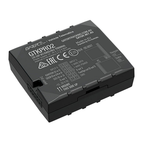
Gator
Gator GTKPRO2 User manual

Gator
Gator GTRACK3G User manual
Gator
Gator iDriveZ Navi 430 User manual
Gator
Gator GTRAKPRO User guide
